


16. Step the drive to Track 0; then, step it
back to Track 16.
17. Verify the Cats Eye pattern.
18. Step the drive to Track 26 or higher;
then, step it back to Track 16.
19. Verify the Cats Eye pattern.
20. If all the checks verify, the Radial Track
alignment is acceptable.
21. If any check does not verify, the module
must be adjusted.
RADIAL TRACK ALIGNMENT
ADJUSTMENT
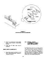
1. Loosen the three module retaining
screws 1/2-tum with a 7/64-inch Allen
wrench. Two of the screws are located un
derneath the module, and one is located
at the rear of the module (Figure 5-7).
2. Turn the cam screw counterclockwise.
3. Observe the Cats Eye pattern of the head
farthest out of alignment.
FIGURE 5-7
HEAD MODULE RETAINING AND CAM SCREW S
5-8
Summary of Contents for TM100-1
Page 8: ......
Page 11: ...FIGURE 1 1 DISK DRIVE ...
Page 12: ......
Page 18: ......
Page 29: ...WRITE PROTECT TAB WRITE PROTECT TAB FIGURE 3 5 WRITE PROTECT TAB ...
Page 34: ...FIGURE 4 4 INTERCONNECT BLOCK DIAGRAM 4 4 ...
Page 58: ...CARRIAGE ASSEMBLY FIGURE 5 14 UPPER ARM AND SCREWS ...
Page 66: ...FIGURE 6 2 LOGIC CIRCUIT BOARD MOUNTING 6 8 ...
Page 72: ...E RIN G C O N E SH A FT FIGURE 6 7 CONE S COMPONENT PARTS 6 14 ...
Page 76: ...FIGURE 6 13 INDEX EMITTER SENSOR S MOUNTING AND CABLE HARNESSING 6 18 ...
Page 79: ...FIGURE 6 16 DRIVE MOTOR HARNESSING AND MOUNTING 6 21 ...
Page 82: ...FIGURE 6 19 TRACK 0 ADJUSTMENT SCREW 6 24 ...
Page 86: ...FIGURE 6 24 UPPER ARM SCREWS 6 28 ...
Page 87: ...MOUNTING FIGURE 6 26 FELT PAD ON UPPER ARM 6 29 ...
Page 90: ......
Page 92: ...A 2 ...
Page 93: ...A 3 ...
Page 94: ......
Page 99: ...l a n d e i n CORPORATION LOGIC CIRCUIT BOARD SCHEMATIC 180011 REV F SHEET 2 OF 3 B 5 ...
Page 100: ... SV SHEET 3 OF 3 B 6 ...