


SPINDLE MOTOR CONTROL CIRCUIT
The Spindle Motor Enable signal is input via Pin
7 of the servo circuit board to gate the spindle
motor current (Figure 4-10). This current is con
trolled by an integrated regulator circuit when
the spindle motor is enabled. The potentiator
provides an adjustable D. C. voltage reference to
the regulator circuit for spindle speed adjust
ment. The tachometer signal provides feedback
from the motor via Pins 1 and 2 of the servo cir
cuit board to maintain a constant speed of 300
RPM. This signal is 12 volts A. C.
J i
4-12
Summary of Contents for TM100-1
Page 8: ......
Page 11: ...FIGURE 1 1 DISK DRIVE ...
Page 12: ......
Page 18: ......
Page 29: ...WRITE PROTECT TAB WRITE PROTECT TAB FIGURE 3 5 WRITE PROTECT TAB ...
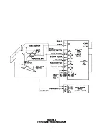
Page 34: ...FIGURE 4 4 INTERCONNECT BLOCK DIAGRAM 4 4 ...
Page 58: ...CARRIAGE ASSEMBLY FIGURE 5 14 UPPER ARM AND SCREWS ...
Page 66: ...FIGURE 6 2 LOGIC CIRCUIT BOARD MOUNTING 6 8 ...
Page 72: ...E RIN G C O N E SH A FT FIGURE 6 7 CONE S COMPONENT PARTS 6 14 ...
Page 76: ...FIGURE 6 13 INDEX EMITTER SENSOR S MOUNTING AND CABLE HARNESSING 6 18 ...
Page 79: ...FIGURE 6 16 DRIVE MOTOR HARNESSING AND MOUNTING 6 21 ...
Page 82: ...FIGURE 6 19 TRACK 0 ADJUSTMENT SCREW 6 24 ...
Page 86: ...FIGURE 6 24 UPPER ARM SCREWS 6 28 ...
Page 87: ...MOUNTING FIGURE 6 26 FELT PAD ON UPPER ARM 6 29 ...
Page 90: ......
Page 92: ...A 2 ...
Page 93: ...A 3 ...
Page 94: ......
Page 99: ...l a n d e i n CORPORATION LOGIC CIRCUIT BOARD SCHEMATIC 180011 REV F SHEET 2 OF 3 B 5 ...
Page 100: ... SV SHEET 3 OF 3 B 6 ...