Assembly and Installation Instructions
for the AudioScience Microphone
D50053, Revision 5.0
Page 7
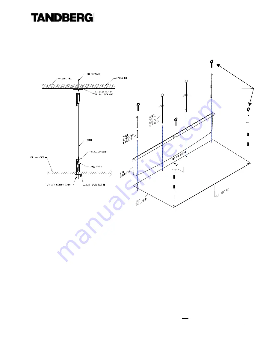
8. With the assistance of another person, attach the AudioScience microphone assembly to the
ceiling. This is done by supporting the plastic boundary structure while the cable suspension
assemblies are threaded onto the ceiling clips. If the Eye-bolts were used instead, then simply
tie the hangings to the eye-bolts.
9. Attach the two safety cables to the AudioScience microphone, and connect them to solid
anchoring points in the ceiling.
Do Not
attach the safety cables to electrical or other wiring.
(The
¼
” universal snap hooks and the bailing wire may be used to achieve this.) Allow
enough slack to let the ceiling tiles slide into place, but not enough to allow the microphone
unit to hit anyone in the case of ceiling track failure.
10. Push back the ceiling tiles located directly above the microphone unit. Route the microphone
cable up from the hole in the top deflector, along one of the safety cables, to the ceiling. Use
the supplied cable ties to attach the microphone cable to the safety cable.
11. Plug the 47’ microphone cable assembly into the XLR connector connected to the microphone
capsule. Route the cable across the ceiling and down a wall located near the
Videoconferencing system. If the cable is to be installed in a wall, a “fish tape” or conduit
may be necessary to get the cable from the ceiling to the floor.
12. Within the black XLR connector attached to the microphone capsule is a switch which is
accessible from the side of the XLR connector. Switch it to the “ ” position.
Optional
Eye-Bolts


