background image


Assembly and Installation Instructions 
for the AudioScience Microphone 
D50053, Revision 5.0 

Page 4


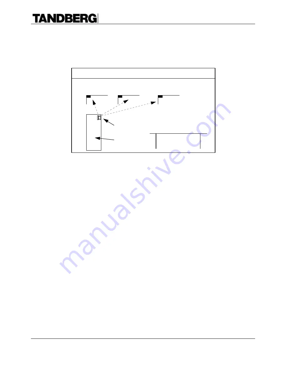
4.  The microphone should be mounted far enough away from the videoconferencing system such 

that one or both boundaries of the microphone are between the microphone element and the 
loudspeakers of the videoconferencing system to prevent coupling of the direct sound from 
the speakers into the microphone element. 


Bad

Good

Best

Table

Loudspeaker

Videoconferencing
System

Selecting a mounting location:

Minimum Distance from Videoconferencing system


5.  The mounting holes of the microphone boundary must be directly under a ceiling track to 

allow for mounting hardware. Additionally, to allow for easier changing of lighting tubes or 
bulbs, the microphone should not be mounted where the microphone blocks these items.  If, 
due to acoustic concerns, a light fixture has to be “blocked” then string the microphone cable 
in such a way as to allow for removal of the microphone when light bulbs or tubes need to be 
changed. 

 
6.  If more than one microphone is to be used, consult your TANDBERG Dealer for 

recommendations on mounting locations of the AudioScience microphone.  TANDBERG has 
available a document 

The TANDBERG AudioScience Microphone: Theory and Operation

which can be helpful in understanding the issues involved with operating in a multiple 
microphone environment. 


Summary of Contents for AudioScience D 50053

Page 1: ...Assembly and Installation Instructions for the AudioScience Microphone TANDBERG D 50053 Rev 5 0...

Page 2: ...Microphone Assembly 1 Rear Deflector 4 Cable Suspension Assemblies 2 Safety Cable Assemblies 4 9 16 Ceiling Track Clips 4 15 16 Ceiling Track Clips 4 20 x 1 Eye Bolts 2 1 4 Universal Snap Hooks 1 47...

Page 3: ...rophone is 47 feet 14 4 meters long and plenum rated to comply with fire code regulations This allows the microphone to be mounted up to about 30 ceiling feet 9 2 meters away from the system If the mi...

Page 4: ...ing positions should be within 14 horizontal feet 4 3 meters of the microphone capsule with an unobstructed line of sight to the microphone capsule 2 The supplied hardware is for mounting the micropho...

Page 5: ...phone boundary must be directly under a ceiling track to allow for mounting hardware Additionally to allow for easier changing of lighting tubes or bulbs the microphone should not be mounted where the...

Page 6: ...s for the AudioScience Microphone D50053 Revision 5 0 Page 5 Typical Room Mounting Arrangement 14 4 3m Maximum M I C 14 4 3m Maximum M I C M I C Typical Boardroom Mounting Arrangement 14 4 3m Maximum...

Page 7: ...eiling track clips have been included Four are for 9 16 ceiling tracks and four are for 15 16 24 mm ceiling tracks Discard the four that are not required 5 Attach the ceiling clips to the ceiling grid...

Page 8: ...e ceiling tiles slide into place but not enough to allow the microphone unit to hit anyone in the case of ceiling track failure 10 Push back the ceiling tiles located directly above the microphone uni...

Page 9: ...13 Replace the ceiling tiles Small notches may need to be cut in the ceiling tiles to allow for the microphone cable and safety cables 14 Using the Brillianize plastic cleaner and the Sofkloth towel w...

Page 10: ...enser Impedance 240 Ohms Open Circuit Sensitivity 7mV Pa 43dB re 1V Pa Power Sensitivity 43dB re 1mW Pa Equivalent Noise Level 20dB SPL typical 0dB 0002 dyne cm2 A weighted S N ratio 74dB minimum at 9...

Page 11: ...Assembly and Installation Instructions for the AudioScience Microphone D50053 Revision 5 0 Page 10 Acoustical Frequency response Horizontal Polar response...

Reviews: