background image

5

32

33

34


35

36

37


38

39

40


000Book̲TCG40EAS̲WE.indb   5

000Book̲TCG40EAS̲WE.indb   5

2011/01/13   10:04:28

2011/01/13   10:04:28

Summary of Contents for TCG 40EAS

Page 1: ...er la machine Antes de utilizar esta m quina lea cuidadosamente el manual Leia o manual atentamente antes de operar esta m quina Handling instructions Mode d emploi Instrucciones de manejo Instru es d...

Page 2: ...2 1 2 3 4 5 6 7 8 9 10 1 2 3 8 7 5 6 4 9 000Book TCG40EAS WE indb 2 000Book TCG40EAS WE indb 2 2011 01 13 10 04 22 2011 01 13 10 04 22...

Page 3: ...3 11 12 13 14 15 16 17 18 19 16 17 10 11 12 15 14 13 25 50 A B 1 000Book TCG40EAS WE indb 3 000Book TCG40EAS WE indb 3 2011 01 13 10 04 25 2011 01 13 10 04 25...

Page 4: ...4 20 21 22 23 24 25 26 27 28 29 30 31 18 19 20 23 19 21 22 18 a b T 24 13 15m 0 6mm 000Book TCG40EAS WE indb 4 000Book TCG40EAS WE indb 4 2011 01 13 10 04 26 2011 01 13 10 04 26...

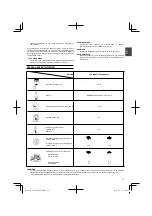
Page 5: ...5 32 33 34 35 36 37 38 39 40 000Book TCG40EAS WE indb 5 000Book TCG40EAS WE indb 5 2011 01 13 10 04 28 2011 01 13 10 04 28...

Page 6: ...g this unit Use anti slip and sturdy footwear Keep all children bystanders and helpers 15 m away from the unit If anyone approaches you stop the engine and cutting attachment immediately Blade thrust...

Page 7: ...your unit 1 Fuel cap 2 Throttle lever 3 Starter handle 4 Blade guard 5 Cutting attachment 6 Drive shaft tube 7 Handle 8 Suspension eyelet 9 Ignition switch 10 Harness 11 Clutch case 12 Choke lever 13...

Page 8: ...witches furnaces etc WARNING Fuel is easy to ignite or get explosion or inhale fumes so that pay special attention when handling or filling fuel Cutting safety Do not cut any material other than grass...

Page 9: ...5 110 Vibration level m s2 ISO7916 Front handle Rear handle Left handle Right handle 3 4 3 4 5 5 5 3 NOTE Equivalent noise level vibration level are calculated as the time weighted energy total for no...

Page 10: ...re facing the correct direction Align the notch hole of the cutter holder with the hole on the gear case Top the gear case and insert the Allen wrench to stop turning Turn the fixing nut clockwise and...

Page 11: ...firmly by one hand and then remove the hook 19 of the shoulder harness from the hanger 20 Fig 23 a How to reinstall the hook after using the emergency release pinch It needs to go through the buckle...

Page 12: ...y in the TCG 40EAS P Cylinder Engine cooling Fig 32 The engine is air cooled and air must circulate freely around engine and over cooling fins on cylinder head to prevent overheating Every 100 operati...

Page 13: ...specially the cord and return spring Clean the exterior of the spark plug Remove it and check the electrode gap Adjust it to 0 6 mm or change the spark plug Clean the cooling fins on the cylinder and...

Page 14: ...14 E 15 15 16 17 18 18 20 000Book TCG40EAS WE indb 14 000Book TCG40EAS WE indb 14 2011 01 13 10 04 34 2011 01 13 10 04 34...

Page 15: ...15 10 5 14 6 9 2 11 8 13 7 12 3 1 15 16 4 K 1 2 3 4 5 6 7 8 9 10 11 12 13 14 15 16 G B G R F R E S P T 000Book TCG40EAS WE indb 15 000Book TCG40EAS WE indb 15 2011 01 13 10 04 34 2011 01 13 10 04 34...

Page 16: ...16 HAVS 3 15 Tanaka 000Book TCG40EAS WE indb 16 000Book TCG40EAS WE indb 16 2011 01 13 10 04 35 2011 01 13 10 04 35...

Page 17: ...BPMR6A l 1 00 kg 7 5 LpA dB A EN27917 90 LwA dB A LwA dB A 108 8 110 105 110 m s2 ISO7916 3 4 3 4 5 5 5 3 1 2 1 2 Tanaka G B G R F R E S P T 000Book TCG40EAS WE indb 17 000Book TCG40EAS WE indb 17 20...

Page 18: ...18 1 1 1 2 2 3 3 4 5 4 5 6 7 8 5 4 6 7 8 9 10 11 Allen Allen 13 11 11 Allen 11 10 Allen 11 12 15 000Book TCG40EAS WE indb 18 000Book TCG40EAS WE indb 18 2011 01 13 10 04 37 2011 01 13 10 04 37...

Page 19: ...W 30 3 16 1 13 RUN 16 16 17 2 14 15 3 CLOSED 17 18 4 19 5 RUN 2 5 6 2 3 20 21 22 6500 15 23 21 21 19 20 23 a 21 19 22 23 22 23 b 19 19 20 23 a 18 23 a G B G R F R E S P T 000Book TCG40EAS WE indb 19...

Page 20: ...20 24 13 6500 16 25 26 11 14 H H E 27 T T Tanaka 2500 3000 28 24 29 30 0 6 100 31 100 TCG 40EAS P 000Book TCG40EAS WE indb 20 000Book TCG40EAS WE indb 20 2011 01 13 10 04 37 2011 01 13 10 04 37...

Page 21: ...21 32 100 33 50 3 4 34 Tanaka 25 4 3 35 36 37 10 38 15 16 40 2 5 Tanaka 0 6 3 4 G B G R F R E S P T 000Book TCG40EAS WE indb 21 000Book TCG40EAS WE indb 21 2011 01 13 10 04 38 2011 01 13 10 04 38...

Page 22: ...tion ainsi qu un casque et des protections d oreilles lorsque vous utilisez ce produit Utilisez des chaussures antid rapantes et solides Maintenez les enfants spectateurs et aides plus de 15 m de l ap...

Page 23: ...du r servoir de carburant 2 Commande des gaz 3 Poign e du lanceur 4 Prot ge lame 5 Outil de coupe 6 Tube de transmission 7 Poign e 8 illet d accrochage 9 Interrupteur marche arr t 10 Harnais 11 Carter...

Page 24: ...d huile Vidangez le r servoir de carburant avant de ranger la machine Cette op ration est recommand e apr s chaque utilisation Si le r servoir n est pas vide rangez alors la machine dans une position...

Page 25: ...e 1 2 ralenti 1 2 vitesse de course Toutes les donn es sont susceptibles d tre modifi es sans pr avis Dans l ventualit de situations qui ne seraient pas prises en compte par le pr sent manuel redouble...

Page 26: ...re enlev du prot ge lame Pour enlever l extension de protection r f rez vous aux illustrations Portez des gants l extension poss dant un limiteur aiguis puis apr s avoir retir la vis poussez les deux...

Page 27: ...roussaillage L utilisation prolong e de la machine au ralenti peut aboutir une usure pr matur e de l embrayage Coupez l herbe de la droite vers la gauche Une r action de pouss e de la lame peut surven...

Page 28: ...moteur tourne au ralenti Filtre air Fig 28 Nettoyez le filtre air r guli rement pour viter les troubles de fonctionnement du carburateur les probl mes de d marrage les pertes de puissance l usure pr...

Page 29: ...ez ensuite le fil nylon par le trou sur le c t de la t te fil nylon et repositionnez le cache de l ensemble de coupe dans le sens inverse du d montage Tirez les fils nylon gauche et droit jusqu ce qu...

Page 30: ...lizante y resistente Haga que los ni os sus ayudantes o cualquier otra persona se mantengan a una distancia de 15 m del aparato Si alguien se acerca a usted detenga el motor y el mecanismo de corte de...

Page 31: ...del arrancador 4 Protector de la cuchilla 5 Mecanismo de corte 6 Eje de transmisi n 7 Asidero 8 Ojal de la suspensi n 9 Llave de ignici n 10 Arn s 11 Carcasa del embrague 12 Palanca del est rter 13 Mo...

Page 32: ...dar el aparato Se recomienda vaciar el dep sito de combustible cada vez que termine de utilizar el aparato Si deja combustible en el dep sito aseg rese de que no van a producirse escapes Guarde el apa...

Page 33: ...datos est n sujetos a cambios sin previo aviso Si se producen situaciones no previstas en este manual utilice el sentido com n P ngase en contacto con su distribuidor de Tanaka si necesita ayuda Dediq...

Page 34: ...extensi n del protector siga los diagramas Utilice guantes siempre que la extensi n est equipada con un limitador de l nea afilado A continuaci n presione las dos pesta as cuadradas del protector una...

Page 35: ...ue el motor se caliente durante 2 3 minutos antes de someterlo a ninguna presi n Corte Fig 20 21 22 Cuando corte haga funcionar el motor a m s de 6500 rpm La utilizaci n prolongada a pocas rpm podr a...

Page 36: ...s el motor est al ralent el mecanismo de corte no deber a girar en ning n caso Filtro de aire Fig 28 Limpie el polvo y la suciedad del filtro de aire para evitar Fallos de funcionamiento del carburado...

Page 37: ...mente a la apertura de la bobina a unos 10 cm del extremo Fig 38 A continuaci n pase la l nea de nylon por el agujero lateral del cabezal de nylon y coloque la tapa del cuerpo de corte al contrario de...

Page 38: ...s durante a utiliza o do aparelho Utilize cal ado robusto e n o deslizante Mantenha todas as crian as pessoas e ajudantes a 15 metros de dist ncia da unidade Se algu m se aproximar de si pare imediata...

Page 39: ...dor 3 Punho de arranque 4 Protec o da l mina 5 Acess rio de corte 6 Tubo do veio de transmiss o 7 Pega 8 Olhal de suspens o 9 Interruptor de igni o 10 Gancho 11 Caixa de embraiagem 12 Alavanca do ar 1...

Page 40: ...o aparelho num local onde os vapores do combust vel n o possam entrar em contacto com fa scas ou chamas abertas de aquecedores de gua motores ou interruptores el ctricos fornos etc ADVERT NCIA O comb...

Page 41: ...valentes foram calculados como a energia total do tempo ponderado para os n veis de ru do vibra o em diferentes condi es de trabalho com a seguinte distribui o do tempo 1 2 ao ralenti 1 2 em acelera o...

Page 42: ...vez que a extens o tem um limitador de linhas afiado de seguida prima as duas patilhas uma por uma ap s ter retirado o parafuso Fig 10 Instala o da l mina de corte Fig 11 Quando instalar uma l mina d...

Page 43: ...uer carga Cortar Fig 20 21 22 Quando cortar accione o motor acima de 6500 rpm Uma utiliza o prolongada a baixas rota es poder desgastar prematuramente a embraiagem Corte a relva da direita para a esqu...

Page 44: ...filtro de ar e o filtro 24 Lave os em gua de sab o morna Verifique se o filtro est seco antes de mont lo novamente Um filtro de ar em uso que tenha sido usado por algum tempo nunca poder ficar totalme...

Page 45: ...tarem fixas a cerca de 15 16 cm do fim Fig 40 NOTA A cabe a de nylon est concebida para linhas de nylon com um di metro exterior de 2 5 mm N o utilize linhas de nylon com um di metro exterior diferent...

Page 46: ...53 7 1 53 7 8 53 7 3 53 7 2 53 7 4 53 7 7 53 7 5 53 7 6 54 56B 56A 56 57 57A 57B 53 7 53 55 22 20B 20A 20 18 2 18 18 1 25 23 26 24 21 27 8 27 7 27 6 27 9 27 1 29 29A 27 5 27 4 27 11 27 10 27 10A 27 10...

Page 47: ...Head Cap Screw M6 70 2 35 Hex socket Head Cap Screw M5 12 1 35A Spring washer 1 35B Plain washer 1 36 Hex socket Head Cap Screw M5 16 2 36A Spring washer 2 36B Plain washer 2 37 Mu er cover 1 39 Gask...

Page 48: ...3 27 11A 27 2 27A 21 7 7A 53 6 53 5 53 3 1 11 14 13 15 16 52 50 39 40 41B 41A 41 42 43 44 44 3 44 1 45 46 47 48 49 49 2 49 1 6 5 4 2 60 61 58 59B 59A 59 44 2 53 2 53 4 53 1 57B 57A 57 56 56A 56B 54 5...

Page 49: ...lain washer 2 34 Hex socket Head Cap Screw M6 70 2 35 Hex socket Head Cap Screw M5 12 1 35A Spring washer 1 35B Plain washer 1 36 Hex socket Head Cap Screw M5 16 2 36A Spring washer 2 36B Plain washer...

Page 50: ...50 000Book TCG40EAS WE indb 50 000Book TCG40EAS WE indb 50 2011 01 13 10 04 51 2011 01 13 10 04 51...

Page 51: ...Harness Ass y 1 36 Lever Ass y 1 37 Screw ST2 9 13 1 38 Button 1 39 Spring 1 40 Clock Pin 1 41 Throttle Lever 1 42 Spring 1 43 Box Right 1 44 Screw ST2 9 18 3 45 Screw M5 30 1 46 Cable Comp 1 47 Tube...

Page 52: ...ramos para os devidos efeitos que este produto cumpre os requisitos das directivas comunit rias 2006 42 CE 2004 108 CE e 2000 14 CE As seguintes normas harmonizadas foram aplicadas ISO 7112 7113 7916...

Reviews: