34
4
.
2
.
4
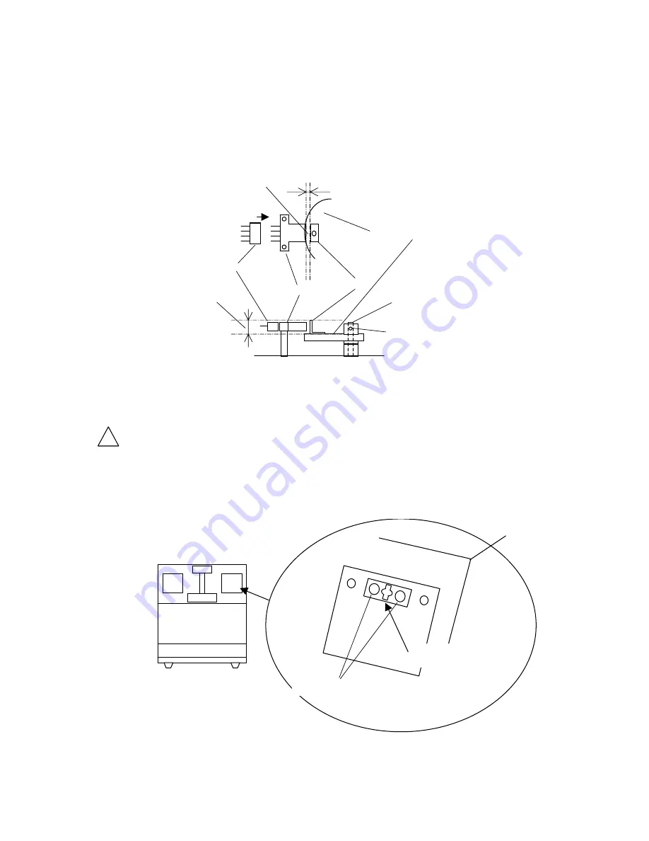
Photo Micro Sensor
(1) Remove the arm cover.
(2) Pull out the sensor socket from the photo sensor.
(3) Remove the photo sensor from the arm.
(4) Attach new photo sensor in reverse order.
2 ~ 4 mm
The reflector does not touch the photo sensor
Reflector
Photo Micro Sensor
Socket
Cam for Application
The reflector covers
the photo micro sensor
Motor Shaft
Height Adjuster
Fig. 27 Position of Photo Micro Sensor
4
.
2
.
5
Electric Igniter
Caution: Adjust filament output when a new igniter is installed. See 2.1
on page 9 to 10.
Insert a thin Phillips driver to the center hole of the igniter terminal. Hold the connector of
the igniter, then pull out it with pushing driver. See
Fig. 28
.
Terminal for Igniter
Push here when pulling wires
Fig. 28 Electric Igniter Terminal
!


