—
TABLE OF CONTENTS
—
• Optical Axis Fine Adjustment Using the Sound Check ..... 10
• Optical Axis Fine Adjustment Using the Monitor
Output Voltage................................................................... 11
• Optical Axis Fine Adjustment Using the Alignment
Wireless Checker (Sold Separately).................................. 11
7 OPERATION CHECK .................................................................. 12
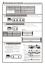
8 EXPLANATION OF FUNCTIONS
8-1 MODULATION FREQUENCY CHANGEOVER FUNCTION ........ 13
8-2 TRANSMISSION POWER SELECTION FUNCTION.......... 13
8-3 ALARM MEMORY DISPLAY FUNCTION ........................... 13
8-4 SOUND CHECK FUNCTION .............................................. 14
8-5 RESPONSE TIME ADJUSTMENT FUNCTION .................. 14
8-6 UPPER/LOWER CHANGEOVER FUNCTION.................... 14
8-7 AUTO GAIN LOCK FUNCTION .......................................... 14
8-8 TRANSMITTER LED SWITCH............................................ 15
8-9 LIGHT SENSITIVITY SIGNAL FUNCTION ......................... 15
8-10 PROGRAMMABLE AGC FUNCTION ................................. 15
8-11 EXTERNAL ENVIRONMENT DIAGNOSTIC FUNCTION ....... 15
8-12 ALIGNMENT WIRELESS CHECKER CONNECTION
FUNCTION .......................................................................... 15
9 TROUBLESHOOTING ................................................................ 15
10 SPECIFICATIONS....................................................................... 16
11 EXTERNAL DIMENSIONS Unit: inch (mm) ................................ 16
1 PRODUCT COMPONENTS
1-1 PARTS
DESCRIPTION ......................................................... 2
1-2 ACCESSORIES..................................................................... 2
1-3 NAMES OF OPERATION SECTION..................................... 3
2 OPERATING PRECAUTIONS
2-1 EXAMPLE OF INCORRECT INSTALLATION....................... 3
3 PRECAUTIONS
3-1 PROTECTION DISTANCE AND RANGE OF LIGHT
BEAM
COVERAGE ............................................................... 4
3-2 MOUNTING
HEIGHT ............................................................ 4
3-3 OPTICAL AXIS ADJUSTMENT RANGE ............................... 5
3-4 EXAMPLE OF PRACTICAL APPLICATION.......................... 5
4 INSTALLATION METHOD
4-1 INSTALLATION INTO HOUSING.......................................... 6
5 WIRING METHOD
5-1 POSITION AND RATING OF TERMINALS........................... 6
5-2 WIRING DISTANCE BETWEEN SENSOR AND
POWER
SUPPLY.................................................................. 6
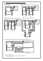
5-3 WIRING DISTRIBUTION DIAGRAM (WIRING DIAGRAM) .. 7
6 OPTICAL AXIS ADJUSTMENT
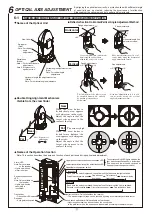
6-1 NAMES AND FUNCTIONS OF OPTICAL AXIS
ADJUSTMENT
PARTS ......................................................... 8
6-2 OPTICAL AXIS ADJUSTMENT USING
THE ALIGNMENT MECHANISM .......................................... 9
Check that the following transmitter, receiver, and accessories are included in the box when you first
unpack the product.
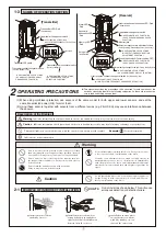
1-1
PARTS DESCRIPTION
1-2
Accessories
1
PRODUCT COMPONENTS
This section describes the contents of the product package and the names and functions of
the parts that appear in this instruction manual.
Instruction Manual
(This Manual)
: 1 pc
Panhead screw
(M3×12mm)
: 8 pcs
View finder
Reflector
Horizontal angle fine
adjustment screw (White)
Vertical angle
adjustment screw (Red)
Wiring terminal
Wiring terminal
Swivel base (White)
(Horizontal angle
adjustment)
Sensor body : 2 pcs (Transmitter: 1 pc, Receiver: 1 pc)
Swing arm (Red)
(Vertical angle adjustment)
Upper optical unit
Lower optical unit
TRANSMITTER
RECEIVER
Fluorescent yellow
Fluorescent orange
1-3
NAME OF OPERATION
SETTING
Auto gain lock switch
Transmitter LED switch


