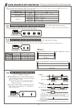
Sensitivity
attenuation LED
Note: Only installed on the receiver
8-9
: Lit
Note: Installed on the transmitter and the receiver
8-12
Note: Only installed on the receiver
8-10
Note: Only installed on the receiver
8-11
Beep
(high pitch beep)
(1 sec)
Beep-beep-beep
(high pitch beep)
(Intermittent sound
for 20 seconds)
Beep sound
Result
Auto gain lock pass/fail criteria
Pass
Fail
Cause
Remedy
Light reception
authorization LED
Off for both
upper and lower
(2) Light reception level is low
due to misalignment of the
optical axis.
Note: The sensitivity
attenuation LED is also lit
(1) Light was being obstructed
when the receiver cover
was attached.
(2) Also, remove the cover from the
transmitter, check the actual
protection distance and
transmission power before
adjusting the optical axis again.
(1) Remove the item that is
obstructing the light beams,
re-attach the receiver cover, and
check the beep sound.
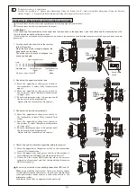
TROUBLESHOOTING
Daily Inspections
9
(1) Power is not on
(2) Poor wiring or breaking of wire, short
(3) Transmitter is set to [Do not transmit]
(1) Connect the power source
(2) Check again
(3) Press the upper/lower changeover switch
(1) Connect the power source
(2) Check again
(3) Remove the reflecting object, or change the
installation location or optical axis direction
(4) Obstruct four levels simultaneously
(5) Shorten the detection response time
(1) Power is not on
(2) Poor wiring or breaking of wire, short
(3) Photoelectric beam is reflected by some object and entering the receiver
(4) Four levels are not obstructed simultaneously
(5) Sensor beam is obstructed for less time than the detection response
time setting in the receiver
(1) Optical axis (alignment) is not aligned correctly
(2) There is an obstruction between the transmitter and receiver
(3) Transmitter/receiver cover or reflection section is dirty
(4) Frequency channel settings on the transmitter and receiver do not match
(1) Poor wiring connection
(2) Change of supply voltage
(3) Obstruction between transmitter and receiver (objects such as branches
that move with the wind)
(4) The wiring of the transmitter/receiver is located nearby a power line
(5) Unstable sensor installation
(6) Transmitter/receiver cover or reflection section is dirty
(7) Improper alignment of optical axis
(8) A large bird or cat may obstruct the beams
(9) Transmission power switch is set to L, which does not keep enough
margin of sensitivity
(1) Check again
(2) Stabilize the supply voltage
(3) Remove the object
(4) Change the wiring route
(5) Fix in a stable location
(6) Clean using a soft cloth
(7) Perform optical axis adjustment again, set the gain lock
and secure the margin of sensitivity
(8) Set the response time to be slightly longer (however, this
is not possible if there is a possibility that an intruder
could run through at top speed)
(9) Set the transmission power switch to H, remove the
receiver cover and set the gain lock again
(1) Perform angle adjustment again and set the gain lock
(2) Remove the object
(3) Clean using a soft cloth
(4) Readjust the frequency channels so they are the same
Transmitter LED does not light
(cover is open)
Alarm LED does not go out
(Alarm output does not stop)
Continually activated
Status
Cause
Remedy
Alarm LED does not light even if
the photoelectric beam is obstructed
• Check the device by referring to the table below. If you cannot restore the device to a normal
condition after the check, contact the place of purchase or TAKEX.
To clean the device, use a soft, wet cloth and then wipe off any water drops.
If the device is particularly dirty, dip the soft cloth in water that includes a weak neutral detergent. Wipe the device gently with the cloth, then
wipe off any detergent that remains. Do not use substances such as thinner or benzene. (The plastic parts may deform, discolor or change
their properties.)
Perform operation checks on a regular weekly basis.
PROGRAMMABLE AGC FUNCTION
LIGHT SENSITIVITY SIGNAL FUNCTION
EXTERNAL ENVIRONMENT DIAGNOSTIC FUNCTION
ALIGNMENT WIRELESS CHECKER CONNECTION FUNCTION
: Off
: Lit
: Flashing
When the receiver cover is attached, the
display appears and the beep sound is
generated in approximately 5 seconds
according to the pass/fail result.
For detailed information, refer to the
table on the right.
Note: The beep sound is generated
regardless of the setting of the
sound check switch.
Light reception level for
both the upper and lower
beams is insufficient
Light reception level
for the upper beam is
insufficient
Light reception level
for the lower beam is
insufficient
During adverse environmental conditions such as dense fog or heavy rain, this function temporarily increases the sensitivity of the
receiver.
Note: The margin of sensitivity is maintained even if there is a sudden worsening in weather conditions.
The LED lights up when the light reception level is considered to be insufficient
in order to notify the operator of that an inspection is necessary.
The light reception level falls below the specified level under adverse environmental conditions such as dense fog or heavy rain. This function issues
an environmental output if such conditions are maintained.
Note: The environmental output continues until the light reception level for both the upper and lower beams recovers to the specified level (for 5
seconds at the shortest).
Using the alignment wireless checker that is sold separately enables easy and accurate optical axis adjustment.
Providing sufficient margin of sensitivity increases the resistance to the dense fog, snow, and heavy rain, which makes it possible to construct a
highly reliable intrusion alert system.
8-8
TRANSMITTER LED SWITCH
The transmitter LED can be turned off.

