Calibration
172
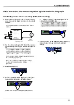
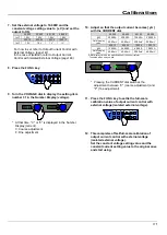
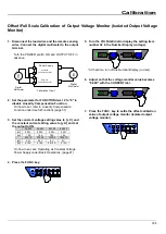
Output Voltage Control with External Resistance(C)
1. Disconnect the load wires and the remote
sensing wires. Connect the digital multimeter to
the output terminal.
Turn the POWER switch ON and OUTPUT OFF in
advance.
Power Supply
+
-
V
+
-
Digital
Multimeter
Calibration Circuit
4
17
External
Control Connector
External Resistance
0 to 10k
Ω
2. Set the external resistance to 10kΩ and the
constant current setting value to [ yA ] and set
the output to ON.
30-200
30-400
60-100
60-200
[yA]
1.0A
1.0A
1.0A
1.0A
500-12
500-24
1000-6
1000-12
[yA]
0.10A
0.10A
0.010A
0.10A
On how to set, refer to Output Voltage Control with
External Resistance (C).(page140)
3. Press the FUNC. key.
4. Turn the VOLTAGE dial to display the setting item
number 28 in the Number Display (voltage).
* At that time, turn off the Number Display (current).
5. Adjust so that the output voltage becomes
"0.000V" with the CURRENT dial.
6. Press the FUNC. key to settle the offset calibration
value of output voltage control with external
resistance (C).
Summary of Contents for HX-S-G4 Series
Page 157: ...Special Loads 157 This page is blank...
Page 161: ...Maintenance 161 This page is blank...
Page 197: ...Specifications 197 External Diagrams 1 HX S 030 200G4 F I...
Page 198: ...Specifications 198 2 HX S 030 400G4 F I...
Page 199: ...Specifications 199 3 HX S 060 100G4 F I...
Page 200: ...Specifications 200 4 HX S 060 200G4 F I...
Page 201: ...Specifications 201 5 HX S 0500 12G4 F I...
Page 202: ...Specifications 202 6 HX S 0500 24G4 F I...
Page 203: ...Specifications 203 7 HX S 01000 6G4 F I...


