background image

TagMaster AB 


HW Installation Guide 

INTRODUCTION 

Manual issue 01 


7

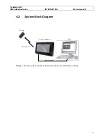
4.2 System 

Block 

Diagram 


Microwaves 

S1566 HD Reader 

Interface cable 

ID-Tag 

Host  


Diagram to show system and interconnections with a host and relation with tag. 

Summary of Contents for S1566

Page 1: ...TagMaster AB TagMaster AB TagMaster S1566 Heavy Duty HW Installation Guide Manual issue 01 ...

Page 2: ...ired operation NOTE This equipment has been tested and found to comply with the limits for a Class A digital device pursuant to part 15 of the FCC Rules These limits are designed to provide reasonable protection against harmful interference when the equipment is operated in a commercial environment This equipment generates uses and can radiate radio frequency energy and if not installed and used i...

Page 3: ...IRONMENTAL CONSIDERATIONS 12 7 1 General 12 7 2 Electromagnetic immunity 12 8 ELECTRICAL REQUIREMENTS 13 8 1 Temperature 13 8 1 1 Communicators 13 8 1 2 Tags 13 8 2 Supply Voltage 13 8 3 Radio Interface 13 9 MECHANICAL INSTALLATION 15 9 1 General 15 9 2 Readers 15 9 2 1 Mounting 15 9 2 2 Connecting Cable recommendation 16 9 3 ID Tags 17 10 ELECTRICAL CONNECTIONS 18 11 EARTHING REQUIREMENTS 19 12 S...

Page 4: ...ONTENTS Manual issue 01 4 13 3 Interference 22 13 4 Using wrong address 22 13 5 Forgetting the free wheel diode across inductive loads 22 13 6 Using different data speed in the Tag s and in the Reader s 22 13 7 Using an unsuitable power supply 23 ...

Page 5: ...umbering standard to identify the document version This standard uses the form P01A P01B to P01n for draft versions not for customer issue then 01 for a released version reviewed can be given to the customer Subsequent issues use 02 03 04 etc and are changed via the formal change control process 3 ASSOCIATED DOCUMENTATION 51027803 TagMaster AB TagMaster HW Installation Guide 51021106 TagMaster AB ...

Page 6: ...HD Reader 4 1 Audience The intended audience for this document is system integrators installation engineers contractors or the like who have the task to install and commission the TagMaster systems The audience is expected to have adequate experience and education in the field of installation and commissioning of control and identification systems and to be qualified for electrical installations ...

Page 7: ...B HW Installation Guide INTRODUCTION Manual issue 01 7 4 2 System Block Diagram Microwaves S1566 HD Reader Interface cable ID Tag Host Diagram to show system and interconnections with a host and relation with tag ...

Page 8: ...sheet for further details Solid Solid is the S1501 and S1566 standard software delivered from factory This software receives ConfiTalk commands on the serial port and executes them This is the same as the ConfiTalk only mode of the S1500 Tag ID carrier e g ScriptTag S1251 in the CONFIDENT system which is read writable via microwaves using a Communicator 4 4 References Communicator S1500 S1501 data...

Page 9: ...r representative should be notified in order to facilitate repair or replacement of the equipment The equipment described in this manual is designed to be used by properly trained personnel only Installation adjustments and maintenance of the exposed equipment shall be carried out by qualified personnel who are aware of the hazards involved and who are qualified for electrical installations For co...

Page 10: ...ground can make the equipment dangerous if it is connected to a defective power supply The power supply used to provide the equipment with 24 or 12 VDC must comply with all relevant safety regulations It must also be made for connection to the local mains voltage and be able to provide the necessary power without producing excessive heat Fuses shall only be renewed by a qualified person who is awa...

Page 11: ...2 interface 6 2 ID Tags An ID Tag is a device carrying ID information that can be read at a long distance using microwaves Versions that can be read at a distance of up to 8 meters with the Reader S1503 are available The actual reading range depend on the Reader type Also different shaped versions of the tags are available Some have the shape of a credit card but is slightly thicker Each Tag has i...

Page 12: ...ironments Electromagnetic interference on the microwave link Industrial noise is typically present in the KHz and low MHz frequency band The TagMaster system is only receptive for frequencies closed to 2 45 GHz so typical industrial noise will not affect the microwave communication Transients from spot welding equipment or from switching on other welding equipment soldering machines and fluorescen...

Page 13: ...e conditions If reading range is critical and the intended operating temperature deviates from normal ambient temperature TagMaster AB should be consulted 8 2 Supply Voltage The Reader is supplied with external DC to the connector pin P 12 V and pin R 0 V return Item Symbol Min Typical Max Unit Notes Supply voltage Vspl 10 12 14 V 1 Ripple noise Nspl 50 mV 2 Consumption Ispl 250 500 mA Notes 1 The...

Page 14: ...signal is right hand circular polarized 4 The lobe width is defined as the angle between the directions in front of the antenna where the power field is 3 dB below the front direction single way at far field distance This is the lobe width of the transmitting antenna 5 This value applies in frequency bands above the Communicator working frequency The value is set with a margin to the EN 300 440 Se...

Page 15: ... therefore also often be used when metal surfaces are in the vicinity of the antenna and Tag especially if the Tag is moving In such cases however adjustment of the Tag Reader position and distance may be necessary to find the best position Always combine this with tests to verify that the installation will work 9 2 Readers 9 2 1 Mounting Position the Reader with the cable entries pointing downwar...

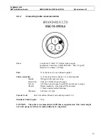
Page 16: ...he above Pairs Items 1 3 cabled together Binder Wrapped with polyester tape Drain wire 0 6mm 19 0 2mm tinned copper Screen 0 127mm tinned copper braid 84 minimum coverage Sheath Black irradiation cross linked ZX elastomer 1 15mm nominal radial thickness Diameter 8 05mm 0 5mm Colour Code Pair Cores Blue Brown and number printed 1 to 3 Maximal Cable Length 20 m CAUTION The cable is recommended to fu...

Page 17: ... the Reader is uncritical The Tags can be mounted on any flat surface If it is to be expected that the mounting surface material when warmed up can expand in a different way than the Tag the Tag must be mounted in such a way that the material expansion does not damage the Tag When screwing the Tags directly on to a surface the screw must not be secured by pulling it until it does not move anymore ...

Page 18: ...ected to make a connection unexposed to dust wet and insensitive to vibrations Pin configuration on S1501 03 Female Power Supply Connector PIN P DC power 12 V PIN R DC power 0 V DC Ground via a Y capacitor and a resistor to casing Se Earthing requirements RS232 communication port CAUTION is used only for test purpose Connector PIN A Tx 232A PIN B Rx 232A PIN C GND 232A internally connected to DC P...

Page 19: ...RTHING REQUIREMENTS Manual issue 01 19 11 EARTHING REQUIREMENTS This picture describes where to connect cable screen and ground CAUTION Cable screen and ground should be connected to this point External and Cable Grounding Point M8 thread ...

Page 20: ...ctual Reader is a standard S1566 equipped with Solid software this can be made by using the TagMaster test software ConfiTalk Commander which can be used for any Reader where the resident software was developed using ConfiLib and where ConfiTalk is enabled for example the S1501 with Solid software A final verification should be made using the actual host project software 12 3 2 Reader Tag communic...

Page 21: ...ng surface such as a road or floor the multipath effect can increase the reading distance Since the multipath effect may as well reduce the lobe width a repetitive Tag read test is recommended to check the communication in such installations If Tags are passing at a close distance from the Reader it might be necessary to reduce the reading range to avoid unwanted readings of remote Tags The range ...

Page 22: ...A or B requires intelligent converters i e converters that can switch between receive and transmit dependent of the information flow direction 13 3 Interference If more than one Reader is used in closed vicinity of each other they must be set to different RF channels Neglecting to do this will reduce communication range 13 4 Using wrong address When many Readers are controlled by one host in a pol...

Page 23: ...st case the Reader does not work at all The power supply used for a TagMaster Reader must deliver a DC power according to following specifications Power supply type Voltage limits min DC current 24VDC 20 28 Volt 200 mA 12VDC DEFAULT for S1566 10 14 Volt 550 mA The voltage from the power supply must stay within the specified limits all the time This also includes a possible ripple voltage from the ...

Reviews: