background image

6

Front Panel - PC Card 

(PCMCIA)

 Reader


The 2000I-DP is equipped with a Fortezza compliant PC Card reader located on

the front panel. TAG has configured the reader with SCSI #3. Refer to page 10 for all
SCSI IDs. The reader contains two slots which is designed to accept Type I, Type II,
and Type III card types. The upper card slot accepts only Type I and Type II cards. If a
Type III card is placed in the lower card slot of either PC Card reader, the upper slot is
not available.

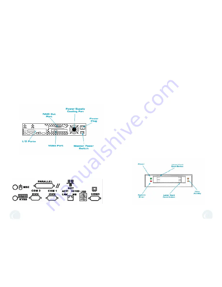
    The PC Card reader is equipped with four LED indicators and two card eject
buttons, (See

 Figure 7). 

The upper card eject button is on the left side of the slots

and the lower card eject button is on the right side of the slots.
The green LED on the left side of the unit indicates power is being supplied to that
unit. The red LED, positioned below the power indicator, will illuminate for one of
the following three reasons:

No card is inserted. When a card is inserted correctly, the red LED turnsoff.

A slot is accessed in which no card is inserted. The red LED remains lit until the
card in the other slot is accessed.

A card is inserted, but it cannot be accessed by the PC Card reader. This error can
have various causes; for example, the unit is attempting to write data to a write-
protected, a read-only, or an unknown I/O card or a hardware error exists on the
card.

The amber LEDs, on the right side of the PC Card reader, are the access indicators
for the upper and lower slots. The LED will illuminate when there is data activity on
the PC Card bus.

2000I-DP Rear Panel


The connectors for all of the external peripherals are located on the left side

of the rear panel of the 2000I-DP, 

(See Figures 14 & 15)

. When connecting

peripherals, make sure the connectors are well seated in the port.
         The main system power switch is located below the power supply on the
right side 

(See Figures 14 & 16)

. Refer to page 7 for more information regarding

the power supply. When mounting both the 2000I-DP and the HDIT-108R into a
rack, please make sure all connections are secured in their appropriate ports
before sliding the unit into the rack.

3

Figure 7

Figure 14

Figure 15

Summary of Contents for HDIT-2000I-DP

Page 1: ...Reference Manual 22355 TAG WAY Dulles VA 20166 9310 Technical Support 877 TAG TECH 1 703 406 4516 tag com HDIT 2000I DP HDIT 108R ...

Page 2: ...the NT 4 0 Server CD in the Drive 4 Change the boot priority in CMOS so that the CD ROM is now the primary boot device 5 When NT 4 0 Server begins to load press the F6 key 6 Type S and load the MegaRAID drivers for the RAID card 7 After drivers have loaded hit Enter 8 On the 1st Setup screen hit Enter 9 Type S and load the Adaptec 7800 Ver3 02 drivers for NT When prompted select the U2 drivers for...

Page 3: ... High Density Information Technology and the TAG Ball graphic are trademarks or registered trademarks of Technology Advancement Group Inc This manual and or its contents may not be duplicated without written permission of Technol ogy Advancement Group Inc Printed in the USA 10 The The 2000I DP and the HDIT 108R features several SCSI devices each with its own unique SCSI ID See Figures 21 22 The fo...

Page 4: ...tra Wide SCSI hot swap hard drives HDIT 108R Internal SCSI PC Card Reader 48X E IDE CD ROM SCSI Linking Cable 3 5 1 44MB Floppy Drive Microsoft NT Server 4 0 RAID Drive Rebuild In the event that a hot swap drive should fail the HDIT 108R will still maintain operation of the machine but the machine is considered critical The HDIT 108R will still function at full capacity however the damaged drive s...

Page 5: ...d 512MB of RAM makes this low profile server a powerful one It is equipped with a DAT backup device a ZIP Drive LS 120 Drive Floppy Drive CD ROM and a PC Card Reader All devices are easily accessable from the front panel Connecting HDIT 108R to the 2000I DP The 2000I DP is connected to the HDIT 108R by the external SCSI connec tor See Figure 19 The server connects to the left SCSI RAID connector W...

Page 6: ...erformed in the order listed below 2000I DP Power Up Procedures System Rear Panel Power Supplies Situated on the back of both the 2000I DP and the HDIT 108R are Auto Switching 115 230VAC power supplies See Figure 16 FOr each system the system main power switch is located just beneath the power supply s cooling fan Turn off the main power switch before servicing or moving the unit Power Supply Spec...

Page 7: ... turnsoff A slot is accessed in which no card is inserted The red LED remains lit until the card in the other slot is accessed A card is inserted but it cannot be accessed by the PC Card reader This error can have various causes for example the unit is attempting to write data to a write protected a read only or an unknown I O card or a hardware error exists on the card The amber LEDs on the right...

Page 8: ...e top left drive Drive 2 is SCSI ID 1 the bottom right drive Drive 3 is SCSI ID 2 and the top right drive Drive 4 is SCSI ID 3 Refer to page 10 for all SCSI IDs In the event that one drive should fail simply remove it and replace it with a working drive To remove either drive insert the hard drive module key and turn the keylock to the unlocked position Grab the handle and slide the drive out Inse...

Reviews: