background image

mn100 Analog Display 


20 


5.4 Surface 

Mounting 

5.4.1 Where there is no access to the rear of the 

mounting surface 

Easy installation but will allow removal without gaining access to the 

boat. Position the supplied Template carefully before starting. 


1. 

Drill three 2mm holes marked “SURFACE” on the Template 

2. 

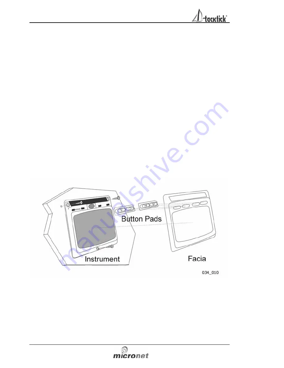
Carefully snap the facia of the instrument off the main body 

taking care not to drop the button pads.  


HINT – It may be useful to place a piece of sticky tape 
across the front of the buttons before removing the facia to 

prevent them from falling out during the installation. 

3. 

Remove the three captive M4 nuts from the plastic moulding 
and attach the instrument to the mounting surface using the 

three self tapping screws provided. Take care not to over 

tighten the screws as this may cause the moulding to crack. 

4. 

Check the instrument is perfectly level, carefully position the 
button inserts into the correct slots and snap the facia back 

into position. 


5.4.2 Temporary Mounting 

1. 

Use the double sided tape provided to secure the instrument 
to a suitable mounting surface. Press the instrument firmly 

against the surface until secure. 

Note: 

This method is recommended for temporary use only. 

 Operation 


 5 


2 – Operation 

  Important: 

Ensure that the “Auto Network” procedure described on the yellow 

instruction sheet and full Setup and Calibration has been performed 

correctly before attempting to use your Micronet instruments for 
navigation purposes. 


2.1  Instrument Display Information 


Summary of Contents for micronet mn100

Page 1: ...mn100 Analog Display uu040 rev 8 ...

Page 2: ...nstallation is required to ensure that performance is not compromised Important Due to the wireless communication systems used in Micronet instruments they are only recommended for use on boats up to 14 meters 45 ft which are of glass carbon or wooden construction Like any other Electronic instruments your Micronet system is designed to serve only as an aid to navigation and it remains the skipper...

Page 3: ...tion 10 3 Setup and Calibration 3 1 Entering Setup and Calibration Mode 12 3 2 Chapter and Page Setup and Calibration 12 3 3 Editing Values 15 3 4 Setup Page Description 14 4 Seatrial and Calibration 4 1 Wind Angle and Speed Calibration 16 5 Installation 5 1 Tools List Parts 18 5 2 Precautions and Positioning Advise 18 5 3 Bracket Mounting 19 5 4 Surface Mounting 20 5 5 External Power Connections ...

Page 4: ...ay 7 nights at brightest backlighting 20 nights at economy backlighting without charge Units of display Wind Speed knots meters per second Beaufort Alarm Audible Alarm for Wind Weight 285g 0 63lbs Operating Temp 100 to 600C 140 to 1400F Frequency 868 MHz or 905 MHz 1 3 Power Management and Battery Life What makes your mn100 instrument possible is Tacktick s revolutionary approach to power manageme...

Page 5: ...nlight If using the instruments at night power usage can be reduced dramatically by switching the Backlighting to level 1 or Off If Backlighting is not required on instruments located below decks it is best to set them to Local Backlighting control see page 15 s6 so that power is not being wasted in instruments which may not be visible from the one being viewed If the internal battery is fully cha...

Page 6: ...unted permanently below decks it will be necessary to apply an external power source to prevent complete discharge of the built in battery Connections on the rear of the instrument allow a 9V to 24V DC power source to be connected Connections can be made to the vessels DC system or a 9V battery pack may be connected It is recommended that permanent connection is only made when the instruments are ...

Page 7: ...that the Auto Network procedure described on the yellow instruction sheet and full Setup and Calibration has been performed correctly before attempting to use your Micronet instruments for navigation purposes 2 1 Instrument Display Information ...

Page 8: ...ny stage of the instrument s operation press and hold for 2 seconds the button to access the lighting control Pressing the and buttons will scroll through setting OFF 1 2 and 3 whilst changing the Backlighting Depending on the instrument setup see page 16 s5 Backlighting on the whole system or just the single instrument will be altered Backlighting is automatically switched off in daylight as part...

Page 9: ...ime a button is pressed A second beep is issued after a 2 seconds hold down of the button Alarm Continuous bursts of three beeps will indicate an alarm The alarm activated will be indicated on the digital display accompanied by the flashing symbol Pressing any button will silence the alarm Timer A single beep will be issued at each minute of the countdown With 1 minute left to go a beep will sound...

Page 10: ...age Operation Instrument information is displayed in a Chapter and Page format using the button to scroll through the Chapters and the and buttons to move between Pages The diagram below shows the information format Default Chapter Selection ...

Page 11: ...n scrolling through the Chapters the Page last selected in that Chapter will be displayed Both Chapter and Page selection will scroll back to the first Page once a cycle has been completed Page Selection For a full description of each page refer to items 1 to 8 on the following pages ...

Page 12: ... The True Wind Speed with respect to the vessel calculated by the instrument taking into account the vessels speed through the water Both Apparent Wind Speed Angle and Boat Speed must be available for this calculation Magnified Wind Chapter 3 Magnified Apparent Wind Angle The Actual Wind Angle with respect to the vessel as measured by the Wind Transmitter and displayed on a 0 to 60 degree scale an...

Page 13: ...o the ground calculated by the instrument taking into account the vessels speed through the water Apparent Wind Speed Angle Boat Speed and Current Heading must be available for this calculation Heading Chapter 7 Analogue Pointer Indicating the direction of North and Magnetic Heading Current Magnetic Compass Heading of the vessel as measured by the Compass Transducer The value displayed will be aff...

Page 14: ...tton 3 2 Chapter and Page Setup and Calibration Instrument Setup and Calibration is displayed in a Chapter and Page format using the button to scroll through the Chapters and the and buttons to move between Pages The diagram below shows the information format Note Unlike normal operation you must scroll to the Chapter heading page before moving to another chapter ...

Page 15: ...Setup and Calibration 13 Editing Values To adjust any settings press the button The setting will start to flash and the and buttons will change the value ...

Page 16: ...ut Slow Normal Fast s3 Wind Angle Offset Aligns the displayed apparent wind angle with the actual wind direction with respect to the boat See page 18 for calibration s4 Wind Speed Calibration Factor Adds a percentage factor which corrects the information from the Wind Transmitter and ensures the Apparent Wind Speed is displayed correctly See page 18 for calibration Options Chapter Press the button...

Page 17: ...0 V no Displays the instrument s Software Version battery level and charge rate to assist in troubleshooting and fault finding If the instrument is the Master the one used to switch on the system then the number of items nodes in the system will be displayed If the instrument is a Slave was switched on by the system then the signal strength to the Master will be displayed s11 HULL Shows the signal...

Page 18: ...d to ensure that readings from the Wind Transmitter are displayed accurately 4 1 1 Wind Angle Offset Motor the vessel directly into the wind Press and hold the button for 2 seconds to enter Setup Press the button repeatedly to scroll to the SETUP WIND Chapter Press the button to advance to WIND 0000 Page Press the button to enter Edit Mode Press the or buttons to change the displayed value to 000 ...

Page 19: ...rrect windspeed is available Press and hold the button for 2 seconds to enter Setup Press the button repeatedly to scroll to the SETUP WIND Chapter Press the button to advance to WIND 0 Page Press the button to enter Edit Mode Press the and buttons to change the displayed value to the required percentage The bottom digits will indicate the displayed Wind Speed Press the button to exit Edit Mode Pr...

Page 20: ...g surface is flat Leave space between instruments for sun covers Leave space to remove instrument from bracket if used Avoid areas where damage may occur winch handles feet warps etc Select a flat smooth surface for mounting and use the Template provided to select a suitable position for mounting your Micronet instrument Check for clarity of vision and ease of access to the control buttons it is r...

Page 21: ...of the instrument Fig 1 2 Drill three 2mm holes marked BRACKET on the Template and using the supplied self tapping screws attach the clip bracket to the mounting surface Fig 2 3 Place the instrument flat against the bracket slightly higher than the final position and slide gently down into position There will be a small click as the bracket secures the instrument into position Fig 3 4 To release t...

Page 22: ...fore removing the facia to prevent them from falling out during the installation 3 Remove the three captive M4 nuts from the plastic moulding and attach the instrument to the mounting surface using the three self tapping screws provided Take care not to over tighten the screws as this may cause the moulding to crack 4 Check the instrument is perfectly level carefully position the button inserts in...

Page 23: ...ment is level before final tightening 5 5 External Power Connections To connect an external 9 to 24 volt power supply to the instrument head from either a portable battery or the vessel s existing power system 1 Drill two 7mm holes marked P on the Mounting Template and smooth them together with a sharp knife or small file 2 Pass the supply cable through the new hole and attach the supplied crimp s...

Page 24: ...4 hrs prior to storage 6 2 Fault Finding and Technical Support 6 2 1 Power Save Alarm sounds There has been no significant data activity on the network The alarm sounds to indicate that the instrument system will turn itself off To continue using the system press any button to cancel the alarm 6 2 2 Lost Network Alarm sounds On a single instrument this indicates that the particular instrument has ...

Page 25: ...recharge its internal battery 6 2 5 Data is shown as dashes The information is not been transmitted to the instrument displays There may be lost communication between the Wind Transmitter or Hull transmitter and the instrument displays On any Digital instrument enter setup and calibration mode page 14 and scroll through to the Health Chapter Check the signal levels of the Hull and Wind Transmitter...

Page 26: ...pplied on purchase Proof of purchase date is required for the warranty period to be valid Due to the removable nature of the Tacktick product on board service will only be available with prior consent from Tacktick or its authorized Distributors Failure within the warranty period Simply return the product to your nearest authorized Tacktick Distributor together with proof of purchase date Failure ...

Reviews: