background image

10

SECTION 5—REPLACING THE TWISTER ASSEMBLY AND TWISTER 

GEAR:

1)  Follow the instructions in Section 4 to remove the Upper Plate. 

2)  Remove the Twister Assembly from the Middle Plate.  See Figure 12. 

3)  Slide the Bushing off the end of the Twister Gear.  See Figure 11. 

4)  Using a 2mm Allen Wrench loosen the set screw on the Twister Gear.  See Figure 11 

5)  Slide the Twister Assembly from the Twister Gear.  See Figure 11. 

6)  Insert one of the Bushings and then the new Twister Assembly into either the new or used Twister Gear.  

Make sure that the flat area located on the shaft of the Twister Assembly lines up with the set screw in the 

Twister Gear. 

7)  Slide the 2nd Bushing onto the shaft of the Twister Assembly until the end of the Bushing is flush with the 

end of the Twister Assembly shaft. 

8)  Tighten the set screw using a 2mm Allen Wrench. 

9)  Insert the Twister Assembly back into the Middle Plate pushing down until it is secure. 

10) Follow the instructions in Section 4 to replace the Upper Plate. 
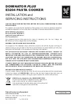
Figure 11 

Bushings 

Set Screws 

Twister Gear 

Twister Assembly 

Figure 12 

Twister Assembly 

Main Shaft 

Needle Guard Arm Spring  

Needle Guard Arm 

Needle Left 

Needle Right 

Movable Blade 

Fixed Blade 

Summary of Contents for TWISTERS 3567

Page 1: ...1 TACH IT MODEL 3567 SEMI AUTOMATIC TWIST TIE MACHINE REPAIR MANUAL 01 05...

Page 2: ...MACHINE SECTION 7 REMOVING AND REPLACING OF BOTTOM PLATE SECTION 8 LUBRICATING THE NEEDLE ARM AND NEEDLE CAM SECTION 9 REPLACING OF THE MOTOR CAPACITOR SAFETY INTERLOCK ON OFF SWITCH AND FUSE HOLDER S...

Page 3: ...raight up To replace the Top Cover 1 Locate the Safety Interlock Opening located at the back of the plate See Figure 2 2 Locate the Safety Interlock Bar mounted to the underside of the Top Cover See F...

Page 4: ...in the upper plate and also sits slightly higher than the plate Please note this position prior to removal so that it can be verified that the Fixed Blade is in the proper position prior to re assemb...

Page 5: ...egs of openings of the Twister Assembly are in a vertical position 2 Holding the Feeding Roller and the Segment Gear align them so that the flat of the Feeding Roller is against the Flat of the Segmen...

Page 6: ...Collar located directly beneath Remove Screw Upper Holding Plate Spacer Collar located directly beneath Upper Holding Plate Figure 8 Arm Spring Main Shaft Micro Switch This shows the Flats of the Seg...

Page 7: ...assembly intact to the side 8 Remove the Arm Spring See Figure 9 9 Locate the Tie Feeding Roller Arm See Figure 9 10 Locate the Screw and remove the Tie Feeding Roller Arm 11 Below the Tie Feeding Rol...

Page 8: ...TINUED Figure 9 Arm Spring Micro Switch Switch Lock Lever Spring Assembly Ground Wire and Screw Tie Feeding Roller Arm Tie Feeding Roller and Bushing Figure 10 Remove screw Remove screw Remove screw R...

Page 9: ...rmally Open terminal this is the terminal next to the empty terminal and the wire marked R3 goes to the Common terminal this is the terminal offset from the other ones 7 Re install the ground wire 8 R...

Page 10: ...ew or used Twister Gear Make sure that the flat area located on the shaft of the Twister Assembly lines up with the set screw in the Twister Gear 7 Slide the 2nd Bushing onto the shaft of the Twister...

Page 11: ...crews that hold the Twisting Head Assembly to the Base of the machine See Figure 13 8 Loosen the 3 screws Suggestion Do not remove these 3 screws just loosen them completely This way they will be in t...

Page 12: ...rew Remove screw Remove screw TIE FEEDING ROLLER ARM AND TIE FEEDING ROLLER WITH BUSHING HAVE BEEN RE MOVED IN ABOVE FIGURE SECTION 6 REMOVING AND REPLACING THE TWISTING HEAD ASSEMBLY FROM THE BASE OF...

Page 13: ...le Cam is stuck to the Bottom Plate remove it and put it back onto the Main Shaft in the same direction as it came off It is very important that it is in the same direction Make sure that the Needle C...

Page 14: ...CTION 7 REMOVING AND REPLACING OF BOTTOM PLATE CONTINUED Figure 14 Remove screw Remove screw Remove screw Remove screw Main Shaft Gear Figure 15 Needle Arm Main Shaft Needle Cam Movable Blade Remove s...

Page 15: ...cause parts to not run smoothly against each other Only lubricate using the manufacturer s specified lubricants and in the shown locations 1 Remove the Bottom Plate of the Twisting Head Assembly as p...

Page 16: ...ve the wires to the Motor one by one installing them into the new Motor 5 Remove the Main Shaft Gear by loosening and removing the Set Screw and install the Main Shaft Gear onto the new Motor Make sur...

Page 17: ...the tab at the end of the Fuse Holder 3 Unscrew the old Fuse Holder and replace it with the new Fuse Holder 4 Replace the wires making sure the wire R1 goes to the middle tab and wire R0 goes to the e...

Page 18: ...AFETY INTERLOCK ON OFF SWITCH AND FUSE HOLDER CONTINUED Remove screw Remove screw Remove screw Remove screw Figure 19 On Off Switch Motor Perforated Plate Capacitor Fuse Holder Safety Interlock Not vi...

Page 19: ...SECTION 9 REPLACING OF THE MOTOR CAPACITOR SAFETY INTERLOCK ON OFF SWITCH AND FUSE HOLDER CONTINUED Figure 20 Motor Screw Motor Screw Motor Screw Motor Screw Safety Interlock Screw Safety Interlock Sc...

Page 20: ...hine back to the Micro switch It is the assembly that moves when a bag is inserted into the tying aperture and triggers the Micro Switch to be gin the next cycle See Figure 21 If this becomes dirty or...

Page 21: ...e this protrusion with medium weight machine grease Switching Arm Switch Lever Spring Figure 21 C Clip C Clip located under Switch Lever Spring Rollers and washers Located below the C Clips Tying Aper...

Page 22: ...n Do not pull if it breaks the piece left in the machine will need to be removed Pull gently until all the ribbon is out and then re feed The Machine does not cycle properly or stops mid cycle Check i...

Reviews: