


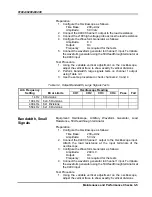
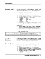
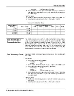

9100A/9200A/9400
Introduction and Operating Instructions 2-11
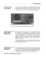
connectors
8. Using standard BNC to BNC cables (not supplied with the
instrument), connect the terminals to your load
9. (Optional step) Using standard BNC to BNC cables (not
supplied with the instrument), connect the rear panel output
monitors to a sensing device. Sensing device could be such
as an oscilloscope, DMM, digital recorder, or any other
sensing device, as long as its input impedance matches the
impedance as specified in Appendix A of this manual
WARNING
The following steps involve application of high
voltage to the output terminals. Voltage level could
be lethal, if any of the output wires is being
touched. Always keep safety distance from the
9400, its output terminals and the high voltage
path to the load circuit when high voltage is turned
on.
10. Note the warning above and flip open the high voltage safety
latch on the high voltage switch
11. Flip the high voltage switch to its ON position and note that
the front panel High Voltage ON light illuminates. Amplified
signal is now available at the load circuit and the signal itself
can be monitored on the rear panel connectors
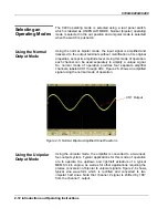
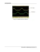
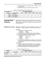
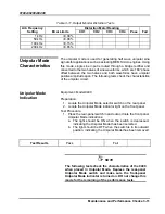
Operating Modes
The amplifier can be used in one of two modes of operation. The
first is normal mode where each channel amplifies and outputs
bipolar signals. The second mode of operation is the unipolar mode
where the signal is applied to one input, rectified, amplified and
output through two separate outputs. Description how to select the
operating mode and how to use the 9400 in each mode is given
below.


