background image

ii 

Chapter 3 - MAINTENANCE, PERFORMANCE CHECKS and ADJUSTMENTS


What’s in This Chapter ..................................................................................................................................... 3-1 

Performance Checks ........................................................................................................................................ 3-1 

Environmental Conditions................................................................................................................................. 3-1 

Warm-up Period................................................................................................................................................ 3-2 

Recommended Test Equipment ....................................................................................................................... 3-2 

Test Procedures ............................................................................................................................................... 3-2 

Amplifier Gain Accuracy ................................................................................................................................... 3-3 

Gain Accuracy Tests .................................................................................................................................... 3-3 

Amplifier Bandwidth .......................................................................................................................................... 3-4 

Bandwidth, Large Signals ............................................................................................................................ 3-4 

Bandwidth, Small Signals............................................................................................................................. 3-4 

Amplifier Pulse Response ................................................................................................................................ 3-5 

Rise/Fall Time Tests..................................................................................................................................... 3-5 

Overshoot Tests ........................................................................................................................................... 3-6 

Amplifier Distortion............................................................................................................................................ 3-6 

Distortion Tests ............................................................................................................................................ 3-6 

Adjustments Procedure .................................................................................................................................... 3-8 

Introduction ....................................................................................................................................................... 3-8 

Performance Checks ........................................................................................................................................ 3-8 

Environmental Conditions................................................................................................................................. 3-8 

Required Equipment ......................................................................................................................................... 3-9 

Initial Checks .................................................................................................................................................... 3-9 

Calibration Procedures ..................................................................................................................................... 3-9 

Gain Adjustment........................................................................................................................................... 3-9 

Bandwidth Adjustment ............................................................................................................................... 3-10 


Appendix A - SPECIFICATIONS

.................................................................................................................

A-1 


Summary of Contents for 9100A

Page 1: ...r Electronics Ltd Tabor Electronics Ltd P O Box 404 Tel Hanan Israel 20302 Tel 972 4 821 3393 FAX 972 4 821 3388 PUBLICATION DATE January 26 2009 Copyright 2006 by Tabor Electronics Ltd Printed in Isr...

Page 2: ...epresentatives and to users of its product and to any other person or persons for special or consequential damages of any kind and from any cause whatsoever arising out of or in any way connected with...

Page 3: ...sion cord or a three prong two prong adapter This will defeat the pro tective feature of the third conductor in the power cord Maintenance and calibration procedures sometimes call for operation of th...

Page 4: ...e was demonstrated to the following specifications as listed in the official Journal of the European Communities Safety IEC EN 61010 1 2nd Edition 2001 C1 C2 EMC EN 50081 1 Emissions EN 55022 Radiated...

Page 5: ...2 1 Introduction 2 1 Conventions Used in this Manual 2 4 9100A 9200A 9400 Feature Highlights 2 5 Options 2 5 Manual Changes 2 5 Specifications 2 5 Front Panel Controls and Indicators 2 6 Mains Power...

Page 6: ...Tests 3 3 Amplifier Bandwidth 3 4 Bandwidth Large Signals 3 4 Bandwidth Small Signals 3 4 Amplifier Pulse Response 3 5 Rise Fall Time Tests 3 5 Overshoot Tests 3 6 Amplifier Distortion 3 6 Distortion...

Page 7: ...3 3 Output Bandwidth Large Signals Tests 3 5 Table 3 4 Output Bandwidth Small Signals Tests 3 6 Table 3 5 Rise Fall Time Tests 3 6 Table 3 6 Overshoot Tests 3 7 Table 3 7 Distortion Tests 3 8 Table 3...

Page 8: ...iv This page intentionally left blank...

Page 9: ...uires normal precautions and procedures applicable to handling of sensitive electronic equipment The contents of all shipping containers should be checked for included accessories and certified agains...

Page 10: ...The 9400 is intended for indoor use and should be operated in a clean dry environment with an ambient temperature within the range of 0 C to 40 C WARNING The 9400 must not be operated in explosive dus...

Page 11: ...r system Crest factor ratio of peak voltage to rms should be typically within the range of 1 3 to 1 6 at 10 of the nominal rms mains voltage WARNING DO not connect the line cord to the 9400 before you...

Page 12: ...ocal Tabor representative or the Tabor Customer Service Department 1 Repack the instrument using the wrappings packing material and accessories originally shipped with the unit If the original contain...

Page 13: ...bout 1 5 inches of ventilation space on all sides of the instrument Rack Mounting The 9400 can be rack mounted inside a standard 19 rack It can be mounted using one of two configurations 1 single or 2...

Page 14: ...9100A 9200A 9400 1 6 Installation Figure 1 1 Dual Rack Mounting Option...

Page 15: ...s and features except the 9100A is a single channel version the 9200A is a dual channel version and the 9400 has four channels NOTE This manual is common to Models 9100A 9200A and Model 9400 All instr...

Page 16: ...nnel can be used separately to amplify a unique signal The second mode of operation is the unipolar mode where the signal is applied to one input rectified amplified and output through two separate ou...

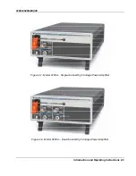
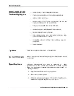
Page 17: ...9100A 9200A 9400 Introduction and Operating Instructions 2 3 Figure 2 1 Model 9100A Single channel High Voltage Power Amplifier Figure 2 2 Model 9200A Dual channel High Voltage Power Amplifier...

Page 18: ...ear in this manual NOTE A Note symbol contains information relating to the use of this product CAUTION A Caution symbol contains information that should be followed to avoid personal damage to the ins...

Page 19: ...ctive caps prevent accidental shock hazards Compatible with any of the Tabor arbitrary waveform generators Small case size Options There are no options offered with the model 9400 Manual Changes Manua...

Page 20: ...he output terminals One can turn on the power to the output terminals only by lifting the safety latch and switching the high voltage on with the HI V switch High voltage on is indicated by a clear li...

Page 21: ...m 200 V to 200 V with continuous currents up to 50 mA Outputs When used in normal operating mode Unipolar light is off the 9400 can be used as four independent amplifier channels so each of the output...

Page 22: ...ct the mains cable to the wall socket make sure the AC Voltage Selector switch is set to the correct voltage setting as required for individual countries Information how to install the instrument and...

Page 23: ...the following The Model 9400 is operating in normal mode when the switch is set to its outside position The instrument is operating in unipolar mode when the switch is pushed in and the front panel Un...

Page 24: ...ltage path to the output connectors will be blocked when power is applied to the amplifier 2 If you intend to operate the amplifier using its standard bipolar operating mode make sure the rear panel s...

Page 25: ...ys keep safety distance from the 9400 its output terminals and the high voltage path to the load circuit when high voltage is turned on 10 Note the warning above and flip open the high voltage safety...

Page 26: ...ly to amplify a unique signal So normal mode of operation provides four separate amplifier channels labeled CH1 through CH4 Figure 2 5 shows an amplified signal using the normal mode of operation CH1...

Page 27: ...9100A 9200A 9400 Introduction and Operating Instructions 2 13 CH1 Output CH2 Output Figure 2 6 Amplified Unipolar Sine Waveform...

Page 28: ...9100A 9200A 9400 2 14 Introduction and Operating Instructions This page was intentionally left blank...

Page 29: ...el Many of the steps covered in this section may expose the individual to potentially lethal voltages that could result in personal injury or death if normal safety precautions are not observed CAUTIO...

Page 30: ...erve that the High Voltage On light turns off Recommended Test Equipment Recommended test equipment for troubleshooting calibration and performance checking is listed in Table 3 1 below Test instrumen...

Page 31: ...o potentially lethal voltages that could result in personal injury or death if extreme safety precautions are not observed Do not attempt to perform any of the following tests except if you were train...

Page 32: ...erator to Channel 1 input Terminate the waveform generator using the 50 feedthrough terminator at the 9400 input Test Procedure 1 Perform Gain Accuracy tests on channel 1 output using Table 3 2 2 Use...

Page 33: ...channels 2 3 and 4 Table 3 3 Output Bandwidth Large Signals Tests Arb Frequency Oscilloscope Reading Setting Error Limits CH1 CH2 CH3 CH4 Pass Fail 1 kHz 6 Divisions 100 kHz 6 0 5 Divisions 400 kHz 6...

Page 34: ...ad Resistance x100 high voltage probe 50 feedthrough terminator Preparation 1 Configure the Oscilloscope as follows Time Base 500ns Amplitude 100 V div 2 Connect the 9400 Channel 1 output to the load...

Page 35: ...vertical trace to show exactly 6 vertical divisions 2 Perform overshoot tests on channel 1 output using Table 3 6 3 Use the same procedure to check channels 2 3 and 4 Table 3 6 Overshoot Tests Paramet...

Page 36: ...newave distortions should be very similar to those characterized by the main outputs however since the outputs are used for monitoring purpose only some of the characteristics are relaxed Each channel...

Page 37: ...for the tests 4 Connect the waveform generator to Channel 1 input Terminate the waveform generator using the 50 feedthrough terminator at the 9400 input Test Procedure 1 Using the variable vertical ad...

Page 38: ...3 10 3 Use the same procedure to check channels 2 3 and 4 Table 3 10 Output Monitor Aberrations Tests Parameter Oscilloscope Reading Tested Error Limits CH1 CH2 CH3 CH4 Pass Fail Rise Time 1 s Fall Ti...

Page 39: ...k the characteristics of the unipolar circuit Unipolar Mode Indication Equipment Model 9400 Preparation 1 Locate the Unipolar Mode selector switch on the rear panel 2 Locate the Unipolar Mode indicato...

Page 40: ...and 4 Table 3 12 Unipolar Mode Gain Accuracy Tests Arb Amplitude DMM Reading Setting Error Limits CH1 CH2 CH3 CH4 Pass Fail 2 Vp p 19 30 V 2 V 4 Vp p 38 45 V 4 V 6 Vp p 57 95 V 6 V 8 Vp p 76 80 V 8 V...

Page 41: ...Performance Checks 3 13 Table 3 13 Unipolar Mode Output Bandwidth Large Signals Tests Arb Frequency Oscilloscope Reading Setting Error Limits CH1 CH2 CH3 CH4 Pass Fail 1 kHz 6 Divisions 100 kHz 6 0 5...

Page 42: ...ance Checks Do not attempt to calibrate the amplifier before you verify that there is no problem with the functionality of the product A complete set of specification is listed in Appendix A If the in...

Page 43: ...e inside of the box 2 Identify C105 Using a DMM measure the voltage drop across this capacitor Measurement should verify 12 Vdc 5 3 Lift the front panel high voltage protection latch and turn on the h...

Page 44: ...ine Bandwidth Adjustment Main Outputs Equipment Waveform Generator Oscilloscope x100 high voltage probe Load Resistance 50 feedthrough terminator Preparation use the same procedure for channels 1 thro...

Page 45: ...nerator output to the 9400 Channel 1 then 2 3 and 4 input Use 50 feedthrough terminator at the 9400 input Adjustment 1 Identify the trimmers for each channel and make the adjustments below for rise ti...

Page 46: ...9100A 9200A 9400 Maintenance and Performance Checks 3 18...

Page 47: ...idth DC to 200 kHz unipolar mode Output Characteristics General Connector BNC Impedance 0 1 Load impedance Resistive recommended for full power bandwidth spec load resistance limited by the output cur...

Page 48: ...50 VA 120W Weight Approximately 14 lbs 6 5 kg Signal Ground Connected to case ground EMC Certification CE marked Reliability MTBF per MIL HDBK 217E 25 C Ground Benign Safety Designed to meet IEC EN610...

Reviews: