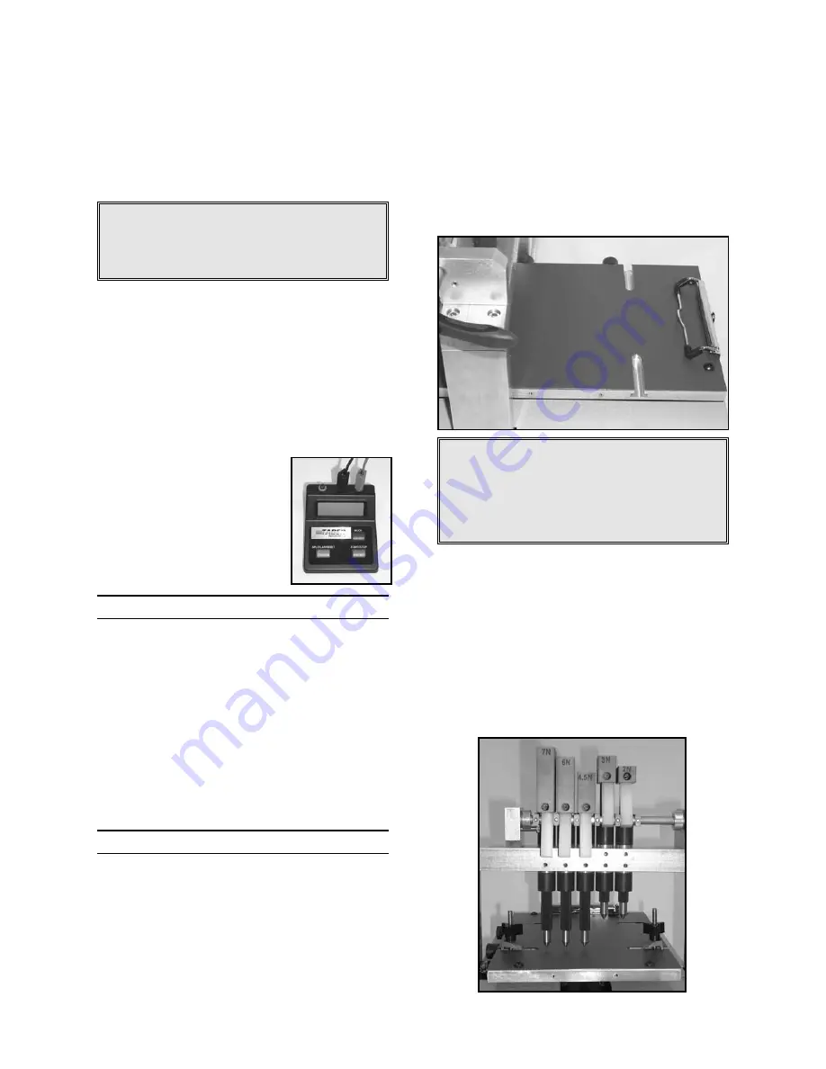
4. Select the weights to be used for testing, and
mount to the top of the spline-shaft finger.
Align so there is not any contact with the adja-
cent weight(s) and tighten in place using the
hex wrench. Weights should be mounted
from lowest to highest load, to permit ease of
evaluation.
X
WARNING: To prevent damage to the
scratch tips, turn the handle to raise the
spline-shaft fingers after the weights are
assembled.
5. Attach the quick disconnect socket (sleeve-
lock, with female ¼" NPT thread) to the air
supply hose, using Teflon tape to seal the
threads. If a local air supply is not available,
it is acceptable to use a compressor that pro-
vides 80 to 100 PSI pressure and has at least
a 2 gallon tank capacity. Fasten the hose to
the Multi-Finger Scratch / Mar Tester air
intake.
6. Connect the electronic
timer, matching the green
and black cables to their
respective sockets (the red
socket is not utilized). Insert
one AA battery, ensuring the
correct polarity.
SPECIMEN SIZE
To provide for an accurate assessment, speci-
mens should be flat panel or regions cut from a
sufficiently flat part. The recommended speci-
men size is 125mm x 300mm, with a thickness
no greater than 22mm. If taken from finished
parts, smaller or slightly contoured samples may
be used.
To test specimens that exceed the 22mm thick-
ness, spacer blocks may be inserted into the
support arms of the gantry.
OPERATING PROCEDURES
Prior to testing, it is recommended that all sam-
ples be preconditioned in a controlled atmos-
phere (such as 23 ±2° C and 50 ±5% relative
humidity) for not less than 24 hours. Samples
should be tested under the same conditions.
Conducting a Test
•
Using the handle, raise the 'fingers' to the
upright position.
•
Place a sample on the platform so the surface
to be tested is facing upward and is located
under the spline-shaft fingers. Taking care
not to deform the specimen, secure it using
the spring clamp or other specimen clamps.
X
WARNING: To prevent movement of the
specimen during testing, ensure the specimen
contacts a 'stop plate'. The spring clamp can
serve this purpose when mounted on the end
of the platform. The stop plate should be locat-
ed on the opposite side of travel.
•
If not already done, install the appropriate
scratch (mar) tips and weights.
•
Using the red button reset the electronic timer.
•
Lower the scratch (mar) tips onto the speci-
men surface and actuate the moveable plat-
form by turning the control knob in the direc-
tion the table will travel. If one or more
scratch fingers are not required, a rest block
is provided to raise the finger out of position.
3
710 Operating Instructions ver 1.1
Summary of Contents for 710
Page 10: ...NOTES ...


