


TAC Xenta 511 and 911 Handbook
3 TAC Xenta 911
TAC AB, 16 May 2003
0-004-7870-0 (EN), 27 (32)
3.4
Operation and Service
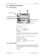
3.4.1 LED Indicators
LON Neuron status
Off
Normal Mode
Red, blinking
Unconfigured Node
Red, steady
Hardware Fault
Fail-safe state
Shorting terminals Fail-safe 9 and 10 will put the unit in “fail-safe”
state. This may be used in an emergency if the system program keeps
halting.
The position of the switch is noted directly after powering on.
Overall status indicator
Green, steady:
Program in normal mode
Green, blinking:
Program in start mode
Red, steady:
Fail-safe mode (see description above)
Red, blinking:
Unit error
3.4.2 Service Utilities
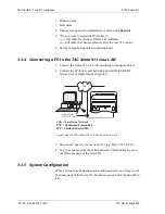
System service functions are available using the web browser and are
situated under the Utilities menu. They are primarily intended to pro-
vide technical information about the system and its status, and they can
be printed to a file or a printer.
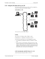
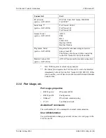
MMC
10Base-T
A RS232 B
LON
Fail-
safe
Rx/Tx
9 10
TAC Xenta 911 status indicators
Rx indicator RS232 B (yellow)
Tx indicator RS232 A (yellow)
Overall Run indicator (green/red)
Neuron status (red)
Ethernet activity (yellow)
Ethernet connector
Socket for MMC memory and activity indicator (yellow)
Service Pin
Summary of Contents for TAC Xenta 511
Page 1: ...0 004 7870 0 EN 16 May 2003 TAC Xenta 511 and 911 Handbook TAC Xenta...
Page 2: ......
Page 18: ...TAC Xenta 511 and 911 Handbook 2 TAC Xenta 511 18 32 0 004 7870 0 EN TAC AB 16 May 2003...
Page 32: ...TAC Xenta 511 and 911 Handbook 3 TAC Xenta 911 30 32 0 004 7870 0 EN TAC AB 16 May 2003...
Page 34: ...TAC Xenta 511 and 911 Handbook Index 30 32 0 004 7870 0 EN TAC AB 16 May 2003...
Page 35: ......


