SyxthSense Ltd
Online Store:
www.syxthsense.com
Copyright
©
2004 SyxthSense Ltd – 07/2004
Enquiries: T:
0870 20 80 100
F:
0870 20 80 200
PS
TH6.21
– 3/6
Operation
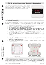
The thermostat can control either heating or cooling systems: the selection is made by setting an
internal jumper JP3 (Fig. 5).
In ‘heating’ mode the thermostat turns on the relevant channel output relay in the receiving unit when
the room temperature is lower than the value set with the knob (3) (set-point temperature). When
temperature rises over the set value the relay will be turned off. This action will be performed with an
hysteresis of 0.3°C. The hysteresis is a fixed parameter and cannot be changed.
In ‘cooling’ mode the operation logic is inverted, when temperature rises over the set value the relay
is turned on, the relay output is meant to activate a cooling system. This action will also be
performed with an hysteresis of 0.3°C. In both modes a night reduction of 3°C is available: this option
can be activated through selector (1) by setting it in ‘Program’ position (i. e. the upper position). This
function makes the thermostat operates with both the ‘comfort’ and a ‘reduced’ set-point, in order to
get energy saving, for example during the night. In ‘heating’ mode the reduced set-point corresponds
to the comfort set-point minus 3°C. In ‘cooling’ mode the reduced set-point corresponds to the
comfort set-point plus 3°C.
When in ‘Program’ position the thermostat sends to the receiver an additional signal which lets the
receiver drive the relay output in a reduced way. This signal is called ‘reduced signal’ while the
normal signal is called ‘comfort signal’. The receiving unit can then use either the signals to drive the
relevant output.
A special input (clock input) at the receiving side makes the output be controlled from the comfort or
the reduced signal. This ability was meant to easily get a reduction during the desired hours by
connecting a clock switch to the receiver.
If there is no clock connected to the receiver, the ‘Program’ position in the thermostat will operate
with the reduced set-point at any time. For more information see the receiver documentation.
Setting selector (1) in the Comfort (i.e. the central) position will make the thermostat regulate always
at the comfort set-point without any reduction. The Off position of the selector will always keep the
relevant relay output in the Off state. Note that even in the Off mode the thermostat still transmits to
the receiver signals, which will be always Off signals. This is performed to distinguish from normal
turned off operation and the eventuality of faults on the transmitter.
The thermostat is supplied with two AAA 1.5V= alkaline batteries and the red led (2) informs when
the batteries are discharged and must be replaced. In normal operation the led is always off; on the
other hand when it indicates the low battery state it flashes once every about 20 seconds. In order to
grant a reasonable battery life the thermostat waits, between two consecutive transmissions, an
amount of time that can be set in 3 or 10 minutes by moving an internal jumper JP2 (see Fig. 5). The
3 minutes option is selected by removing JP2: this option should be chosen only with fast
heating/cooling systems. With common heating systems like floor heating systems, the 10 minutes
interval option provides a good accuracy and comfort.
System Start-Up
Before installing the thermostat in the desired position, is necessary to test if the receiver unit
correctly receives its radio signals. To do this the thermostat must be turned on in a ‘Test’ mode.
The operation is described in the following.
Open the thermostat box according to the instruction in the “Mechanical description” section. Set the
appropriate address in the dip switch (10) visible in Fig. 5. The address can be chosen randomly but
taking into account that several thermostats installed in the close area must operate with different
addresses, to avoid data collision and malfunction.
See also appendix A for more information.
Insert the batteries, carefully respecting the polarity and do not use old, used, or non alkaline
batteries. When inserting the batteries for the first time the red LED (2) turns immediately on for
about 2 seconds. This displays the correct insertion of the batteries and the correct operation of the
thermostat (this can also be obtained at any time by pressing for a while the reset button (12) visible
in Fig. 5).
In the thermostat, move the selector (1) to the OFF position and just press the ’reset’ (12) button.
Now the thermostat is operating in ‘Test’ mode and this state is also displayed by the LED (2) which
flashes every 3 seconds.
During the test operation it is important not to move the selector (1), from the Off position, if it is
moved the test mode finishes. The test mode also ends automatically after about 25 minutes.