background image

32/33 | 

F-C2

Damper Inspection

The spring mechanism keeps the dampers on stand-by mode throughout their entire operational life. Without the 
producer’s permission, there must be no changes or modifications performed on the dampers’ structure.
The operator performs regular inspections of the dampers as per established regulations and standards at least once 
every 12 months. The inspection needs to be performed by an employee who has been specifically trained for this 
purpose by the manufacturer. The current fire damper condition determined during the inspection needs to be entered 
into the “Operating Journal” along with the date of the inspection, the legible name, surname and signature of the 
employee who performed the inspection. The Operating Journal includes a copy of the employee’s authorization.
If any discrepancies are discovered, these need to be entered in the Operating Journal along with a proposal for their 
removal. The Operating Journal can be found downloaded from design.systemair.com. Before the first installation, it 
needs to be inspected under the identical conditions as apply to the above mentioned 12-month inspections.
It is needed to inspect the damper’s internal casing, the thermal fuse link, the sealing, the foaming substance, the 
damper blade’s condition and its closure while it leans to a backstop in a closed position. There must be no other 
objects or dirt from the ventilation duct inside the damper.
NEVER INSPECT THE DAMPERS WHEN THERE IS AIR FLOWING IN THE DUCT SYSTEM!

Recommended Inspection Steps According to the EN 15 650:

• Date of inspection
• Check of the end switch’s connection for damage if applicable
• Check for damper cleanliness and cleaning if needed
• Check of the blades and sealing, correction and record if needed
• Check of fire damper’s safe closure – for details please see the previous section
• Check if the damper moves while being in its open and closed position, correction and record if needed
• Check of the end switch indicating the open and closed position, correction and record if needed
• Check if the damper is moved in its standard position. The F-C2 damper’s position is correct when, after the closure, 

the blades are in between the planes forming the outside surface of the wall – the ideal position is when the blade is 
in the middle between these planes.

Supplement

Any deviations from the technical specifications contained in SystemairDESIGN and the terms should be discussed
with the manufacturer. We reserve the right to make any changes to the product without prior notice,
provided that these changes do not affect the quality of the product and the required parameters.

Summary of Contents for F-C2

Page 1: ...F C2 Cartridge Fire Damper Handbook ...

Page 2: ...2 33 F C2 Table of Contents Overview 3 Technical Parameters 5 Diagrams 8 Dimensions 10 Ordering Code 11 Installation 12 Electrical Parameters 30 Operation Manual 31 ...

Page 3: ... is mechanically locked in the closed position and can only be opened manually which requires access of the maintenance staff into the duct To improve the accessibility for inspection of the fire damper a flexible duct coupling can be used Highlights Performance up to 2 hours One product fits several resistivities Closed state detection Installation with valves Product Types F C2 with size range f...

Page 4: ... substances except for the solder in the thermofuse which contains a milligram of lead Calcium silicate board is used in sizes greater than 125 mm List of installation Accessories CBR C2 Set of 4 cover boards mandatory for dry installation of F C2 FCR C2 Flexible duct connection for F C2 accessibility Detailed information about other accessories is available in SystemairDESIGN in fire damper acces...

Page 5: ...temperature Minimum 0 C Maximum 60 C for 72 C thermal fuse link Environment suitability Protected against weather disruptions with temperature above 0 C up to 95 Rha 3K5 according to EN 60721 3 3 Open Closed indication Closed indication of one blade side with micro switch Activation type H1 Closing Opening time Approximately 1 second Inspection possibility By accessing through accessory FCR C2 Or ...

Page 6: ...lled P8 P3 P2 P9 P7 P5 P6 P4 P1 P8 P3 P2 P9 P5 P6 P4 P1 P10 P10 DN140 DN200 DN80 DN125 Note Cartridge fire damper F C2 made with sheet metal blades size range from 80 mm up to 125 mm left Cartridge fire damper F C2 made with calcium silicate blades size range from 140 mm up to 200 mm right Legend P1 Casing P2 Blades P3 Thermal fuse link P4 Blades spring P5 Detent spring P6 External peripheral seal...

Page 7: ...emperature Response delay response time Pass closure time Operational reliability Pass manual cycle 50 cycles Fire resistance Resistivity depending on installation method and situation integrity E maintenance of the cross section under E mechanical stability under E cross section under E insulation I smoke leakage S Durability of response delay Pass sensing element response temperature and load be...

Page 8: ...20 30 40 l s 20 30 50 Pa Size 80 Size 90 Size 95 25 30 35 40 45 25 30 35 40 45 25 30 35 40 45 F C2 H1 Pressure drop A weighted sound power level in dB A 50 80 100 m h 20 30 40 l s 20 30 50 Pa Size 80 Size 90 Size 95 30 35 40 45 25 30 35 40 45 25 30 35 40 45 F C2 H0 Pressure drop A weighted sound power level in dB A 100 200 300 m h 30 50 80 l s 10 20 50 Pa Size 100 Size 110 Size 120 25 30 35 40 45 ...

Page 9: ... 30 35 40 45 25 30 35 40 45 F C2 H0 Pressure drop A weighted sound power level in dB A 200 300 500 m h 50 100 200 l s 5 10 20 Pa Size 160 Size 180 Size 200 25 30 35 40 45 25 30 35 40 45 25 30 35 40 45 F C2 H1 Pressure drop A weighted sound power level in dB A 200 300 500 m h 50 100 200 l s 5 10 20 Pa Size 160 Size 180 Size 200 25 30 35 40 45 25 30 35 40 45 25 30 35 40 45 Legend ps Pa Pressure drop...

Page 10: ...140 150 160 180 200 8 8 13 8 16 3 18 8 23 8 28 8 31 3 47 0 52 0 57 0 67 0 77 0 Weights m kg DN mm 80 90 95 100 110 120 125 140 150 160 180 200 0 20 0 23 0 25 0 26 0 30 0 34 0 36 0 50 0 60 0 60 0 70 0 90 Free area Av m2 DN mm 80 90 95 100 110 120 125 140 150 160 180 200 0 003 0 004 0 005 0 006 0 007 0 009 0 010 0 010 0 012 0 014 0 018 0 023 ...

Page 11: ... H1 Spring loaded blades release by a thermal fuse link set to 72 C closed indication with one AC DC 24 V contact switch Example of the F C2 Fire Dampers Ordering Code F C2 100 H1 Cartridge fire damper nominal diameter 100 mm manually operated activation mechanism with open and closed position indication with 24 V contact microswitches Note The fire resistivity depends on the installation method ...

Page 12: ... a 100 b 100 mm 500 kg m3 360 EI 90 ve i o S EI 120 ve i o S a 150 EI 60 ho i o S c 150 EI 90 ho i o S EI 120 ho i o S 2 Dry F C2 DN80 DN125 EI 60 ve i o S a 100 b 100 360 EI 90 ve i o S EI 120 ve i o S a 150 b 150 F C2 DN140 DN200 EI 60 ve i o S a 100 b 100 EI 90 ve i o S a 125 b 125 EI 120 ve i o S a 150 b 150 3 Soft F C2 DN80 DN125 EI 60 ve i o S a 100 b 100 360 EI 90 ve i o S EI 120 ve i o S a...

Page 13: ...between the fire damper and the wall ceiling can be increased by up to 50 of the gap area The gap in the installation opening between the duct that holds F C2 and the wall ceiling can be decreased to the smallest amount possible that still provides sufficient space for the installation of the seal All F C2 dampers can be installed with the blade axis in a horizontal position or a vertical position...

Page 14: ...e side of future valve placement Additional label provided in the packaging must be applied in to the duct on the valve side Fill in the area between the wall and the damper with plaster or mortar or concrete filling F1 Let the filling harden Check the damper s functionality Insert the open fire damper into the duct with the distance of 45 10 mm from one wall edge to the damper body side with exte...

Page 15: ... Wet Installation Using Plaster Mortar Concrete Filling a Flexible plasterboard wall b Concrete masonry cellular concrete rigid wall c Concrete cellular concrete rigid floor ceiling ve Vertical supporting construction wall ho Horizontal supporting construction floor ceiling 12 5 EI60S EI90S 15 EI120S 40 EI60S EI90S 60 EI120S 100 EI60S DN140 DN200 EI90S 125 DN80 DN125 EI90S 150 EI120S 500 DN D 1 DN...

Page 16: ...DN D 1 DN 100 45 45 DN D 1 DN 100 100 EI60S EI90S EI120S mm Y1 F1 1 2 4 mm Y2 1 2 3 F1 F1 1 2 3 4 Y Y 12 5 EI60S EI90S 15 EI120S 40 EI60S EI90S 60 EI120S 100 EI60S DN140 DN200 EI90S 125 DN80 DN125 EI90S 150 EI120S DN D 1 DN 100 60 DN 60 D 1 DN 100 100 EI60S EI90S EI120S mm Y1 A2 1 2 4 F1 mm Y2 1 2 F1 3 F1 1 A2 3 4 2 Y Y A2 ...

Page 17: ...80 DN125 EI60S EI90S 150 DN140 DN200 EI60S EI90S EI120S 500 DN D1 DN 60 200 25 45 Y mm 3 2 A2 F1 1 F1 3 2 1 A2 Y Y 45 DN D1 DN 60 125 DN80 DN125 EI60S EI90S 150 DN140 DN200 EI60S EI90S EI120S Y mm 3 2 F1 1 F1 3 2 1 Y Y ...

Page 18: ...18 33 F C2 DN 60 D1 DN 60 125 DN80 DN125 EI60S EI90S 150 DN140 DN200 EI60S EI90S EI120S Y mm 3 A2 2 F1 1 A2 3 2 1 F1 Y Y ...

Page 19: ...mm 12 5 EI60S EI90S 15 EI120S 4c mm 50 EI60S DN140 DN200 EI90S 75 EI90S 90 EI120S 4d 40 mm 30 kg m3 EI60S 40 mm 80 kg m3 EI90S 60 mm 85 kg m3 EI120S 4b 4d 4c 4a 625 mm Ta 4d 4c 4a C B A ø D 1 øD1 Tb mm 100 EI60S EI90S EI120S Tc mm 125 DN80 DN125 EI60S EI90S 150 DN140 DN200 EI60S EI90S EI120S Tb 3 3 T c Damper Minimum Distances mm 200 200 75 75 ...

Page 20: ... A2 Flexible duct coupling FCR C2 return plastic or metal valve e g BALANCE E 3 Concrete masonry cellular concrete wall or ceiling 4 Flexible plasterboard wall 4a 2 layers of plasterboard fireproof plate type F EN 520 4b Vertical CW profiles 4c Horizontal CW profiles 4d Mineral wool thickness cubic density see picture ...

Page 21: ... duct Check the damper s functionality Insert the open fire damper into the duct with the distance of 45 10 mm from one wall edge to the damper body side with external gasket Apply the included additional product label to the duct or wall next to the damper insertion Close the gap between the damper and the mounting opening use CBR C2 coverplates A1 with screws F4 through pre drilled holes All the...

Page 22: ... EI90S 15 EI120S 40 EI60S EI90S 60 EI120S 100 EI60S DN80 DN125 EI90S 125 DN140 DN200 EI90S 150 EI120S 500 DN D 1 DN 100 200 25 45 D 1 DN 170 D 1 DN 120 D 1 DN 60 100 EI60S DN80 DN125 EI90S 125 DN140 DN200 EI90S 150 EI120S DN 170 DN 2 2 DN 2 85 40 25 25 25 5 ø 5 5 500 DN 200 25 45 D 1 DN 170 D 1 DN 120 D 1 DN 60 10 10 mm Y1 4 1 2 A2 A1 F3 F2 F4 mm Y2 3 1 2 A2 A1 F3 F2 F4 F2 1 A2 2 3 A1 4 mm A1 t 10...

Page 23: ...0 25 25 25 5 ø 5 5 10 10 mm Y1 4 1 2 A1 F3 F2 F4 mm Y2 3 1 2 A1 F3 F2 F4 F2 1 2 3 A1 4 mm A1 t 10 Y Y DN 170 DN 2 2 DN 2 85 40 25 25 25 5 ø 5 5 DN 60 60 12 5 EI60S EI90S 15 EI120S 40 EI60S EI90S 60 EI120S 100 EI60S DN80 DN125 EI90S 125 DN140 DN200 EI90S 150 EI120S D 1 DN 100 D 1 DN 170 D 1 DN 120 D 1 DN 60 100 EI60S DN80 DN125 EI90S 125 DN140 DN200 EI90S 150 EI120S DN D 1 DN 170 D 1 DN 120 D 1 DN ...

Page 24: ...4d 4c 4a C B A ø D 1 Tb 3 4a mm 12 5 EI60S EI90S 15 EI120S 4c mm 50 EI60S DN80 DN125 EI90S 75 DN140 DN200 EI90S 90 EI120S 4d 40 mm 30 kg m3 EI60S 40 mm 80 kg m3 EI90S 60 mm 85 kg m3 EI120S Ta Tb mm 100 EI60S DN80 DN125 EI90S 125 DN140 DN200 EI90S 150 EI120S Damper Minimum Distances mm 200 200 75 75 ...

Page 25: ...ed metal ductwork A1 Cover boards CBR C2 accessory obligatory A2 Flexible duct coupling FCR C2 return plastic or metal valve e g BALANCE E 3 Concrete masonry cellular concrete wall or ceiling 4 Flexible plasterboard wall 4a 2 layers of plasterboard fireproof plate type F EN 520 4b Vertical CW profiles 4c Horizontal UW profiles 4d Mineral wool thickness cubic density see picture ...

Page 26: ...wool filling where the future duct and hole surface will be located Immediately after the fire resistive coating is applied place the duct piece into the wall opening together with the wool filling Apply the same fire resistive coating F6 at least 2 mm thick and 100 mm wide on the exposed filling and wall edges evenly from both wall sides Check the damper s functionality Insert the open fire dampe...

Page 27: ... 150 DN80 DN125 EI120S 500 DN D 1 DN 100 200 25 45 50 50 mm Y1 A2 mm Y2 A2 F5 1 A2 2 4 F6 2 F5 4 1 F6 2 F5 1 F6 3 i 3 Y Y 12 5 EI60S EI90S 15 EI120S 40 EI60S EI90S 60 EI120S DN D 1 DN 100 45 DN D 1 DN 100 50 50 100 DN80 DN125 EI60S EI90S 150 DN80 DN125 EI120S 100 DN80 DN125 EI60S EI90S 150 DN80 DN125 EI120S 45 mm Y1 F5 1 2 mm Y2 1 2 F6 F6 F5 4 3 F5 1 2 4 F6 i 3 Y Y ...

Page 28: ...N80 DN125 EI120S 45 mm Y1 A2 2 mm Y2 2 A2 F5 1 F6 4 1 F6 F5 3 F5 1 A2 4 F6 2 3 i Y Y Opening and Wall and or Ceiling Preparations B C Ta Tb mm 100 DN80 DN125 EI60S EI90S 150 DN80 DN125 EI120S 4a mm 12 5 EI60S EI90S 15 EI120S 4c mm 50 EI60S EI90S 90 EI120S 4d 40 mm 30 kg m3 EI60S 40 mm 80 kg m3 EI90S 60 mm 85 kg m3 EI120S D 1 Ta A 4b 4d 4c 4a 4d 4c 4a 3 625 mm D 1 D1 ø D 1 Ta Tb C B A ...

Page 29: ...hick for exposed surfaces 1 Fire damper F C2 2 Connected metal ductwork A2 Flexible duct coupling FCR C2 return plastic or metal valve e g BALANCE E 3 Concrete masonry cellular concrete wall or ceiling 4 Flexible plasterboard wall 4a 2 layers of plasterboard fireproof plate type F EN 520 4b Vertical CW profiles 4c Horizontal UW profiles 4d Mineral wool thickness cubic density see picture ...

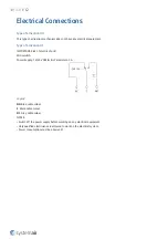
Page 30: ... H1 IMPORTANT Risk of electric shock Microswitch Power Supply 12 24V DCElectric Parameters 3A Legend NO Blue cable colour C Black cable colour NC Grey cable colour NOTES Switch off the power supply before working on any electrical equipment Only qualified electricians are allowed to work on the electrical system Power consumption must be observed ...

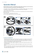
Page 31: ...re Damper Functionality Check While performing the check focus on the thermal fuse link s integrity and a correct position of the damper blades after their detention in the OPEN position they should be roughly parallel to the longitudinal axis of the duct Perform the damper activity check by taking off the thermal fuse link and releasing the blades to spontaneously close them the damper blades are...

Page 32: ... link the sealing the foaming substance the damper blade s condition and its closure while it leans to a backstop in a closed position There must be no other objects or dirt from the ventilation duct inside the damper NEVER INSPECT THE DAMPERS WHEN THERE IS AIR FLOWING IN THE DUCT SYSTEM Recommended Inspection Steps According to the EN 15 650 Date of inspection Check of the end switch s connection...

Page 33: ...Systemair DESIGN 2021 08 04 Handbook_F_C2_en GB ...

Reviews: