21/33 |
F-C2
Installation 2 - Dry
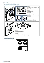
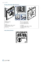
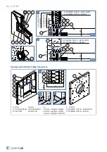
Using Mineral Wool and Coverplates
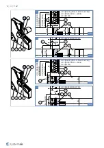
• Opening surfaces must be even and cleaned off. The flexible wall opening must be reinforced as per the standards
for plasterboard walls. Insert the open damper into the middle of the opening so that the damper blade is in the wall.
• For installation purposes, make a round opening with a diameter of DN + 60 mm into the wall.
• Insert the duct inside the middle of the opening.
Applies only for Installation with Continuous Duct:
With one end of the duct not further than 500 mm as the damper must remain accessible for installation and
inspection. Additional label provided in the packaging must be applied on the duct on the inspection side.
Applies only for Installation into the End of a Duct Fitted with Valve:
End of the duct must be aligned with the wall/ceiling surface on the side of future valve placement. Additional label
provided in the packaging must be applied in to the duct on the valve side.
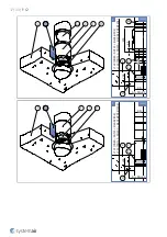
• Fill in the area between the wall and the damper with mineral wool (F2) thoroughly but in such a way that will not
deform the duct.
• Check the damper’s functionality
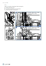
• Insert the open fire damper into the duct with the distance of 45 ± 10 mm from one wall edge to the damper body
(side with external gasket).
• Apply the included additional product label to the duct or wall next to the damper insertion.
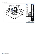
• Close the gap between the damper and the mounting opening, use CBR-C2 coverplates (A1) with screws (F4)
through pre-drilled holes.
• All the gaps between the coverplates, between coverplates and the wall and between coverplates and the duct need
to be filled with fire resistive coating (F3).
• Close off the duct with a flexible duct coupling FCR-C2 or Valve.
IMPORTANT: Make sure the valve, when inserted, is not protruding in the blade area of F-C2 damper.
Installation Distances
According to the standard EN 1366-2, the minimum distance from the wall or ceiling to the duct that holds F-C2 is 75
mm. For multiple crossings through a fire resistive wall the minimum distance between two ducts that hold F-C2 is
200 mm. This applies for distances between the duct that holds F-C2 and a nearby foreign object crossing the fire
resistive wall.
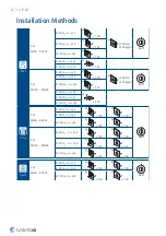
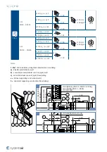
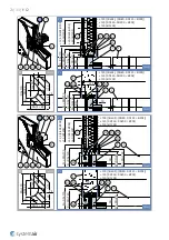
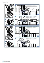
2 Dry
F-C2
DN80 ... DN125
EI 60 (v
e
i ↔ o) S
a)
≥ 100
b)
≥ 100
360°
EI 90 (v
e
i ↔ o) S
EI 120 (v
e
i ↔ o) S
a)
≥ 150
b)
≥ 150
F-C2
DN140 ... DN200
EI 60 (v
e
- i ↔ o) S
a)
≥ 100
b)
≥ 100
EI 90 (v
e
- i ↔ o) S
a)
≥ 125
b)
≥ 125
EI 120 (v
e
i ↔ o) S
a)
≥ 150
b)
≥ 150

