3.5 External connectors
3.5.1 Overview of external connections
The following illustration shows the connectors that are located on the
back of the PILOT 217 monitor/thin client.
Fig. 9: Overview of the interfaces on the back (depending on the configura-
tion)
3.5.2 Description of the external connections
Your device will not incorporate all of the following connectors (see
Ä
Chapter 3.3 “Technical data for the device” on page 13
).
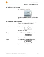
= 9-pole Sub-D socket for connecting serial devices
Fig. 10: Serial connection (RS
‑
232)
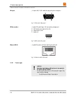
= 24-pole DVI socket for connecting to the basic computer
Fig. 11: DVI socket with pinout
= 19-pole HDMI socket for connecting to the basic computer
Fig. 12: HDMI socket with pinout
Serial connection (RS
‑
232)
DVI port
HDMI port
Product description
External connectors > Description of the external connections
PILOT 217 monitor/thin client - Industrial monitor/thin client
17
Summary of Contents for PILOT 217
Page 4: ...Table of contents PILOT 217 monitor thin client Industrial monitor thin client 4...
Page 10: ...Safety Important safety notes PILOT 217 monitor thin client Industrial monitor thin client 10...
Page 32: ...Repairs PILOT 217 monitor thin client Industrial monitor thin client 32...
Page 36: ...Storage Storing the device PILOT 217 monitor thin client Industrial monitor thin client 36...
Page 40: ...Disposal PILOT 217 monitor thin client Industrial monitor thin client 40...

