5
The BF-4-ALF/SLF is an electromagnetic feeder that
uses current to energize the electromagnet (coil) and
power the feeder. Rectified Alternating Current (AC) is
applied to the magnet assembly of the drive, pulling the
armature and entire trough assembly down and back
toward the drive during this portion of the stroke. When
the power is cycled off, the springs return the trough
assembly and drive back to the “at rest” position. The
trough assembly moves up and forward through this
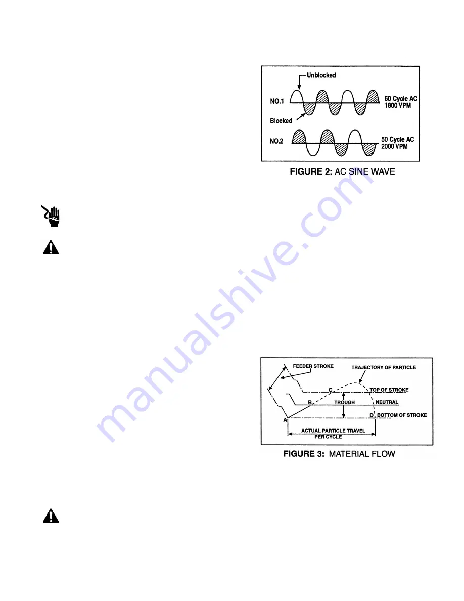
portion of the stroke.Refer to Figure 3 for the trough
description of how material conveys on the feeder.
A timing algorithm in the micro processor supplies power
to the drive at the proper voltage and freqency. The UMC
Control and drive unit can be supplied for either 50Hz or 60Hz line freqency operation.
CAUTION: Do not operate the BF-4-ALF/ASLF Feeder and control on a supply frreqency other than
designated frequency.
CAUTION: During normal operation, the feeder performs with a smooth, even stroke. If a loud
striking noise occurs, immediately turn off the unit and refer to the Air Gap Adjustment instructions in this
manual.
Using the pulsating action described above, the trough assembly moves particles being conveyed
forward, the pulls back and allows them to land downstream. Repeating this action at 1800 cycles per
minute (60Hz), or 2000 cycles per minute (50Hz) causes the material to convey smoothly along the entire
length of the trough to the discharge.
Figure 3 illustrates material flow along the trough surface. Each cycle moves the material forward and
upward, and further along toward the discharge. The rate
feed is controlled by the intensity of the magnetic pull,
which is varied by the control.
During a powered half-cycle, the trough surface travels
between its lowest point (A) to its highest limit (C). The
trough travels at its greatest velocity between (A) and (B);
although still traveling up and forward, the trough
decelerates between (B) and (C). On the upward stroke,
the particle of material is in contact with the trough from
(A) to (B). At point (B), the velocity of the particle
becomes greater than the trough, and the particle leaves the trough on a free-flight trajectory from (B) to
(D). The particle lands back on the trough surface at a position further forward (D). This completes one
cycle.
INSTALLATION
WARNING: Do not lift the feeder by the trough. This could cause the air gap to become
misadjusted and damage the trough or drive unit.


