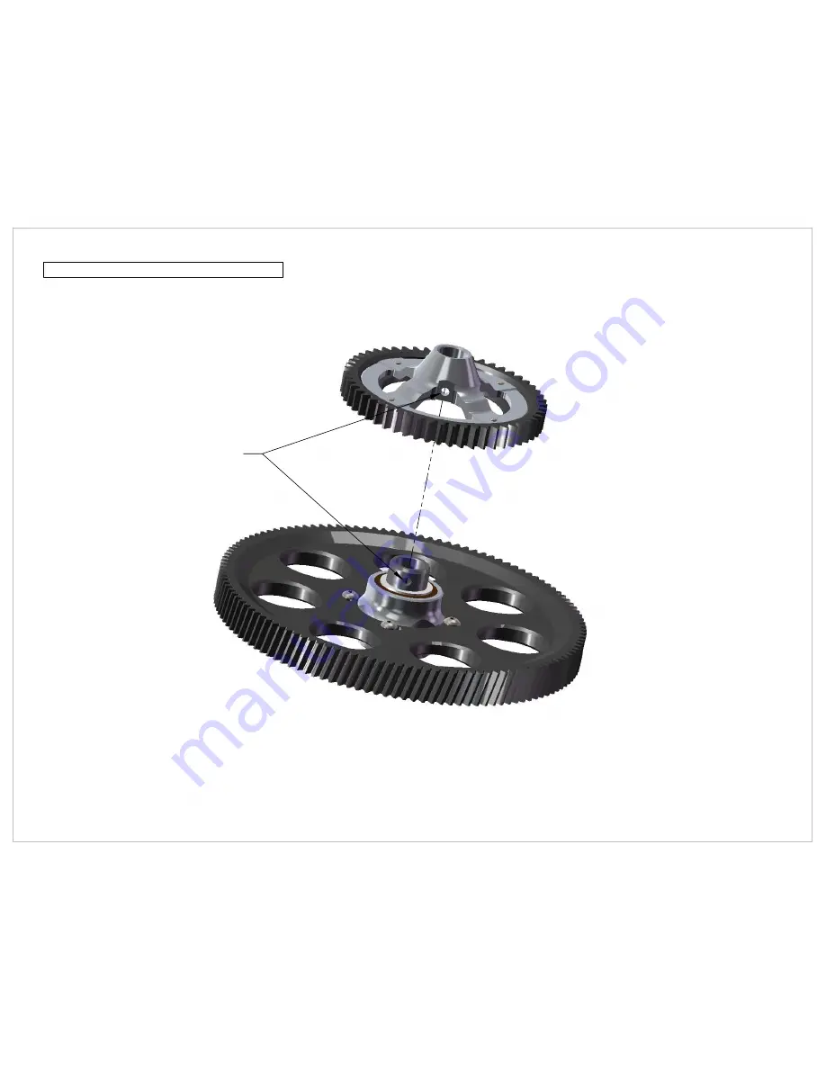
Align Holes
Main Gear to Spur Gear Assembly
Page 24
WWW.SYNERGYRCHELICOPTERS.COM
Page 1: ...D e s i g n e db y S yner g y E7S E A s s e m b l y I n s t r u c t i o n s 9 9 9 6 0 1 w w w s yner g yr ch eli cop ter s com...
Page 2: ...If you are new to the hobby we strongly recommend seeking the help and advice from an experienced modeler Operating a model helicopter requires a high degree of diligence and skill If you are new to...
Page 3: ...06 M3x6 Button Head 101 306 M3 Button Head 103 256 M2 5 Flat Head Cross Recess 310 112 Landing Gear Mount 310 110 Frame Spacer Base Plate Assembly Page 1 310 103 CF Base Plate WWW SYNERGYRCHELICOPTERS...
Page 4: ...0 Main Shaft Bearing Block E6 7 310 151 Third Main Shaft Bearing Block Important Keep this orientation in mind for future reference Make sure bearing block and bearing orientation is correct Top beari...
Page 5: ...100 306 M3x6 Socket Head 101 306 M3x6 Button Head 100 308 M3x8 Socket Head 100 306 M3x8 Socket Head 100 306 M3x8 Socket Head Left Frame Side Assembly Page 3 WWW SYNERGYRCHELICOPTERS COM...
Page 6: ...Servo Hold Down 310 100 Tail Servo Mount Tail Servo Not Included 107 104 2mm Pivot Ball 100 252 2mm Nylock Nut Important Pivot Ball should be placed at 16mm from center of servo horn Recommended Tail...
Page 7: ...M2 5x6 Flat Head 310 104 Sensor Mount Plate 310 110 Frame Spacer E6 7 Sensor Mount Assembly Lower Frame Brace Assembly 103 256 M2 5x6 Flat Head 310 110 Frame Spacer E6 7 310 105 CF Lower Frame Brace...
Page 8: ...Sensor Mount and Frame Brace Install 101 306 M3x6 Button Head This hole is for the boom supports Do not use yet Page 6 WWW SYNERGYRCHELICOPTERS COM...
Page 9: ...407 2mm Spur Gear Pin 320 111H 11T Spur Gear Hard Coat 320 408 Spur Gear Shaft 108 593 5x9x3 Radial Bearing 320 303 Spur Gear Bottom Bearing Block 320 218 18T Front Trans Mushroom Gear 101 306 M3x6 B...
Page 10: ...erent tail gear ratios 11T 4 9 1 Slide Fore 12T 4 5 1 Slide Aft Recommended Tail Ratio 4 5 1 Headspeed above 2000 4 9 1 Headspeed below 1950 Recommended Tail Blades 4 5 1 Rail 106 116mm 4 9 1 Rail 96...
Page 11: ...Right Frame Side Install 100 306 M3x6 Socket Head 100 308 M3x8 Socket Head 100 306 M3x6 Socket Head 101 306 M3x6 Button Head 101 306 M3x6 Button Head Page 9 WWW SYNERGYRCHELICOPTERS COM...
Page 12: ...spins freely within bearings If main shaft does not spin freely loosen all bolts and ensure frames are square with bearing block Secure all main frame bolts at this time Main Frame Alignment Page 10...
Page 13: ...ket head 310 107 CF Servo Arm IMPORTANT Use Red Loctite to secure Pivot Ball to M3 Nut Servo Horn Assembly Note It is best to determine servo horn position clostest to 90 degrees before fixing CF serv...
Page 14: ...cket Head Servo Horn Screw Not Included Servo Mounting Note All three cyclic servos should be installed at this point in time At a minimum the elevator servo should be installed as it may be difficult...
Page 15: ...age 13 Landing Gear Assembly Complete Landing Gear 101 308 M3x8 Button Head 610 324 Landing Gear Strut 610 322 Skid Tube Lock x4 610 321 Skid Tube 106 966 Skid Tube Plug x4 WWW SYNERGYRCHELICOPTERS CO...
Page 16: ...100 312 M3x12 Socket Head Landing Gear Install Page 14 WWW SYNERGYRCHELICOPTERS COM...
Page 17: ...101 306 M3x6 Button Head 310 108 CF Radio Plate 310 111 Main Boom Clamp E6 7 100 310 M3x10 Socket Head 310 111 Main Boom Clamp E6 7 Main Boom Clamp Assembly Page 15 WWW SYNERGYRCHELICOPTERS COM...
Page 18: ...100 308 M3x8 Socket Head 100 308 M3x8 Socket Head Main Boom Clamp Install Page 16 WWW SYNERGYRCHELICOPTERS COM...
Page 19: ...ned to accept motor with 4mm bolts and 30mm bolt pattern option 25x3mm motor mounting was left out due to weakness of the M3 bolts and increasing power of todays motors Motor shaft should be minimum o...
Page 20: ...hless Motor Install 100 312 M3x12 Socket Head 310 152 Motor Shaft Support Bearing Block 108 615 6x15x5 Radial Bearing factory installed 710 101 Motor Mount Side Plate Page 18 WWW SYNERGYRCHELICOPTERS...
Page 21: ...ESC Mount Plate Assembly Page 19 103 256 M2 5x6 Flat Head Cross Recess 310 102 ESC Mount Plate 310 110 Frame Spacer E6 7 WWW SYNERGYRCHELICOPTERS COM...
Page 22: ...100 306 M3x6 Socket Head 100 306 M3x6 Socket Head 100 372 M3x12 Set Screw 100 372 M3x12 Set Screw ESC Plate Install Page 20 WWW SYNERGYRCHELICOPTERS COM...
Page 23: ...Screw Female Canopy Mount Install 305 121 Key Chain Canopy Mount 21mm Female 305 121 Key Chain Canopy Mount 21mm Female 305 121 Key Chain Canopy Mount 21mm Female 305 121 Key Chain Canopy Mount 21mm F...
Page 24: ...x6 Type 1Cross Recess 320 154 54T Spur Gear 320 410 Spur Gear Hub Spur Gear Hub Assembly DO NOT OVER TIGHTEN Over tightening can crack the Delrin spur gear leading to failure Page 22 WWW SYNERGYRCHELI...
Page 25: ...T OIL SUCH AS TRIFLOW Important Bronze bushings must be secured with green or red loctite Note By design the auto hub is symetrical so it can be used in both orientations The One Way Clutch Bearing ca...
Page 26: ...Align Holes Main Gear to Spur Gear Assembly Page 24 WWW SYNERGYRCHELICOPTERS COM...
Page 27: ...ar Install IMPORTANT Ensure boss is facing up when installing the Jesus Bolt Collar IMPORTANT Shouldered bolts should not be tightened with force It is possible to stress the shouldered bolt 109 110 1...
Page 28: ...t Ball Long x3 107 106 Pivot Ball x4 108 373 3x7x3 Radial Bearing 100 316 M3x16 Socket Head 109 352 3x5x2 Brass Spacer 100 312 M3x12 Socket Head 100 364 M3x4 Set Screw 200 401 Swash Plate Assembly Pag...
Page 29: ...mm Shim 108 816 8x16x5 Radial 106 801 8x 5mm Shim 108 817 8x16x5 Thrust bearing 520 514 FBL Main Blade Grip 100 308 M3x8 Socket Head Rotor Head Assembly Note Thrust Bearing Order Large ID Large OD Ins...
Page 30: ...l Link 100 272 M2 5x12 Set Screw 305 207 E5 Ball Link Adapter 106 301 M3 Shim Note Do not tighten 100 323 bolt until the next page These will pinch and secure the main shaft Page 28 WWW SYNERGYRCHELIC...
Page 31: ...320A M3x20 Special Bolt IMPORTANT Do not over tighten 100 320A Bolt IMPORTANT Do not forget to tighten pinch bolts equally on both sides 27 80mm Pitch Link 107 100 Ball Link 107 048 48mm Link Rod 107...
Page 32: ...CCPM Servo Linkage CCMP Servo Linkage Install 18 20mm 107 100 Ball Link 107 100 Ball Link 107 043 43mm Link Rod Page 30 WWW SYNERGYRCHELICOPTERS COM...
Page 33: ...Head DO NOT OVER TIGHTEN 320 400 Tail Box 320 412 17mm Bevel Gear Pin 108 124 12x18x4 Radial Bearing Tail Box Assembly 100 330 M3x30 Socket Head 108 613 6x13x5 Radial Bearing 108 613 6x13x5 Radial Be...
Page 34: ...7SE Tail Bearing Ring Aluminum 107 109 Tail Pitch Pivot Ball 606 921 Tail Pitch Link Pin 115 322 Tail Pitch Link 320 321 E7SE Tail Pitch Plate Threaded 506 920 E Ring IMPORTANT Use red or green loctit...
Page 35: ...11 5x10x4 Thrust Bearing 515 525 HD Tail Blade Grip 108 503 5x10x3 Radial Bearing 107 106 Pivot Ball 615 324 HD Tail Rotor Hub Tail Thrust Bearing Note Large OD Large ID Inside Small OD Small ID Outsi...
Page 36: ...ote Sizing of ball links is recommended for smooth operation For best results use Boto Sizer Tool Part 700 001 109 355 3x5x5 Brass Spacer 106 301 M3 Shim 100 251 M2 Nut 100 351 M3 Nylock Nut 100 464 M...
Page 37: ...3mm hole at 26 5mm 3 Secure with blue Loctite and M3x6 Button Head 4 Optional but highly recommended if your tail box departs from your boom because you forgot to pinch the boom clamp you will wish yo...
Page 38: ...ess point 3 Drill 3mm hole through marked side of boom 6 5mm from edge of boom 4 Install M3x6 Button Head Bolt with blue loctite to secure boom 5 Tail Boom Fore most boom clamp 101 306 M3x6 Button Hea...
Page 39: ...ith high quality glue such as JB Weld We highly recommend long curing formulas for the best results Do not use CA for this application You will encounter failures Note Lightly sand carbon tail control...
Page 40: ...ing to Torque Tube Do not apply loctite to plastic Important Secure Torque Tube end with quality RED Loctite Note Install bearings on torque tube shaft before installing torque tube ends Bearings will...
Page 41: ...1 Use Epoxy or JBWeld 2 Ensure ends are in alignment while glue sets Top attaches to boom clamp Bottom attaches to frames Sand Ends Lightly Before applying glue Sand Ends lightly before applying glue...
Page 42: ...Note Use silicone based grease for installation of torque tube assembly into the tail boom Tail Boom Assembly Note Tail Boom will remain flush with front boom mount Do not push tail boom all the way f...
Page 43: ...Tail Box Install 101 308 M3x8 Button Head 100 308 M3x8 Socket Head IMPORTANT Do not over tighten bolts IMPORTANT Do not over tighten bolts Page 41 WWW SYNERGYRCHELICOPTERS COM...
Page 44: ...101 412 M4x12 Button Head 100 316 M3x16 Socket Head 100 354 M3 Washer Boom Support Install Page 42 WWW SYNERGYRCHELICOPTERS COM...
Page 45: ...M5x35 Socket Head M5 Nylock Nut Blade Spacers Not Included 696 716mm Main Blades Main Blade Install Blade spacers are usually included by rotor blade manufacturer Page 43 WWW SYNERGYRCHELICOPTERS COM...
Page 46: ...Head 100 351 M3 Nylock Nut Note Counter clockwise rotating tail Install tail blades as illustrated IMPORTANT Select correct tail blade size per Head Speed RPM 2000 and up 96 106mm Tail Blades 1950 an...
Page 47: ...mmet 305 125 Key Chain Canopy Mount Male Canopy Assembly Note Canopy holes may need enlarged to approximately 8 9mm in order to correctly install the canopy rubber grommet 310 405 E7SE Canopy Page 45...
Page 48: ...365 mm 1330 mm Synergy E7SE Completed Page 46 WWW SYNERGYRCHELICOPTERS COM...
Page 49: ...214 25mm 1549 500 157 500 with Rail 696 Blades Bolt to Bolt Landing Gear Width Synergy E7SE Top View Page 47 WWW SYNERGYRCHELICOPTERS COM...