background image

SynCardia Systems, LLC 
Companion 2 Driver System Operator Manual


Page 101 of 132 

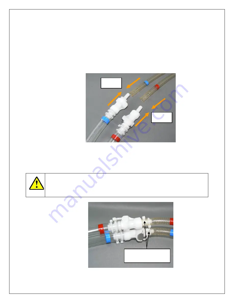
16.3.4.  Remove the metal hose barb from the red Cannula by pulling and 

then immediately insert the CPC connector of the red Companion 
2 Driveline into the red Cannula (

Figure 16-3

). 

16.3.5.  Simultaneously, remove the metal hose barb from the 

blue


Cannula by pulling and then immediately insert the CPC 
connector of the

  blue

  Companion 2  Driveline into the blue 

Cannula (

Figure 16-3

). 


Figure 16-3 – Inserting the Companion 2 Drivelines into the Cannulae 


16.3.6.  Secure each Cannula to the CPC connectors with two Wire Ties, 

as shown in 

Figure 16-4

 below. 


CAUTION 

The  Wire  Ties around the Cannulae and CPC connectors must be 
secured using a Wire Tie Gun. 


Figure 16-4 – Securing Cannulae to CPC Connectors with Wire Ties 

Push in 

Push in 

Secure each Cannula 
with two Wire Ties 

Summary of Contents for Companion 2 Driver System

Page 1: ...tificial Heart TAH t is an Investigational Device Limited by United States Law to Investigational Use CAUTION In the United States the use of the SynCardia 70cc TAH t for destination therapy is invest...

Page 2: ...SynCardia Systems LLC Companion 2 Driver System Operator Manual Page 2 of 132...

Page 3: ...Companion 2 Driver Operation Cautions 69 Chapter 13 Power Management 73 Chapter 14 Alarms and Notifications 81 Chapter 15 Switching from Primary Companion 2 Driver to Backup Companion 2 Driver 97 Chap...

Page 4: ...SynCardia Systems LLC Companion 2 Driver System Operator Manual Page 4 of 132...

Page 5: ...re 8 4 System Check Menu Screen 38 Figure 8 5 Set Date Time 40 Figure 8 6 New Patient Setup Screen 41 Figure 8 7 Patient File Copy Screen 43 Figure 8 8 Parameter Adjustment Window 44 Figure 8 9 Adjust...

Page 6: ...on Screen 91 Figure 16 1 Wire Ties around CSS Hose Barb Connectors 100 Figure 16 2 Metal Hose Barb Connectors Loosened but Still Connected to the Cannulae 100 Figure 16 3 Inserting the Companion 2 Dri...

Page 7: ...Responses 81 Table 14 2 Alarm Configuration Default Settings and Ranges 92 Table 14 3 Notifications 94 Table 22 1 Declaration Concerning General Safety Standards 121 Table 22 2 Declaration and Guidan...

Page 8: ...SynCardia Systems LLC Companion 2 Driver System Operator Manual Page 8 of 132...

Page 9: ...ation For more information on the TAH t see the SynCardia temporary Total Artificial Heart TAH t Instructions for Use with the Companion 2 Driver System for the 50cc or 70cc TAH t as appropriate The 5...

Page 10: ...ion 2 Driver System The Companion 2 Driver System Figure 1 3 is a multi component electro mechanical unit designed to provide pneumatic power to the implanted 50cc or 70cc TAH t The Companion 2 Driver...

Page 11: ...ich the Driver docks It is intended for use in the hospital during the TAH t implant procedure and subsequent recovery phase o The Driver docks into the Hospital Cart by placing the Driver straight in...

Page 12: ...res o The Driver docks into the Caddy by placing the Driver straight into the center of the Caddy so that the docking connectors mate The Driver must always be put into the Driver Caddy with the Exter...

Page 13: ...Hand Pump is designed for emergency use when a backup Driver is not immediately available The Companion Drivelines connect to the CPC connectors on the Hand Pump Clinical operators should pump at 110...

Page 14: ...SynCardia Systems LLC Companion 2 Driver System Operator Manual Page 14 of 132...

Page 15: ...ion therapy for patients who are ineligible for cardiac transplantation and for whom clinical indices indicate a remote likelihood of becoming eligible for a transplant is investigational 2 2 50cc TAH...

Page 16: ...SynCardia Systems LLC Companion 2 Driver System Operator Manual Page 16 of 132...

Page 17: ...m or who have a distance between the sternum and the 10th anterior vertebral body measured by computed tomography imaging CT scan 10 cm Patients who cannot be adequately anticoagulated on the 70cc TAH...

Page 18: ...SynCardia Systems LLC Companion 2 Driver System Operator Manual Page 18 of 132...

Page 19: ...r by x ray after catheter insertion and repeat an x ray immediately if any unexplained sudden drop in cardiac output occurs A percutaneously inserted central catheter may migrate into the inflow valve...

Page 20: ...the Companion 2 Driver versus the Circulatory Support Console CSS with the TAH t for patients who received circulatory rescue intervention e g extracorporeal membrane oxygenation ECMO or intra aortic...

Page 21: ...ver with a backup Companion 2 Driver in the event of system failure Connect the backup Companion 2 Driver as quickly as possible This procedure is for emergency use only See Chapter 15 in this manual...

Page 22: ...es is established 5 14 The level of anticoagulation will vary depending on the patient s coagulation status Clinical experience has shown that typically patients supported with the 70cc TAH t require...

Page 23: ...at is regulated to cause the left and right TAH t ventricle diaphragms to move upward and expel blood into the arterial and pulmonary systems In diastole vacuum is applied by speed regulated vacuum bl...

Page 24: ...can be loaded onto the Driver through this unidirectional USB interface A Key Switch on the front panel of the Driver allows the device to be manually stopped and started When the Driver Key Switch i...

Page 25: ...1 Display Screen The color LCD display and touch screen is the mechanism by which all adjustable device operating parameters may be adjusted and device outputs monitored and displayed The primary I C...

Page 26: ...ironment and Chapter 10 Operating Modes Ambulatory Mode The Power Status Window displays battery charge status for both external Batteries and shows a plug icon when the device is powered by an extern...

Page 27: ...ied to the Driver A yellow external power LED indicates the Driver is operating from battery power Battery LED Solid green indicates the battery is charged and has at least 20 of capacity The LEDs fla...

Page 28: ...approximately one minute to update the estimated battery support time based on Driver settings 6 5 1 Connection to External Power The Driver should be connected to external wall power via the Hospital...

Page 29: ...de is Battery 1 The Battery on the right side is Battery 2 Two fully charged Batteries provide a minimum of 60 minutes of support with each Battery providing a minimum of 30 minutes of support Actual...

Page 30: ...icate a fully charged Battery with each light representing approximately 20 capacity 6 5 3 Emergency Battery The Emergency Battery is an independent internal rechargeable lithium ion battery that does...

Page 31: ...mmended that the external air pressure for the Companion 2 Driver be between 50 to 80 PSI 3 5 to 5 5 Bar If the external air pressure is below this range it will not impact the Driver functionality ho...

Page 32: ...SynCardia Systems LLC Companion 2 Driver System Operator Manual Page 32 of 132...

Page 33: ...ver Settings is available 8 1 Preparation for Use O R Mode 8 1 1 Dock the Driver without External Batteries into the Hospital Cart If necessary this may be done with the help of another trained user 8...

Page 34: ...creen is non responsive after the graphical user interface is presented on the display dock the Driver into the Hospital Cart to recalibrate the Driver touch screen This is performed by following the...

Page 35: ...splay 2 Select MENU then O R MODE Figure 8 1 Figure 8 1 Menu Selection in Ambulatory Mode 3 A dialogue box called ENTER PASSWORD will request that you enter the O R Mode password 3228 and press CONFIR...

Page 36: ...Alarm indicator has a solid X over the speaker to indicate that audible alarms are muted A reminder audible signal will be generated every two hours to indicate that the system is in O R Mode All vis...

Page 37: ...touch screen select MENU SETUP and either DRIVER SCREEN CALIBRATION or CART SCREEN CALIBRATION 3 The onscreen prompts will direct you to touch four places in succession on the screen to be calibrated...

Page 38: ...required from initial power on to when the system begins to run at the default start up settings 5 Verify that that the Driver compressors began to run within 10 seconds and note the results on the fo...

Page 39: ...d 12 The power management system and indicators are manually verified Complete the steps and document the results on the System Check Form See Chapter 13 Power Management for any additional informatio...

Page 40: ...ent data should be downloaded Press CANCEL if you would like to exit the new patient file screen 5 Enter the patient information in the pop up window using the touch keyboard that appears Select the w...

Page 41: ...EDIT Figure 8 6 New Patient Setup Screen 10 Patient File Information Patient data log files record information pertaining to the operation of the Driver and any alarms that occurred in a comma separa...

Page 42: ...n the Alarm log This information remains stored even if power to the Driver is removed See Chapter 14 Alarms and Notifications for additional information on alarms 11 Copy Patient File The steps for c...

Page 43: ...SynCardia Systems LLC Companion 2 Driver System Operator Manual Page 43 of 132 Figure 8 7 Patient File Copy Screen...

Page 44: ...e The following actions may be required during the procedure 8 2 1 Adjustment of Operation Parameter The Parameter Adjustment Window of the user interface is shown in Figure 8 8 below Figure 8 8 Param...

Page 45: ...d Hold Increment Rate Beats per minute BPM 40 40 is single pulse mode 150 1 10 Systole Percent 40 60 1 1 Left Pressure mmHg 120 280 1 5 Right Pressure mmHg 40 150 1 5 Left Vacuum mmHg 0 30 1 5 Right V...

Page 46: ...to 40 in O R Mode Turning the rate down any further suspends pumping action and allows single pulse actuations to be used which are helpful in de airing the TAH t 1 To set the Driver to single pulse...

Page 47: ...rease the Rate select RATE and press and hold the increment button to increase the Rate to 120 BPM Multiple alarms will be displayed when transitioning out of single pulse mode These alarms will clear...

Page 48: ...acceptable partial fill is between 50 and 60 cc The fill capacity of each 50cc ventricle is 50cc acceptable partial fill is between 30 and 40 cc 8 2 4 Flip Screen The surgeon may request to see the c...

Page 49: ...the main screen display to view a larger pressure waveform graph The left pressure is shown with a red line and the right pressure waveform is shown with a blue line It may be necessary to increase or...

Page 50: ...lag is reduced to approximately 10 to 20 of the pressure waveform length 4 Partial Fill Adjustment The TAH t is intended to operate with a partial fill An acceptable partial fill for the 70cc TAH t is...

Page 51: ...ricle and blue for the right ventricle Always assure partial filling of the ventricles by observing the displayed fill volume of the ventricles and flow waveform on the screen An acceptable partial fi...

Page 52: ...is full filling See Figure 8 13 If the flow remains above zero as shown in Figure 8 14 the device is operating in a partial fill condition Note If the Flow Waveform indicates a full fill condition th...

Page 53: ...o the instantaneous Cardiac Output display to see if the current Cardiac Output is greater than or less than the hourly average cardiac output Figure 8 15 Reset Average Hourly Cardiac Output 8 2 6 Cha...

Page 54: ...Ambulatory Mode 8 2 8 Setup of Backup Driver The Driver will begin operating at default settings when power is applied and the key switch is set to the ON position The Driver will begin to pump as so...

Page 55: ...LLC Companion 2 Driver System Operator Manual Page 55 of 132 3 Change to I C U Mode by selecting MENU I C U MODE and enter the password 9722 4 Press the LOCK Icon in the lower right corner to unlock...

Page 56: ...SynCardia Systems LLC Companion 2 Driver System Operator Manual Page 56 of 132...

Page 57: ...ended to be used by trained hospital personnel who have a need to modify device operation to respond to potential changes in patient conditions such as decreasing pressure when patient edema decreases...

Page 58: ...ure 9 2 Unlocked screens revert to locked status after 30 seconds of no activity Figure 9 2 I C U Mode Screen Unlocked 9 2 Adjustment of Parameters 9 2 1 Operating parameters can be adjusted once the...

Page 59: ...parameters are adjusted as follows 1 Unlock the LOCK icon by selecting it 2 Press the RATE button on the LCD screen 3 Select or to increase or decrease the rate 4 Select to enter the change or X to ca...

Page 60: ...old Increment Rate Beats per minute BPM 90 150 1 10 Systole Percent 40 60 1 1 Left Pressure mmHg 120 280 1 5 Right Pressure mmHg 40 150 1 5 Left Vacuum mmHg 0 30 1 5 Right Vacuum mmHg 0 30 1 5 Actual...

Page 61: ...ate and Time if necessary Any other changes of device settings require that the Operating Mode be changed to I C U Mode or O R Mode When power is applied and the key switch is set to the ON position t...

Page 62: ...mma separated file CSV that can be opened with most spreadsheet applications The Patient File information includes performance data pressure and flow waveforms and alarm history data The following per...

Page 63: ...ter 14 Alarms and Notifications for additional information on alarms 10 2 Adjustments 10 2 1 Copy Patient File The steps for copying files to any 8GB or larger USB 1 0 2 0 compliant mass memory device...

Page 64: ...ent File Copy Screen 10 2 2 Set Date and Time Set the Date and Time for the Driver if needed by pressing MENU SETUP DATE TIME Select each item that requires modification and use the or button to chang...

Page 65: ...pleting the following steps 1 Select MENU MODE and O R MODE 2 Enter the O R Mode password 3228 and press CONFIRM to change to O R Mode 10 2 4 Change to I C U Mode Change the operating mode to I C U Mo...

Page 66: ...SynCardia Systems LLC Companion 2 Driver System Operator Manual Page 66 of 132...

Page 67: ...m silenced Audible Alarm Disabled or Refer to instruction manual booklet IP30 Protected against objects 2 5mm dripping water at 15 tilt External Battery 1 Year of manufacture External Battery 2 SN Ser...

Page 68: ...ousehold Waste Do Not Incinerate Do Not Crush 4ICR19 65 5 IEC 61960 battery designation The alpha and numeric characters represent the following 4 Number of cell packs connected in series in the batte...

Page 69: ...m Investigate and correct the cause of any alarm 12 3 Use of Backup Driver A SynCardia approved Driver must be available as a backup to be used in the event of a failure of the primary Driver 12 4 Mai...

Page 70: ...ons 12 9 Removal of Key During Operation Remove the key from the Key Switch when the Driver is in operation The key cannot be removed when the Driver is switched OFF 12 10 Driver Storage Requirements...

Page 71: ...Do not leave Batteries in vehicles in direct sunlight or in other places where the temperature may rise above 40 C 104 F Do not let Batteries get wet Do not drop Batteries or subject them to shock Do...

Page 72: ...of 132 Both external Batteries in the Driver are fully charged Additional fully charged External Batteries are available The Companion 2 Driver is docked in either a Hospital Cart or Driver Caddy A b...

Page 73: ...charged Batteries provide a minimum of 60 minutes of support The External Batteries will charge while installed in a Driver that is docked into a Hospital Cart or Driver Caddy connected to a wall out...

Page 74: ...or Manual Page 74 of 132 Figure 13 1 Locking Connector on the Power Cord Figure 13 2 Connecting External Power with the Hospital Cart Figure 13 3 Connecting External Power with the Companion Driver Ca...

Page 75: ...o not use any electrical outlets that are controlled by wall switches 13 1 3 Disconnecting external power and switching to battery power Make sure that two charged Batteries are inserted into the Driv...

Page 76: ...en using battery power the Driver uses power from both External Batteries The Driver is able to run with a single External Battery but this is not recommended 13 2 3 When a Battery has less than 30 mi...

Page 77: ...ll eventually lose power and emergency power will become necessary 13 3 Battery Removal When the External Batteries are in use the Power Status Window shows the Battery Symbols and the remaining suppo...

Page 78: ...op of the battery out of the Driver Figure 13 7 Figure 13 7 Battery Latch 13 3 2 The Power Status Window indicates that a Battery has been removed or is not functioning correctly by showing the Batter...

Page 79: ...ver and push the Battery towards the Driver An audible snap indicates that the latch has secured the Battery to the Driver Correct battery installation can be verified by the Batteries appearing as sh...

Page 80: ...Power Status Window as shown in Figure 13 10 Figure 13 10 Battery Power Status Window Showing Emergency Battery in Use 13 3 7 If no power sources are connected to the system and the Emergency Battery...

Page 81: ...are active during this time Table 14 1 Alarm Messages and Responses Alarm Message Visual Indicators Audible Signal Corrective Action Dual Compressor Malfunction Alarm Bar Flashing Red Alarm Indicator...

Page 82: ...t partial fill conditions from Driver displayed wave forms Assess patient conditions that may contribute to a low Cardiac Output If alarm persists replace Driver with a SynCardia approved backup Drive...

Page 83: ...th fully charged Batteries If condition persists replace Driver with a SynCardia approved backup Driver Notify SynCardia at 1 866 771 9437 Cardiac Output Imbalance low Alarm Bar Red Alarm Indicator LE...

Page 84: ...866 771 9437 High Internal Temperature Alarm Bar Red Alarm Indicator LED Red 10 beeps every 5 seconds 70 80 dBA Make sure that the Driver is not close to a heat source and that the sides of the unit...

Page 85: ...charge on battery fuel gauge If alarm persists replace Driver with a SynCardia approved backup Driver Notify SynCardia at 1 866 771 9437 Rate Incorrect Alarm Bar Flashing Yellow Alarm Indicator LED Fl...

Page 86: ...Driver Right Vacuum Incorrect alarm settings are appropriate Section 14 4 If alarm persists replace Driver with a SynCardia approved backup Driver Notify SynCardia at 1 866 771 9437 External Battery...

Page 87: ...ator LED Flashing Yellow 3 beeps every 30 seconds 70 80 dBA Verify Driver settings are achieving full eject partial fill conditions from Driver displayed wave forms Assess patient conditions that may...

Page 88: ...will be displayed in the Alarm Bar and be highlighted in the Alarm Status Screen Any active lower priority alarms will also be highlighted in the Alarm Status Screen For instance a low cardiac output...

Page 89: ...Alarm History The Alarm History Log will indicate the dates and times of alarm events Figure 14 2 Figure 14 2 Alarm History Screen The Alarm History can be viewed by touching the Alarm Status Bar and...

Page 90: ...tory but may be adjusted for individual patients The Alarm settings may be accessed from the O R Mode and I C U Mode by selecting MENU ALARMS and ALARM SETTINGS Figure 14 3 Figure 14 3 Alarm Settings...

Page 91: ...g priority order Alarms are prioritized based on the potential harm to a patient and the time or delay in which that harm would be experienced based on the detected fault Where the alarm limits are us...

Page 92: ...5 L min 0 to 90 60 6 Low Right Cardiac Output 0 to 20 10 1 5 L min 5 L min 1 3 5 L min 0 to 90 60 7 Single Compressor Malfunction N A N A N A N A N A N A 0 3 8 Emergency Battery Error N A N A N A N A...

Page 93: ...Incorrect 0 to 20 10 1 mmHg 5 mmHg 1 5 mmHg 0 to 30 1 25 Right Vacuum Incorrect 0 to 20 10 1 mmHg 5 mmHg 1 5 mmHg 0 to 30 1 26 External Battery Error N A N A 71 C N A N A N A 0 0 27 Low External Batt...

Page 94: ...ower Status Window Icon overlays the External Battery Icon Numerical display of the estimated remaining battery support time 10 beeps every 2 5 seconds Connect Driver to an external power source wall...

Page 95: ...ry Mode Notification Display shall indicate it is in Ambulatory Mode No audible signal No action required if the device is in use on an Ambulatory patient otherwise switch to OR Mode if in use during...

Page 96: ...SynCardia Systems LLC Companion 2 Driver System Operator Manual Page 96 of 132...

Page 97: ...r the Driver Exchange Turn the backup Driver key switch to the ON position The Driver will operate on internal battery power Note The backup Driver will begin operating at the previously set settings...

Page 98: ...ed are fully charged If not connect the backup Driver to wall power 15 2 4 Determine if there are any alarms If there are alarms see Chapter 14 Alarms and Notifications to correct them 15 2 5 Remove t...

Page 99: ...lways inserted into the red Driveline 16 2 Preparation for the Driver Exchange 16 2 1 Prepare the Companion 2 Driver as indicated in Section 8 2 8 Setup of Backup Driver including the System Check If...

Page 100: ...CONNECT OR REMOVE YET Figure 16 2 Metal Hose Barb Connectors Loosened but Still Connected to the Cannulae CAUTION Before disconnecting the Drivelines of the CSS Console you must have the Drivelines of...

Page 101: ...lue Cannula by pulling and then immediately insert the CPC connector of the blue Companion 2 Driveline into the blue Cannula Figure 16 3 Figure 16 3 Inserting the Companion 2 Drivelines into the Cannu...

Page 102: ...ynCardia Systems LLC Companion 2 Driver System Operator Manual Page 102 of 132 16 3 7 It is recommended that the CSS Console Drivelines be retained or disposed of in accordance with hospital procedure...

Page 103: ...marked Driveline 17 2 Preparation for of the CSS Console and Drivelines for Driver Exchange 17 2 1 Prior to switching to the CSS Console the Console should be prepared in the following manner Ensure t...

Page 104: ...nnectors from each of the Companion Drivelines that mate with the CPC connectors of the cannulae of the TAH t 17 3 3 Immediately insert the CPC connectors of the CSS Console Drivelines into the CPC co...

Page 105: ...reparation to Perform Switch from Companion 2 Driver to Freedom Driver Both primary and backup Freedom Drivers must be tested at the Hospital prior to use following the checklist for the Freedom Drive...

Page 106: ...wering up the Freedom Driver there is a malfunction of the Driver The patient must not be switched from the Companion 2 Driver to the Freedom Driver CAUTION When performing a switch from the Companion...

Page 107: ...to Cannulae via the CPC Connectors 1 DO NOT DISCONNECT THE CANNULA FROM THE DRIVELINE YET With the Wire Cutter Tool provided in the Tool Kit cut the Wire Tie under the metal release button of the CPC...

Page 108: ...disconnecting the Drivelines of the Companion 2 Driver you must have the Drivelines of the Freedom Driver within reach 3 Perform steps 4 and 5 simultaneously in order to disconnect the Drivelines of...

Page 109: ...ase button Pull the blue Cannula away from the blue Companion 2 Driveline Immediately insert the blue Cannula into the blue Freedom Driveline Insert until a click is heard Lightly tug on the connectio...

Page 110: ...ies The loop in the Wire Tie makes it easier to cut if it is necessary to change to another Driver Figure 18 5 Inserting Wire Tie under Metal Release Button of CPC Connector 7 Insert the Companion 2 D...

Page 111: ...o the Companion 2 Driver System assemble the following materials Companion 2 Driver with power ON Velcro Scissors Wire Cutter tool from Patient Tool Kit Male and Female CPC connectors and Wire Ties fr...

Page 112: ...ltaneously 19 3 2 1 Unplug the red Cannula from the Freedom Driver Driveline and connect the Quick Connect to the Companion 2 red color coded Driveline Quick Connect 19 3 2 2 Unplug the blue Cannula f...

Page 113: ...not expose the Driver to temperatures higher than 40 C 104 F or lower than 4 5 C 40 F for long periods of time 20 2 2 To prevent a high temperature alarm do not block the air inlets on the sides of th...

Page 114: ...ser to replace the Air Filters This alarm will appear in a yellow banner as Filter Maintenance Required Figure 20 1 Figure 20 1 Yellow Banner Alarm for Filter Maintenance Required 20 4 2 To access the...

Page 115: ...Figure 20 3 Driver Side Panel with Filter Cover Removed CAUTION Do not touch the moving fan 20 4 4 Place a clean filter over the fan opening and reinstall the Filter Cover Repeat this process on the o...

Page 116: ...Operator Manual Page 116 of 132 Figure 20 4 SETUP Menu 4 Select the FILTER MAINT REQUIRED button 5 This will bring up a verification screen asking Has the filter maintenance been completed see Figure...

Page 117: ...Companion 2 Driver System Operator Manual Page 117 of 132 6 Once the alarm has been cleared the FILTER MAINT REQUIRED button will be grayed out see Figure 20 6 Figure 20 6 SETUP Menu with Filter Main...

Page 118: ...SynCardia Systems LLC Companion 2 Driver System Operator Manual Page 118 of 132...

Page 119: ...ient 21 1 2 Install two external Batteries into the Driver 21 1 3 Connect the Driver to external air If external air is not available the Driver will operate with its internal compressors 21 1 4 Turn...

Page 120: ...The Driver should be docked into another Hospital Cart or Caddy 21 2 Hospital Cart The Hospital Cart is shipped in a large crate The front door of the crate can be opened and a ramp lowered while the...

Page 121: ...afety Standards Type Degree of Protection Mode of Operation Continuous Method of Sterilization 100 EtO for TAH t and all sterile accessories e g Drivelines Type of protection against electrical shock...

Page 122: ...of its internal electrical and electronic functions RF emissions are very low and are unlikely to cause interference in nearby electronic equipment RF emissions CISPR 11 Class A SynCardia Companion 2...

Page 123: ...elative humidity is at least 30 Electrical fast transient burst IEC 61000 4 4 Mains fast transient of 2 kV Companion 2 Driver with Hospital Cart or Caddy Mains power applied No change in functional op...

Page 124: ...ponents are intended for use in the electromagnetic environment specified in Table 22 4 The customer or the user of either device should assure that they are used in such an electromagnetic environmen...

Page 125: ...ance test for minimum installation Field strengths from fixed RF transmitters as determined by an electromagnetic site survey should be less than the compliance level in each frequen cy range Interfer...

Page 126: ...uirements for safety Collateral standard Electromagnetic compatibility These limits are designed to provide reasonable protection against harmful interference in a typical medical installation These d...

Page 127: ...43inches handle lowered raised Depth 45 7 cm 18 inches Weight 6 8 kg 15 lbs 22 5 Environmental Conditions 22 5 1 Operating Conditions Operating Temperature Driver Driver Caddy 4 5 to 40 C 40 to 104 F...

Page 128: ...erating Ranges Rate 40 to 150 bpm single pulse in O R Mode Systole 40 to 60 Left Driver Pressure 120 to 280 mmHg Right Driver Pressure 40 to 150 mmHg Left Vacuum 0 to 30 mmHg Right Vacuum 0 to 30 mmHg...

Page 129: ...battery terminals External air Driver Side Panel Quick disconnect pneumatic connection 22 9 Classification Companion 2 Driver System Class 1 Equipment Type BF Equipment Driver Ingress Protection IP30...

Page 130: ...SynCardia Systems LLC Companion 2 Driver System Operator Manual Page 130 of 132...

Page 131: ...SynCardia Systems LLC Companion 2 Driver System Operator Manual Page 131 of 132 Appendix A Companion 2 Driver System Check Form...

Page 132: ...SynCardia Systems LLC Companion 2 Driver System Operator Manual Page 132 of 132...

Page 133: ...the driver Verify system starts pumping within 10 seconds Note If Driver or Batteries have been stored for an extended period there may be an active low battery alarm Pass Fail 3 To access Driver seri...

Page 134: ...r recognizes the replaced battery Pass Fail 5 Remove Battery 2 from the battery docking port Verify that the display and LED lights indicate that the battery is removed Pass Fail 6 Replace Battery 2 V...

Reviews: