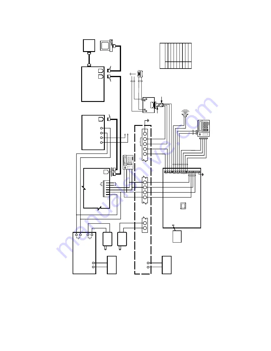
Symphony Symphony 8142 Installation And Setup Manual Download Page 66


SYM-SOC-V1

ADVANCED

USER

INTERFACE

GND

TO

 PANEL D

ATA

 OUT

TO

 PANEL D

ATA

 IN

+12VDC

RJ45

CONNECT

OR

RJ45

CONNECT

OR

RJ45

CONNECT

OR

STRAIGHT

-THR

OUGH

CABLE

PIN

1

2

3

4

5

6

7

8

ORN/WHT

ORN

GRN/WHT

BLU

BLU/WHT

GRN

BRN/WHT

BRN

COLOR

TIP

RING

TIP (GREEN)

RING (RED)


TIP (GREEN)

RING (RED)

TIP

TIP

RING

RING

TIP

RING

EAR

TH 

GR

OUND

RJ31X

JA

C

K

EAR

TH 

GR

OUND

SHOR

T PINS

T

O

 REST

ORE 

DEF

A

U

LT


SETTINGS

1

2

3

4

5

6

7

8

9

10

11

12

13

14

15

16

17

18

FR

OM

CONTR

OL

HOUSE

PHONES

AU

X

SPEAKER

KEYP

AD

A

UDIO

1

2

6

7

8

9

28

29

30

RJ-45

RJ-45

CABLE / DSL R

OUTER

WITH FIREW

ALL

LINKSYS BEFSR41

(OR EQ

UIV

A

LENT)

ADEMCO 12612

A

UX PWR SUPPL

Y

(12 VDC)

AC

IN

+

_

+

_

RED

BLACK

PWR SUPPL

Y

XFMR

16.5V

A

C

SYSTEM

XFMR

16.5V

A

C

AC

TELESMART

AUDIO B

US

TWISTED

PA

IR

RED

BLA

C

K

YELLO

W

GREEN

CA

T 5 (4 P

AIR)

(DIAL-UP CONNECTION)

CA

T 5 (4 P

AIR)

(BR

O

ADB

AND CONNECTION)

+12V

GND

P A

NEL

DA

T A

  IN

P A

NE

L

DA

T A

 OUT

KEYP

AD

(ECP)

D

ATA

 B

U

S

INCOMING

PHONE LINE

CA

T 5 CABLE CONNECTIONS

T

O

 RJ-45 CONNECT

OR

KEYP

ADS

YELLO

W

RED

BLA

C

K

GREEN

RJ-45

8950T

MODEM MODULE

PHONE

LINE

TR

+

_

12 VDC

IN

TELESMAR

T

81XX

DC

OUT

OR

(FOR NON-BR

O

ADBAND

INST

ALLA

TION ONL

Y)

CABLE

OR

DSL

MODEM

1361

1361

RJ-45

26

27

VIST

A-50PEN

+

_

RED

BLACK

PO

WER SUPPL

Y

BA

CKUP

BA

TTER

Y 12VDC

SYSTEM BA

CKUP

BA

TTER

Y

12VDC

T

O

 TELESMAR

MOD TERM.

 16

T

O

 TELESMAR

MOD TERM.

 15

COMPUTER

FOR BR

O

ADB

AND COMMUNICA

TION

FOR DIAL-UP COMMUNICA

TION

(BR

O

WN)

(GRA

Y)

620 DIRECT 

CONNECT

CORD

INCOMING

PHONE LINE

TO

PREMISES

PHONES

TIP (BR

O

WN)

RING (GRA

Y)

PLUG

ST

AND

ARD

KEYP

AD

(6160)

SPEAKER

(8 ohm)

A

UDIO B

U

S

(T

O A

UI and

T

eleSmar

t KEYP

ADS)

T

eleSMAR

T

KEYP

AD

(6162)

GRN (D

A

T

A IN)

RED (+12VDC)

BLA

CK (–)

YEL (D

A

T

A

 OUT)

1

OFF

4

MAX

7

INSTANT

READY

2

AWAY

5

TEST

8

CODE

0

3

STAY

6

BYPASS

9

CHIME

#

ARMED

READY

®

1

OFF

4

MAX

7

INSTANT

READY

2

AWAY

5

TEST

8

CODE

0

3

STAY

6

BYPASS

9

CHIME

#

ARMED

READY

MESSAGE


Summary of Contents for Symphony 8142

Page 1: ...6 6 P PS SK KR RQ Q G GY YD DQ QF FH HG G 8 8V VH HU U Q QW WH HU UI ID DF FH H QVWDOODWLRQ DQG 6HWXS XLGH K5762V2 5 01 ...

Page 2: ......

Page 3: ...r 4 3 Symphony ECP Addressing 4 4 How to Change the ECP Address 4 5 How to Enable Additional Symphony Units in the Control Panel 4 5 How to Access the Central Station Screen 4 9 How to Change the Address on Additional Symphony Units 10 How to Select System Options 4 11 How to Set the NIGHT Button Function 4 12 How to Setup Network Connectivity 4 13 About Using a PABX Line 4 16 How to Turn the PABX...

Page 4: ...erforming Diagnostics 7 3 LCD Display Test 7 3 Real Time Clock Test 7 5 Audio Test 7 6 LED Test 7 7 Keypad Test 7 8 Touch Screen Calibration 7 9 iCenter LED Operation 7 12 LEDs During Normal Idle State 7 12 LEDs During Software Downloading 7 13 LED Operation When Software Download Fails 7 13 Specifications 8 1 Specifications 8 1 Glossary 9 1 Glossary 9 1 ...

Page 5: ...tion Retrieval and recording of voice messages and Control of the home environment including the heating and air conditioning system lights garage door etc System Features Security Arm System Away Stay Night Disarm System User Codes Allows authorized user to add or delete codes Bypass Zones When system is not ready to arm displays any open zones with Zone number Zone description Status Bypass opti...

Page 6: ...essage Displays Date Time Sender Subject Voice Mail Message Displays Date Time Phone number Length of message Internet Accessibility Selections can be customized for each family member Typical selections include Message Display Event Reminders Appointments Shopping List Bills Due Favorite Web Sites ...

Page 7: ...ith the blade of a screwdriver while pulling the case back and case front apart 2 Locate the case back over the mounting surface such that the opening in the case back is aligned with the wire cable access opening in the mounting surface while passing the wires cable through the opening in the case back 3 Secure the case back to the mounting surface using four screws supplied Prior to attaching th...

Page 8: ... terminal pin 8 of the control panel to the Data Out terminal of Symphony green wire 3 Connect the terminal of the supplementary power supply to the 12VDC terminal of Symphony red wire 4 Connect the AUX terminal pin 7 to the terminal of the supplementary power supply black wire 5 Connect the terminal of the supplementary power supply to the GND terminal of Symphony black wire 6 Connect one end of ...

Page 9: ...als 28 TIP and 29 RING respectively 2 Connect the direct connect cord s brown and gray wires to TeleSMART s HOME PHONE terminals 15 and 16 respectively disconnecting them from the control s premises phone terminals if previously connected 3 Connect the control s local phone terminals 26 TIP and 27 RING to TeleSMART s PHONE LINE FROM CONTROL terminals 18 and 17 respectively using jumper wires not s...

Page 10: ...dresses in the control panel s Device Programming Mode before they will operate You can set TeleSMART keypads to addresses 02 22 25 30 addresses 00 01 23 and 24 are reserved Control Panel Connections TeleSMART is powered from the control s 12VDC keypad terminal Connect the control s keypad connection terminals to the TeleSMART Control terminals as shown in the System Interconnection Diagram in the...

Page 11: ...lthough Symphony provides its own security and does not require a firewall It is recommended that in most installations Symphony be connected through a Firewall Router device which will enable the device to be connected to the home network without altering the connections of any other device on the network Typical Residential Broadband Network Methods There are two typical broadband high data rate...

Page 12: ...e seamlessly delivered over the cable modem platform to end users A single downstream 6 MHz television channel may support up to 27 Mbps of downstream data throughput from the cable headend using 64 QAM quadrature amplitude modulation transmission technology Speeds can be boosted to 36 Mbps using 256 QAM Upstream channels may deliver 500 kbps to 10 Mbps from homes using 16QAM or QPSK quadrature ph...

Page 13: ...rate channels depending on the system ADSL modems provide data rates consistent with North American and European digital hierarchies and can be purchased with various speed ranges and capabilities The minimum configuration provides 1 5 or 2 0 Mbps downstream and a 16 kbps duplex channel others provide rates of 6 1 Mbps and 64 kbps duplex Products with downstream rates up to 8 Mbps and duplex rates...

Page 14: ...Symphony Installation and Setup Guide 3 4 ...

Page 15: ...er Up Symphony When initially powered the screen displays the boot sequence as it is performed After it is determined what services are available the screen displays the Touch Screen Calibration screen Calibrate the touch screen as follows ACTION SCREEN 1 Within the Touch Screen Calibration screen you are asked to Touch the center of the square displayed in the corner Press the center of the squar...

Page 16: ...e center of the square If touch screen calibration was successful CALIBRATION SUCCESSFUL is displayed momentarily You are then returned automatically to boot screen If touch screen calibration was not successful Calibration Unsuccessful is displayed momentarily You are then returned automatically to the first Touch Screen Calibration screen NOTE You will progress through the Touch Screen Calibrati...

Page 17: ...follows ACTION SCREEN 1 Press the box next to the Master Central Station ID The Enter Data keyboard is displayed 2 Press the Clear button to delete any previous account information typically set to FFFF from the manufacturer The text box at the top of the Enter Data keyboard is cleared with the cursor in the first position 3 Enter the 4 digit alphanumeric Master Central Station ID for this account...

Page 18: ...ess the OK button on the Set Account window You are then returned automatically to the boot screen Symphony ECP Addressing After the Account Number has been set the boot process will continue until the Set ECP Address window is displayed ACTION SCREEN If the system is incorporating only one Symphony leave the address set to 1 and press the OK button The boot up process will continue until completi...

Page 19: ... s Device Programming mode Device Address 1 is enabled by default Enable additional addresses using the unit set to address 1 How to Enable Additional Symphony Units in the Control Panel To enable a Symphony address in the control panel perform the following ACTION SCREEN 1 Press the SECURITY button on the Home screen The Arming screen is displayed 2 Press the MORE CHOICES button The More Choices ...

Page 20: ...Programming Mode by entering the 4 digit installer code 8 000 The Program Mode screen is displayed 5 Press 93 to display the ZONE PROG screen 6 Press 0 repeatedly until the DEVICE PROG screen is displayed 7 Press 1 to enter Device Programming The DEVICE ADDRESS screen is displayed ...

Page 21: ...o maximum number of partitions programmed for system in field 2 00 This is the primary partition for which the Symphony is intended to be used Enter 9 to make this Symphony a Master keypad for the system Press to accept entry The SOUND OPTION screen is displayed 11 Keypads can be individually programmed to suppress arm disarm beeps entry exit beeps and chime mode beeps This helps prevent unwanted ...

Page 22: ...ity to use this keypad for global arming disarming enter 0 Press to accept entry The AUI screen is displayed 13 Enter 1 YES to identify this device as an AUI Symphony The screen will prompt for the next Device Address to be programmed 14 Enter the next address to be programmed to enable another ECP device When Finished enter 00 then The QUIT MENU MODE screen is displayed 15 Enter 1 The Program Mod...

Page 23: ...ION SCREEN 1 Press the SECURITY button on the Home screen The Arming screen is displayed 2 Press the MORE CHOICES button The More Choices screen is displayed 3 Press the SETUP button on the More Choices screen The Setup screen is displayed 4 Press the ADVANCED SETUP button The Enter Authorized Code authorization screen is displayed ...

Page 24: ...ony one at a time and set its address to one of the addresses you enabled in the control panel If this is a first time power up of the unit follow the initialization procedure in Section 4 Otherwise follow the procedure below to change the address on the unit To change the address perform the following ACTION SCREEN 1 On the Central Station screen press the ECP Address button A pop up window is di...

Page 25: ...ns that can be added are MESSAGES VIDEO LIGHTING HEATING COOLING and INTERNET To avoid confusion to the user only buttons whose options are functional in the system should be displayed To select the system options do the following ACTION SCREEN 1 On the Central Station screen press the Options button A pop up window is displayed with options for selecting Messages Lighting and or Internet Select t...

Page 26: ...en selected arms perimeter zones without entry delay Maximum When selected arms all zones without entry delay To set the NIGHT button function do the following ACTION SCREEN 1 On the Central Station screen press the Night Setup button A Night Setup pop up window is displayed with options for selecting Away Stay Instant and Maximum Select the arming mode that will be activated by pressing the NIGHT...

Page 27: ...s defaulted to the Ethernet connection with DHCP also selected If you have selected another network connection option set the network connectivity as follows ACTION SCREEN 1 From the Home screen press the SECURITY button The Arming screen is displayed 2 Press the MORE CHOICES button The More Choices screen is displayed 3 Press the SETUP button The Setup screen is displayed ...

Page 28: ...r code The Advanced Setup menu screen is displayed 6 Press the Network Setup button The Network Setup screen is displayed 7 If you are using a dial up modem press the circle next to Dial up The Dial up screen is displayed with the previously ghosted Dial Up button now displayed and Use DHCP now ghosted If you are using Ethernet cable modem or DSL press the circle next to Ethernet ...

Page 29: ...ine go to step 10 If not perform step 12 Refer to the About Using a PABX Line paragraph below for important information 10 Press the Dial Up button The Dial Up Setup screen is displayed 11 Press the PPP Setup button The PPP Login Information screen is displayed Record the Phone Number displayed Press the box in which the phone number is displayed A data entry screen appears Enter 9 the recorded ph...

Page 30: ...rt system is connected to a PABX network e g Panasonic model 616 PABX system you must turn the PABX Line feature on in TeleSmart in order for the system to operate properly This option can only be programmed using a TeleSmart Touchpad 6139T How to Turn the PABX Line Feature On Off PROGRAM MODE 23 PBX LINE 1 Go to the PBX Line prompt option 23 2 To turn PBX Line on press 0 To turn PBX Line off pres...

Page 31: ...s blank Additionally you may enter the User Setup screen Advanced Setup screen or Clean Screen maintenance mode from the Setup screen by pressing the corresponding button Access the Setup screen as follows ACTION SCREEN 1 From the Home screen press the SECURITY button The Arming screen is displayed 2 Press the MORE CHOICES button The More Choices screen is displayed 3 Press the SETUP button on the...

Page 32: ...ide bar below the current contrast setting if another adjustment or selection is to be made go to the corresponding paragraph in this section If no additional adjustment or selection is to be made press the back icon at the upper right hand corner of the Setup screen to return to the previous screen or press the home icon in the upper left hand corner of the Setup screen to return to your home scr...

Page 33: ...press the slide bar below the current volume setting AUI 010 V1 VOLUME SLIDEBAR INDICATOR Volume Control How to Select Screen Saver Activation Time When Symphony is not armed and not active it will automatically go into screen saver mode display goes blank after the selected blank display time has expired unless you select never To select the time after which the screen will go blank do the follow...

Page 34: ...dvance to additional screens you can return to the Setup screen by pressing the Back icon as many times as required Should you then press either the Home or Back icon on the Setup screen the Settings Changed Pop up window is displayed and you can either save the new setting or not However if after selecting a new time setting you go to another screen or additional screens and then select the Home ...

Page 35: ...selected if it was not set at power up If Sync With Network Clock is NOT selected on the Set Time Date screen control panel time will be updated when Symphony time is set and you hit the OK button If Adjust for DST Daylight Savings Time is selected Symphony will adjust for Daylight Savings time When selected the next time the 1 hour timer expires the new value will be sent to the control panel IMP...

Page 36: ...Symphony Installation and Setup Guide 4 22 ...

Page 37: ...f the following systems Fire Burglary TeleSMART Internet Users for the systems are programmed in a central user setup location that provides the specific questions for the user pertaining to each system You may want these users to be the same but there are situations in which you may want a user to have access to one system e g TeleSMART without having access to another e g the Fire Burglary syste...

Page 38: ...reen is displayed 3 Press the SETUP button on the More Choices screen The Setup screen is displayed 4 Press the USER SETUP button on the Setup screen The User Setup screen is displayed How to Add a User Add a user as follows ACTION SCREEN Three selections are available add a user edit a user or delete a user ...

Page 39: ...ess the ADD USER button The User Authorization screen is displayed with the instructions Enter Authorized Code 2 Enter your Installer code The User Options screen is displayed 3 Press the box next to Enter User Name The Enter Data keyboard screen is displayed ...

Page 40: ...ayed Select the partitions and access level for this user If you are sending opening closing reports for this user enter the 3 digit User Number to identify the user If assigning this user to wireless key enter one of the zone numbers of the keyfob the wireless key must be programmed first before it can be assigned to a user NOTE The User Number and RF button zone fields will only be displayed whe...

Page 41: ...r is to have security access and TeleSMART access only press the SAVE button at this time If the user will also have Internet access go to step 8 8 Pres the WEB tab on the User Options screen The WEB access screen is displayed To provide this user with Internet access press the box next to Enable User for Web Access until a check appears You may also select the Auto Switch to WEB on Disarm option ...

Page 42: ...dit a user or delete a user 1 To delete a user touch the circle next to the user to be deleted and press the DELETE USER button The User Authorization screen is displayed with the instructions Enter Authorized Code 2 Enter your Installer code The Confirm Delete screen is displayed 3 Press the appropriate button The User Setup screen is displayed ...

Page 43: ...cle next to the user to be edited and press the EDIT USER button The User Authorization screen is displayed with the instructions Enter Authorized Code 2 Enter your Installer code The User Options screen is displayed 3 Select whatever options you wish to select for this user and press the Save button The configuration changes are saved and you are returned to the User Setup screen ...

Page 44: ...tion Users that are to have access only to the TeleSMART options no security or Internet options must be programmed here using the procedure described below To set or change a User Code ACTION SCREEN 1 From the Home screen press the MESSAGES button to display the TeleSMART main screen 2 Press the SETUP button The system enters the TeleSMART Setup screen 3 Press the Advanced Setup button The Advanc...

Page 45: ...ith Code To Change User Settings 5 Enter your 4 digit Installer Code The User Authorization screen is displayed with the instructions Enter User you wish to Edit 6 Enter the single digit user number The User Settings screen is displayed 7 Select options and press the Save Settings button The code is saved and The Advanced Setup screen is displayed ...

Page 46: ...Symphony Installation and Setup Guide 5 10 ...

Page 47: ...mphony is maintenance free How to Clean Symphony IMPORTANT Do not use an abrasive cleaning agent or abrasive cloth when cleaning Symphony or damage to the touch screen may occur Clean Symphony as follows ACTION SCREEN 1 From the Home screen press the SECURITY button The Arming screen is displayed 2 Press the MORE CHOICES button The More Choices screen is displayed ...

Page 48: ...oft cloth When the counter reaches zero the window automatically closes and the touch screen is active NOTE Do not spray cleaning agent directly on the screen spray it on cloth then wipe surface area Routine Care Treat the components of the security system as you would any other electrical equipment Do not slam sensor protected doors or windows Keep dust from accumulating on the keypad and all pro...

Page 49: ...n tests is provided that allows verification of correct operation of Symphony and its connections to the security system and the Internet There are a total of six diagnostic tests and one calibration procedure How to Access the Diagnostics To access diagnostics do the following ACTION SCREEN 1 From the Home screen press the SECURITY button The Arming screen is displayed 2 From the Arming screen pr...

Page 50: ...screen is displayed 4 Press the Advanced Setup button on the Setup screen The Enter Authorized Code authorization screen is displayed 5 Enter your 4 digit Installer code The Advanced Setup menu screen is displayed 5 Press the Diagnostics button on the Advanced Setup menu screen The Diagnostics Test screen is displayed ...

Page 51: ...r of the Diagnostics Tests screen to return to your home page Once the Diagnostics Tests screen is exited subsequent entry to this screen displays all test options as Not Performed LCD Display Test Perform the LCD Display Test as follows ACTION SCREEN 1 When you press the Test button associated with the LCD Display Test a pop up Confirmation Window is displayed in the center of the screen with an ...

Page 52: ...y the Color Bar Pop Up Confirmation Window is displayed in the center of the screen as shown below Within the Confirmation Window the question Do you see Color Bars Blk R G LGr B M Y W is displayed 5 When you press the Yes or No button accordingly automatically the contrast test begins from low to high Changing Contrast is displayed in the center of the screen during this time At the conclusion of...

Page 53: ...on of this test when the system is returned to the Diagnostics Tests screen Failed is displayed in test status column Real Time Clock Test Perform the Real Time Clock Test as follows ACTION SCREEN When you press the Test button associated with the Real Time Clock Test Testing is displayed in the test status column on the Diagnostics Tests screen At the conclusion of the test either a green Passed ...

Page 54: ...und from the speaker At the conclusion of the test a pop up Confirmation Window is displayed in the center of the Diagnostics Tests screen Within the Confirmation Window the question Did you hear 4 Beeps is displayed When you press the Yes button a green Passed indication is displayed in the test status column on the Diagnostics Tests screen When you press the No button a red Failed indication is ...

Page 55: ...amber red green green 5 times At the conclusion of the test a pop up Confirmation Window is displayed in the center of the Diagnostics Tests screen 2 Within the Confirmation Window the question Did you see chasing LED pattern is displayed If you press the Yes button a green Passed indication is displayed in the test status column on the Diagnostics Tests screen If you press the No button a red Fai...

Page 56: ...lf Test screen NOTE Pressing the Cancel button at any time even if several keys have been pressed returns the system to the Diagnostics Tests screen If the keypad is functioning correctly and the keys were pressed in the order above a green Passed message is displayed in the center of the Keypad Self Test screen The system then automatically returns to the Diagnostics Tests screen If the keypad is...

Page 57: ...the SECURITY button The Arming screen is displayed 2 From the Arming screen press the MORE CHOICES button The More Choices screen is displayed 3 Press the SETUP button on the More Choices screen The Setup screen is displayed 4 Press the Advanced Setup button on the Setup screen The Enter Authorized Code authorization screen is displayed ...

Page 58: ...egin the Touch Screen calibration from the Diagnostics Tests screen by pressing the Calibrate button When the Calibrate button is pressed the Touch Screen Calibration screen is displayed Within the Touch Screen Calibration screen you are asked to Touch the center of the square displayed in the corner Press the center of the square When this square is touched the Touch Screen Calibration screen dis...

Page 59: ...nter of the Touch Screen Calibration screen 9 Press the center of the square If touch screen calibration was successful CALIBRATION SUCCESSFUL is displayed momentarily You are then returned automatically to the Diagnostics Tests screen If touch screen calibration was not successful Calibration Unsuccessful is displayed momentarily You are then returned automatically to the first Touch Screen Calib...

Page 60: ...al idle Software download Software download Failure Modes Each LED can have four different status indications ON OFF FAST BLINK and SLOW BLINK All LEDs do not use all of the above states Details are provided below LEDs During Normal Idle State LED DESCRIPTION WEB ON Connected to Internet OFF Not connected FAST BLINK Either sending or receiving data SLOW BLINK Connecting to server BB or dialing to ...

Page 61: ...onfiguration data or if with ARMED FAST BLINK then it connected to server but failed authentication MESSAGE ON Erasing application code SLOW BLINK Downloading application code VERY SLOW BLINK Verifying CRC after successful code download LED Operation When Software Download Fails There are the following sequences providing the extra failure information 1 CRC failure 1 calculated CRC does not match ...

Page 62: ...Symphony Installation and Setup Guide 7 14 ...

Page 63: ...ns MECHANICAL Dimensions Width 7 inches Height 8 inches Depth 1 inches ELECTRICAL Operating Voltage Current Drain Standby LCD off Sound off Active LCD on Sound off Alarm LCD off Sound on Alarm LCD on Sound on 150mA 350mA 200mA maximum 400mA maximum ...

Page 64: ...Symphony Installation and Setup Guide 8 2 ...

Page 65: ...er consisting of 4 parts separated by periods sometimes called a dotted quad for example 204 17 29 11 assigned to every computer workstation connected to the Internet IP numbers can be static assigned and unchanging or dynamic assigned via DHCP at each and every startup ISP Internet Service Provider LAN Local Area Network MAC Address The hardware address of a device connected to a network NAT Netw...

Page 66: ...AT 5 4 PAIR BROADBAND CONNECTION 12V GND PANEL DATA IN PANEL DATA OUT KEYPAD ECP DATA BUS INCOMING PHONE LINE CAT 5 CABLE CONNECTIONS TO RJ 45 CONNECTOR KEYPADS YELLOW RED BLACK GREEN RJ 45 8950T MODEM MODULE PHONE LINE T R _ 12 VDC IN TELESMART 81XX DC OUT OR FOR NON BROADBAND INSTALLATION ONLY CABLE OR DSL MODEM 1361 1361 RJ 45 26 27 VISTA 50PEN _ RED BLACK POWER SUPPLY BACKUP BATTERY 12VDC SYST...

Page 67: ...Y POWER SUPPLY TELESMART AUDIO BUS GND DATA OUT DATA IN 12VDC BLACK RED BLACK GREEN YELLOW RJ45 10BASE T ETHERNET CONNECTOR TO ETHERNET HUB _ _ AUX SPRING CLIP ON BOTTOM PIN 1 AUX DATA IN DATA OUT 6 7 8 9 STRAIGHT THROUGH CABLE PIN 1 2 3 4 5 6 7 8 ORN WHT ORN GRN WHT BLU BLU WHT GRN BRN WHT BRN COLOR ...

Page 68: ...FOR ANY CONSEQUENTIAL OR INCIDENTAL DAMAGES FOR BREACH OF THIS OR ANY OTHER WARRANTY EXPRESS OR IMPLIED OR UPON ANY OTHER BASIS OF LIABILITY WHATSOEVER EVEN IF THE LOSS OR DAMAGE IS CAUSED BY THE SELLER S OWN NEGLIGENCE OR FAULT Seller does not represent that the products it sells may not be compromised or circumvented that the products will prevent any personal injury or property loss by burglary...

Reviews: