74
08/2009 Rev. 0.4
S1000 All in One
S3000 All in One (MAXI)
S1000 / S3000 / S3000 MAXI
08/2009 Rev. 0.4
75
S1000 All in One
S3000 All in One (MAXI)
S1000 / S3000 / S3000 MAXI
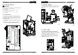
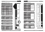
5.2 Main circuit board entrances
Connector J12
Connector cable between the main circuit and door circuit
Connector J7
Pin
Sensor
Colour
Comments
1-2
-
3
Drip tray sensor
Yellow
4
Drip tray sensor Mass
Black
5
Level sensor Low
Brown
6
Level sensor Mass
Green
7
Level sensor High
White
8-13
Not used
-
14
Waste bin switch
Grey
Ingr. motor in position;
contact closed
15
Brewer switch
Pink
Ingr. motor in position;
contact closed
16
Door switch
Orange
Ingr. motor in position;
contact closed
17-18
Not used
-
Connector J16
Pin
Sensor
Colour
Comments
1
NTC sensor
Violet
2
NTC sensor
Violet
Battery
Lithium 3V Type CR2025
Art. No. 02816
Fuse
6,3A slow
Art. No. 03391
Connector J1
Pin
Colour
Comments
1
Mass (GND)
Black
2
Mass (GND)
Black
3
+24V DC
Red
4
+24V DC
Red
2
1
TEMP1
2
1
4
3
24V DC
KEY
/ DISPLA
Y
INPUTS
J12
J7
J16
J1
F1
+
BATT
F6,3AT
1
2
3
4
5
6
7
8
9
10
11
12
18
17
16
15
14
13
12
11
10
9
8
7
6
5
4
3
2
1
SENSORS
+5V
LB
LSL
GND
AS
BS
DS
LSH
GND
GND
GND
Fig. 17
5.3 Main circuit board exits
Connector J2
Pin
Motor
Colour
Comments
17-18
Mixer 1
Black
Take care to rotate in
the right direction!
24 DC (red wire)
on red spot on Mixer and
Ingredients Motor.
15-16
Mixer 2
Violet
13-14
Mixer 3
Pink
11-12
Ingredient Motor 1
Brown
9-10
Not used
-
7-8
Ingredient Motor 3
White
5-6
Not used
-
3-4
Ingredient Motor 5
Grey
1-2
Not used
-
Connector J4
Pin
Valve
Colour
Comments
17-18
KW 1 (inlet valve)
Violet
Red wire is a shared
(24VDC) connection
15-16
KW 2
-
13-14
KW 3
-
11-12
DV 1 (mixer 1 valve)
Brown
9-10
DV 2 (mixer 2 valve)
White
7-8
DV 3 (mixer 3 valve)
Green
5-6
DV 4 (hot water tap)
Yellow
3-4
Not used
-
1-2
Not used
-
Connector J15
Pin
Motor
Colour
Comments
2
Ventilator
Red
1
Orange
Connector J6
Pin
Relay
Colour
Comments
4
Power relay (element)
Red
3
White
2
Power relay
-
-
1
18
17
16
15
14
13
12
11
10
9
8
7
6
5
4
3
2
1
MIX/BR
MIX2
MIX3
IM1
IM2
IM3
IM4
IM5
IM6
2
1
KW1
KW2
KW3
DV1
DV2
DV3
DV4
DV5
DV6
18
17
16
15
14
13
12
11
10
9
8
7
6
5
4
3
2
1
2
1
HEA
T
ER
RELAIS
DOSING V
A
LVES
V
A
LVES
INGREDIENT
MOT
O
RS
MIXERS
4
3
FA
N
INLET
OUTPUTS
J15
J6
J2
J4
H1
H2/3
Fig. 18


