background image

15

Q u i c k   R e f e r e n c e

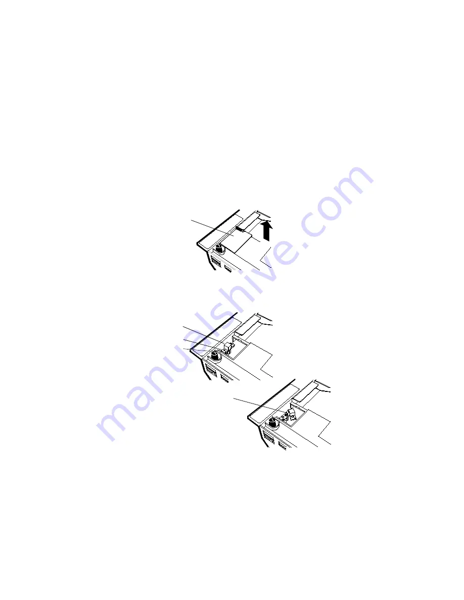
Access the Calibration Switch

The Calibration Switch is located below the Top Plate. Remove the 
Top Plate to access to the Calibration Switch cover. Lift the cover up 
to remove.

Remove the screw that secures the Calibration Switch cover. Also 
remove the seal if one is present. Rotate the Calibration Switch 
cover to access to the Calibration Switch.

Calibration

Switch Cover

Calibration Switch

Security Cover

Screw

Wire Seal

Calibration

Switch

Summary of Contents for QRG 7875

Page 1: ...7 8 7 5 S c a n n e r S c a l e ...

Page 2: ...mplication estoppel or otherwise under any patent right or patent covering or relating to any combination system apparatus machine material method or process in which Symbol products might be used An implied license only exists for equipment circuits and subsystems contained in Symbol products Symbol is a registered trademark of Symbol Technologies Inc Other product names mentioned in this manual ...

Page 3: ... Wiring Cable Hole Requirements 2 Connect the Cables see page 7 Power Supply Remote Display Interface Cables RS 232 Peripheral Cable 3 Install 7875 in Checkstand see page 10 Set Communications Protocol Switch Put the 7875 in Checkstand Cutout Align the 7875 to the Checkstand 4 Calibrate the Scale see page 13 Access Calibration Switch Exercise the Scale Perform Calibration Validate the Calibration ...

Page 4: ...m 50 95 cm 3 49 cm 1 27 cm 43 97 cm 12 1 16 in 20 1 16 in 1 3 8 in 1 2 in 17 5 16 in F G H I 7875 1000 Scanner 3 49 cm 13 0 cm 18 10 cm 18 42 cm 1 3 8 in 5 1 8 in 7 1 8 in 7 1 4 in 7875 2000 Scanner Scale 3 49 cm 13 0 cm 17 78 cm 18 42 cm 1 3 8 in 5 1 8 in 7 in 7 1 4 in No electronics under 7875 F G F A C C B D D E H I A B E C C D Recommended shelf to catch the 7875 if dropped during installation ...

Page 5: ...heckstand Cutout 7875 3000 Note The 7875 3000 must sit on a shelf below the checkstand surface The shelf should be open at the front and back A B C D 29 51 cm 40 96 cm 3 49 cm 0 95 cm 11 5 8 in 16 1 8 in 1 3 8 in 3 8 in E F G H 37 34 cm 12 54 cm 18 10 cm 18 42 cm 14 3 4 in 4 15 16 in 7 1 8 in 7 1 4 in F A C B D E G H A B C D No electronics under NCR 7875 ...

Page 6: ...nd structure is not removable for servicing 7 0 in 17 8 cm minimum if checkstand structure is re movable for servicing C 5 1in 13 0 cm minimum clearance to closest checkstand panel The 7875 must not be supported by this panel 30 50 60 60 This area must be clear for viewing optional integrated display B C A A Mounting surface for keyboard must be removable for servicing and vertical window replacem...

Page 7: ...han 12 6 F 7 C above the ambient temperature outside the checkstand For example if the ambient temperature outside the checkstand is 76 F 24 4 C the ambient temperature inside the checkstand cannot be greater than 88 6 F 31 4 C If the checkstand contains other heat producing equipment you may need to use forced air to keep the temperature within the specified range However air coming into or leavi...

Page 8: ... Motor Belt Control Lighting Misc equip Isolated Insulated Ground Bus Distribution Panel Neutral Bus Circuit B Terminal Circuit C Scanner Scale Receptacle should be easily assessible and near the Scanner Scale Isolated Ground Receptacles Checkstand Frame Note The electrical wiring must meet all electrical codes laws and regulations Feeder wiring and insulated ground from main service panel to dist...

Page 9: ...he following table gives the minimum hole size for each of the 7875 cables Connect the Cables There are several cables associated with the 7875 some required with every installation and some optional depending on the system Make sure you have all the necessary cables for your installation Connect the cables according to one of the following two illustrations Cable Cable Length Minimum Hole Size Po...

Page 10: ...Cable Installation DC POWER REMOTE DISPLAY 5A MAX SCANNER Check switch settings 5V PORT 1 PORT 2 DUAL PERIPHERAL PORTS AC Power Cord Power Supply DC Power Cable Interface Cable Host Terminal 7875 Scanner Scale RS 232 Peripheral Remote Display ...

Page 11: ... REMOTE DISPLAY 5A MAX SCANNER AUX PORT DATA CHKR Check switch settings 5V PORT 1 PORT 2 DUAL PERIPHERAL PORTS AC Power Cord Power Supply DC Power Cable Scale Interface Cable Host Terminal 7875 Scanner Scale RS 232 Peripheral Remote Display Scanner Interface Cable ...

Page 12: ...ches 1 meter long with 8 pin phone type connectors on each end Install 7875 in Checkstand Set the Communications Protocol Switch Before setting the 7875 into the cutout in the checkstand verify that the Communications Protocol Switch is properly set Single cable units have one switch dual cable units have two The switches are located on the Interface Board and you can access them through holes in ...

Page 13: ...eckstand cutout Be careful not to damage any of the cables After the unit is properly sitting on its supports install the Top Plate Note It is important that the 7875 does not rock on its sup ports Make sure all adjustable supports are securely fastened and that the 7875 is sitting on all supports AUX PORT DATACHKR SCANNER DATACHKR OCIA IBM RS 232 RS 232 Make sure power is off before changing swit...

Page 14: ... top of the checkstand Note The four adjustable support posts on the Scale Hinge Assembly are set at the factory Do not attempt to adjust the Top Plate using these posts Adjust the 7875 sup ports to align the Top Plate with the checkstand If the Top Plate is properly aligned with the checkstand an item should easily slide from the checkstand onto the Top Plate and then from the Top Plate onto the ...

Page 15: ...ction Also you MUST calibrate the scale when you install an 7875 Scanner Scale Note Your 7875 Scanner Scale may not have an integrated display and may not have a remote display when con nected to some host terminals If this is the case a Field Correct Alignment Bad Alignment Scanner Too High Bad Alignment Scanner Too Low High Surface Low Surface High Surface Low Surface ...

Page 16: ...oard maintains an audit trail of scale calibration and programming activity The audit trail contains an event counter that records the number of times the scale has been calibrated You can display the audit trail count on an integrated remote or Field Service Calibration Display by pressing the Scale Zero Button on the Operator Display Panel The display alternates between Cal xxx and PAr xxx Exerc...

Page 17: ...e to access to the Calibration Switch cover Lift the cover up to remove Remove the screw that secures the Calibration Switch cover Also remove the seal if one is present Rotate the Calibration Switch cover to access to the Calibration Switch Calibration Switch Cover Calibration Switch Security Cover Screw Wire Seal Calibration Switch ...

Page 18: ...s government requirements of testing the accuracy of the scale after performing a scale calibration It contains a series of four tests that must be run in the continuous sequence given Increasing Load Test This test checks the scale s accuracy when incrementally adding weight to the center of the top plate Use weights that correspond to the 7875 weight feature Display Add Weight Remove Weight Read...

Page 19: ... 7875 weight feature The display shows a series of dashes to indicate an over capacity condition 2 9 995 kg 2 5 kg 0 1 kg 2 5 0 00 kg 13 995 kg 2 5 kg 0 1 kg 2 5 0 00 kg 30 0 lb 5 0 lb 0 2 lb 5 0 0 00 lb 3 9 995 kg 2 5 kg 5 0 0 005 kg 13 995 kg 4 5 kg 7 0 0 005 kg 30 0 lb 5 0 lb 10 0 0 01 lb 4 9 995 kg 2 5 kg 7 5 0 005 kg 13 995 kg 3 0 kg 10 0 0 005 kg 30 0 lb 10 0 lb 20 0 0 01 lb 5 9 995 kg 2 495...

Page 20: ...kg 0 04 kg 9 995 0 005 kg 13 995 kg 0 04 kg 13 995 0 005 kg 30 0 lb 0 08 lb 30 0 0 01 lb Step Weight Feature Add Weight Remove Weight Display Result 1 9 995 kg 2 495 kg 7 5 0 005 kg 13 995 kg 3 995 kg 10 0 0 005 kg 30 0 lb 10 0 lb 20 0 0 01 lb 2 9 995 kg 5 0 kg 2 5 0 00 kg 13 995 kg 7 5 kg 2 5 0 00 kg 30 0 lb 15 0 lb 5 0 0 00 lb 3 9 995 kg 0 1 kg 2 5 kg 0 1 0 00 kg 13 995 kg 0 1 kg 2 5 kg 0 1 0 00...

Page 21: ...ht in position 1 on the Top Plate 2 Move the weight to position 2 on the Top Plate The display should show 5 00 0 005 kg 15 00 0 01 lb 3 Repeat step 2 for positions 3 4 and 5 4 Move the weight to position 1 again 5 Remove all weights The display should read 0 000 0 000kg 0 00 0 00 lb 6 Raise and hold up the Top Plate Record the Cal and PAr val ues shown on the display 1 2 3 4 5 ...

Page 22: ...an On Off switch Use the circuit breaker switch in the checkstand to turn the unit on or off Setting the Program Parameters Caution Some host terminals can corrupt the 7875 program if they are running and are connected to the 7875 while you are making program changes Either turn off the host terminal or disconnect the interface cable before scanning any programming tags To make changes to the prog...

Page 23: ...its parameter data by scanning the appropriate Hex tags 3 Save the program by scanning the Save and Reset tag Note In most cases the factory determined defaults are the correct parameter setting However if you do need to make changes first set all parameters to default values then make any necessary changes to the appropriate pa rameters Scan Sample Tags Scan some sample tags to verify that the 78...

Page 24: ...22 7 8 7 5 S c a n n e r S c a l e 1 77062 37920 4 1 7 7 0 6 2 3 7 9 2 0 1 7 7 0 6 2 3 7 9 2 0 0 1 7 7 0 6 2 3 7 9 2 0 UPC A Code 39 Code 128 Interleaved 2 of 5 ...

Page 25: ...onents The7875 does not have a power switch Turn it on and off using the circuit breaker switch located in the checkstand that supplies power to the unit Be sure this switch is in the On position The Status Indicator on the Operator Display Panel is red when the 7875 is ready To scan slide an item from the checkstand across the scanner and back onto the checkstand With a good scan the Status Indic...

Page 26: ...cale displays all zeros If not press the Scale Zero Button Note Place the item you are weighing in the center of the Top Plate The item must fit completely on the Top Plate and not hang over onto the checkstand When the scale weighs an item the Status Indicator flashes green and a good weigh tone sounds Nothing happens if the scale cannot weigh an item Status Indicator Scale Zero Button Top Plate ...

Page 27: ... Clean Window indicator flashes when the scan windows need cleaning Use a soft cloth moistened with a common non abrasive liquid window cleaner to clean the scan windows Be sure to spray the cleaner onto the cloth not directly onto the 7875 Note Scale problems can occur from debris collecting under the Top Plate Be sure to keep the plastic subplate clean to prevent interference with the Top Plate ...

Page 28: ...Off Communi cations is IBM 468x and scan ner is off line Verify that the IBM termi nal is turned on Verify that the IBM termi nal is recognizing the 7875 Verify that the Interface Cable is properly connect ed Scanner does not read tags Red Flash ing Off Internal failure Remove power from the 7875 and then supply power again If the prob lem is not corrected have scanner repaired Scanner reads only ...

Page 29: ...ve unit repaired Error code 4 displays Possible scale error Press Scale Zero button and retry If error code persists have unit re paired Error code 4 displays Slight vibration to scale when calibrat ing Calibrate scale not permitting any external scale movement while the weights are on the scale Scale display is blank Top Plate is being prevented from moving down Remove interference around edge of...

Page 30: ...ree beeps If the 7875 has the Voice feature enabled the communications protocol is given audibly If the Voice feature is not enabled the Status indicator flashes green and the 7875 beeps identi fying the communication protocol Following are the number of beeps that sound for each communication protocol 3 Remove power from the 7875 Beeper Indications Beep Sequence Indication 1 Short high pitched be...

Page 31: ...anning the Hex B tag Each time you scan the Hex B tag the tone frequency increases one unit Scan the End tag or a valid Hex tag to end this mode Tone Length Milliseconds C When entering Tone Length the adjustment can be incremented upward by scanning the Hex C tag Each time you scan the Hex C tag the tone length increases one unit Scan the End tag ora valid Hex tag to end this mode Tone Volume D W...

Page 32: ...ameter to 0 Leaving the laser light on all the time reduces its life expectancy 1 2 TIMERS A B C D E UPC EAN 0 1 Disable Enable Version D 0 1 None D 1 2 3 D 2 D 3 4 5 D 4 D 5 Extend UPC A To EAN 13 0 1 Disable Enable Extend UPC E To UPC A 0 1 Disable Enable Periodical Codes 0 1 Disable Enable Periodical Code Extension 0 1 2 Digit Only 5 Digit Only 2 2 Digit 5 Digit Send Data 0 1 Data As Decoded Pe...

Page 33: ...k Digit 0 1 Disable Enable Allow One Character Tags 0 1 Disable Enable 1 5 INTERLEAVED 2 OF 5 A B C D Interleaved 2 of 5 0 1 Disable Enable Bar Code Length 0 1 Range Check Specific Check Value 1 Characters Minimum 0 5 0 9 Character 1 Character 2 0 8 Default Value 2 Characters Minimum 0 5 0 9 Character 1 Character 2 1 6 Default Check Digit Present 0 1 Disable Enable Transmit Check Digit 0 1 Disable...

Page 34: ...ommon Byte 1 0 7 Hex Character 0 F Hex Character 5 D Default Common Byte 2 0 7 Hex Character 0 F Hex Character Default 4 2 Bar Code Type 0 1 2 3 4 5 6 7 UPC A UPC D UPC E EAN 8 EAN 13 Code 39 Code 128 Interleaved 2 of 5 Common Byte 0 1 2 3 None Common Byte 1 Common Byte 2 Both Common Bytes Unique Identifier 0 7 Hex Character 0 F Hex Character Default Varies according to Bar Code Type Version Numbe...

Page 35: ...r CTS 3 4 5 RTS High Wait for CTS Note Parity must be Odd or Even on a 7870 7875 Odd is used if None is selected 2 1 RS 232 PARAMETERS SET 2 A B C BCC Options 0 Disable 1 Enable Default 7870 7875 1000 Disable 7870 7875 2000 Enable Interface Control 0 None 1 ACK NAK 2 XOn XOff 3 ACK NAK XOn XOff Check Digit 0 Disable UPC A Disable EAN 8 Disable EAN 13 Disable UPC E 1 Enable UPC A Enable EAN 8 Enabl...

Page 36: ... BYTE A B Terminator Byte 0 Disable 1 Enable ASCII Code 0 7 Hex Character ASCII Code Chart 0 F Hex Character ASCII Code Chart 0 3 Default Note A Terminator Byte is required on a 7870 7875 If you select Disable it is ignored and an ETX 03 is sent 2 4 RS 232 COMMUNICATIONS OPTIONS Message Delay 0 No Delay 1 10ms Delay 2 50ms Delay Scanner or Scanner Scale Format 4 Scanner Only 5 Scanner Scale Normal...

Page 37: ...oggle On and Off 3 2 MISCELLANEOUS PARAMETERS 5 Second Weight Display Timer 1 Disable 2 Enable IBM Tone Control Good Read Tone Control 3 Disable 4 Enable 5 Disable 6 Enable OCIA Price Display IBM Rexmit Control 7 3 Times 8 Forever OCIA Blank Display in Price Mode 9 Disable A Enable Enable Disable Voice Messages D Toggle Default Enabled IBM Tag Data Format E Hex F ASCII ...

Page 38: ...a b c d e f g h i j k l m n o 50 51 52 53 54 55 56 57 58 59 5A 5B 5C 5D 5E 5F P Q R S T U V W X Y Z _ 40 41 42 43 44 45 46 47 48 49 4A 4B 4C 4D 4E 4F A B C D E F G H I J K L M N O 30 31 32 33 34 35 36 37 38 39 3A 3B 3C 3D 3E 3F 0 1 2 3 4 6 5 7 8 9 20 21 22 23 24 25 26 27 28 29 2A 2B 2C 2D 2E 2F SP 10 11 12 13 14 15 16 17 18 19 1A 1B 1C 1D 1E 1F DLE DC1 DC2 DC3 DC4 NAK SYN ETB CAN EM SUB ESC FS GS ...

Page 39: ...urning the equipment off and on the user is encouraged to try to correct the interference by one or more of the following measures Re orient or relocate the receiving antenna Increase the separation between the equipment and receiver Connect the equipment into an outlet on a circuit different from that which the receiver is connected Consult the dealer or an experienced radio TV technician for hel...

Page 40: ...ischarge immunity test IEC 1000 4 3 1995 03 Electromagnetic compatibility EMC Part 4 Testing and measurement techniques Section 3 Radiated radio frequency electromag netic field immunity test EN 60 950 Amd 1 Amd 2 Safety of Information Technology Equipment Including Electrical Business Equipment EN 60 825 1 EN 60 825 Safety of Devices Containing Lasers Laser Devices Symbol products using lasers co...

Page 41: ...ect Laser Light Appareil à Laser de classe IIa Eviter Toute Exposition Prolongèe de la vue à la lumiè re laser directe Class IIa Producto Laser Tratè De no ver directamente èl Rayo Laser por mucho tiempò IEC CLASS 1 LASER PRODUCT C This laser module does not comply with 21CFR1040 Use only as a component ...

Page 42: ...EN KLASSE 2 LASERLYS IKKE STIRR INN I LYSSTRÅLEN KLASSE 2 LASERPRODUKT LASERPRODUKT KLASSE 2 FINNISH PORTUGUESE LUOKKA 1 LUOKKA 1 LASERTUOTE CLASSE 1 PRODUTO LASER DA CLASSE 1 LUOKKA 2 LASERVALO ÄLÄ TUIJOTA SÄDETTÄ CLASSE 2 LUZ DE LASER NÃO FIXAR O RAIO LUMINOSO LUOKKA 2 LASERTUOTE PRODUTO LASER DA CLASSE 2 FRENCH SPANISH CLASSE 1 PRODUIT LASER DE CLASSE 1 CLASE 1 PRODUCTO LASER DE LA CLASE 1 CLAS...

Page 43: ... accordance with any operating or handling instructions supplied by Symbol iii which has been subjected to unusual physical or electrical stress misuse abuse power shortage negligence or accident or iv which has been used other than in accordance with the product operating and handling instructions Preventive maintenance is the responsibility of customer and is not covered under this warranty Wear...

Page 44: ...rges will be in accordance with Symbol s Exchange Policy in effect at the time of the exchange Customer accepts full responsibility for its software and data including the appropriate backup thereof Repair or replacement of a product during warranty will not extend the original warranty term Symbol s Customer Service organization offers an array of service plans such as on site depot or phone supp...

Reviews: