background image

6. CYLINDER HEAD/VALVE 


6-10 


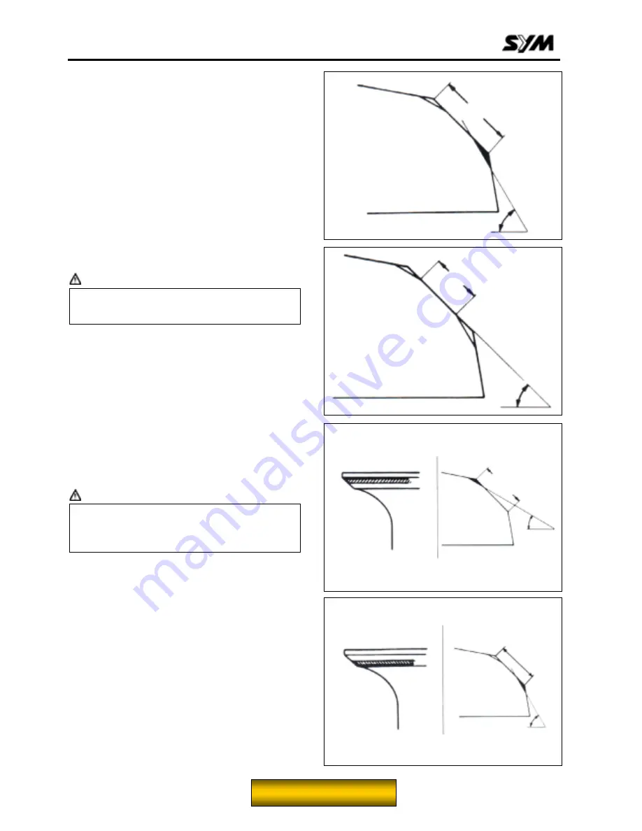
Use 60° cutter to cut a quarter lower part out. 
Remove the cutter and check new valve seat. 


Use 45° cutter to grind the valve seat to specified 
width. 


Caution


Grind valve seat again if necessary. 


Coat the valve seat surface with red paint. 
Install the valve through valve guide until the 
valve contacting with valve seat, slightly press 
down the valve but do not rotate it so that a seal 
track will be created on contact surface. 


Caution


If the contact surface too high, grind the valve 
seat with 32° cutter. 
Then, grind the valve seat to specified width. 
 
If the contact surface too low, grind the valve 
seat with 60° cutter. 
Then, grind the valve seat to specified width. 


z

Make sure that all roughness and uneven 
faces had been ground. 

z

The contact surfaces of valve and valve 
seat are very important to the valve 
sealing capacity. 

Old valve seat width 

60° 

45° 

1.0mm (0.04 in) 


Contact surface too 
high 

Contact surface too 
low 

32° 

60° 

Old valve seat width 

Old valve seat width 

To this chapter contents 

Summary of Contents for JOYRIDE 100

Page 1: ...SERVICE MANUAL FORWARD HOW TO USE THIS MANUAL CONTENTS...

Page 2: ...ervice Procedures Operation Key Points and Inspection Adjustment so that provides technician with service guidelines If the style and construction of the motorcycle JOYRIDE 125 150 200 are different f...

Page 3: ...the parts set of assembly body The fifteenth chapter is electrical equipment The sixteenth chapter is emission control system The seventeenth chapter is wiring diagram Please see index of content for...

Page 4: ...V BELT DRIVING SYSTEM FOOT STARTER 8 9 1 9 8 FINAL DRIVING MECHANISM 9 10 1 10 6 ALTERNATOR STARTING CLUTCH 10 11 1 11 8 CRANKSHAFT CRANKCASE 11 12 1 12 11 COOLING SYSTEM 12 13 1 13 13 BODY COVERS 13...

Page 5: ...beam Passing Turn signal Horn switch Muffler Reserved tank cap Coolant filler cap Ignition Seat open switch Fuses C D I Gear oil drain plug REG REC Start MAG switch Battery IG coil Horn Fuel tank Fue...

Page 6: ...0 JASO FC class oil Warranty will not cover the damage that caused by not apply with the limited engine oil Recommended oil MAX 2 serial oils Grease King Mate G 3 is recommended Gear oil King Mate gea...

Page 7: ...in flush it off immediately with water If you get battery acid in your eyes flush it off immediately with water and then go to hospital to see an ophthalmologist If you swallow it by mistake drink a l...

Page 8: ...z Never bend or twist a control cable to prevent unsmooth control and premature worn out z Rubber parts may become deteriorated when old and prone to be damaged by solvent and oil Check these parts be...

Page 9: ...ing outside check the shaft on which the oil seal is to be installed for smoothness and for burrs that may damage the oil seal z Remove residues of the old gasket or sealant before reinstallation grin...

Page 10: ...ch 3 piece centrifugal dry type Position and arrangement Horizontal below center CYL incline 80 PERFORMANCE Transmission C V T Fuel Used 92 Unleaded gasoline Speed meter 0 140 km hr Cycle Cooling 4 st...

Page 11: ...utch 3 piece centrifugal dry type Position and arrangement Horizontal below center CYL incline 80 PERFORMANCE Transmission C V T Fuel Used 92 Unleaded gasoline Speed meter 0 140 km hr Cycle Cooling 4...

Page 12: ...ch 3 piece centrifugal dry type Position and arrangement Horizontal below center CYL incline 80 PERFORMANCE Transmission C V T Fuel Used 92 Unleaded gasoline Speed meter 0 140 km hr Cycle Cooling 4 st...

Page 13: ...ket 1 8 1 8 2 2 Nut for engine hanger bracket 1 10 4 0 5 0 Bolt for engine hanger bracket 1 10 4 0 5 0 Engine mounting bolt 1 10 3 5 4 5 Front wheel shaft nut 1 12 5 0 7 0 Rear wheel shaft nut 1 14 11...

Page 14: ...5 mm Bolt Nut 0 45 0 6 6 mm Bolt Nut 0 8 1 2 8 mm Bolt Nut 1 8 2 5 10 mm Bolt Nut 3 0 4 0 12 mm Bolt Nut 5 0 6 0 5 mm Screw 0 35 0 5 6 mm Screw 6mm bolt with 8mm head 0 7 1 1 6 mm Flange bolt nut 1 0...

Page 15: ...e or tube if they contact a sharp edge or corner Route wire harnesses to avoid sharp edges or corners Avoid the projected ends of bolts and screws Keep wire harnesses far away from the exhaust pipes a...

Page 16: ...ent circuit Then blow the hose with air Dry spark plug Wet spark plug Blowing in normal Blowing clogged 1 No fuel in fuel tank 2 Check if the pipes fuel tank to carburetor and intake vacuum are clogge...

Page 17: ...heat No foul or discoloration Fouled and discoloration No knock Knock 1 Air cleaner clogged 2 Poor fuel supply 3 Lines in fuel tank evaporation system clogged 4 Exhaust pipe clogged 1 Malfunction of C...

Page 18: ...tor O ring 1 Spark plug fouled 2 Malfunction of CDI 3 Malfunction of AC generator 4 Malfunction of ignition coil 5 Open or short circuit in spark plug leads 6 Malfunction of main switch 1 Insufficient...

Page 19: ...pulley spring broken 4 Clutch lining broken 5 Driving shaft groove broken 6 Transmission gear damage 7 Transmission gear worn out or burned Engine running and misfire as motorcycle initial forward mov...

Page 20: ...CATION POINTS Engine suspension bushing Seat lock Rear wheel bearing Steering shaft bearing Speedometer gear front wheel bearing Side stand shaft Main stand shaft Throttle cable Front rear brake lever...

Page 21: ...1 GENERAL INFORMATION 1 16 NOTES To this chapter contents...

Page 22: ...11 Shock absorber 2 11 Nut bolts tightness 2 11 Wheel Tire 2 12 Steering handle top bearing 2 12 Precautions in Operation General information Specification Engine oil Refer to 2 2 Acceleration handle...

Page 23: ...rative control system I I I I 33 Lines connections in cooling system I I I I I I 34 Coolant reservoir I I I I I I 35 Coolant I Replacement for every 1 year Code I Inspection cleaning and adjustment R...

Page 24: ...sed position Check handle bar if its operation is smooth Check acceleration cable and replace it if deteriorated twisted or damaged Lubricate the cable if operation is not smooth Measure handle bar fr...

Page 25: ...ts can be seen in the transparent section of draining hose SPARK PLUG Recommended spark plug CR8E Remove trunk Remove central cover Remove spark plug cap Clean dirt around the spark plug hole Remove s...

Page 26: ...on the camshaft sprocket align with cylinder head mark so that piston is placed at TDC position in compression stroke Caution Do not turn the bolt in C C W direction to prevent from camshaft bolt loos...

Page 27: ...ON SYSTEM Caution C D I ignition system is set by manufacturer so it can not be adjusted Ignition timing check procedure is for checking whether CDI function is in normal or not Remove right side cove...

Page 28: ...in 4 7 seconds Compression pressure 12 2 Kg cm Check following items if the pressure is too low Incorrect valve clearance Valve leaking Cylinder head leaking piston piston ring and cylinder worn out...

Page 29: ...ound Caution In order to maintain brake fluid in the reservoir in horizontal position do not remove the cap until handle bar stop Do not operate the brake lever after the cap had been removed Otherwis...

Page 30: ...m damage brake system or reducing brake performance BRAKE LINING WEAR The indent mark on brake lining is the wear limitation Replace the brake lining if the wear limit mark closed to the edge of brake...

Page 31: ...rn on main switch Headlamp beam adjustment Turn the headlamp adjustment screw with driver to adjust headlamp beam high Caution To adjust the headlamp beam follows related regulations Warning Improper...

Page 32: ...or several times to check it operation Check if it is damage Replace relative parts if damage found Tighten all nuts and bolts Rear Shock absorber Press down the front shock absorber for several times...

Page 33: ...ormal Measure tire thread depth from tire central surface Replace the tire if the depth is not come with following specification Front tire 1 5 mm Rear tire 2 0 mm STEERING HANDLE TOP BEARING Caution...

Page 34: ...3 Oil pump re assembly 3 5 Engine oil strainer clean 3 3 Oil pump installation 3 6 Oil pump removal 3 4 Gear oil 3 7 VALVE ROCKER ARM CAM SHAFT Press In Lubrication CON ROD OIL PUMP OIL STRAINER Pres...

Page 35: ...mm Limit mm Inner rotor clearance 0 15 0 20 Clearance between outer rotor and body 0 15 0 20 0 25 Oil pump Clearance between rotor side and body 0 04 0 09 0 12 Torque value oil strainer 1 3 1 7 Kgf m...

Page 36: ...ine oil oil viscosity SEA 10W 30 Recommended using King serial oil Engine oil capacity 0 8L when replacing Install dipstick start the engine for running several minutes Turn off engine and check oil l...

Page 37: ...ut oil pump driving chain and sprocket Torque value 0 8 1 2 Kg m Make sure that pump shaft can be rotated freely Remove 2 bolts on the oil pump and then remove oil pump Oil Pump Disassembly Remove the...

Page 38: ...earance between inner and outer rotors Limit 0 20 mm Check clearance between rotor side face and pump body Limit 0 12 mm Oil Pump Re assembly Install inner and outer rotors into the pump body Align th...

Page 39: ...be rotated freely Oil Pump Installation Install the oil pump and then tighten bolts Torque value 0 8 1 2 Kg m Make sure that oil pump shaft can be rotated freely Install oil pump driving chain and sp...

Page 40: ...ange Remove oil level inspection bolt Remove drain plug and drain oil out Install the drain plug after drained Torque value 1 0 1 4 Kgf m Make sure that the drain plug washer can be re used Add oil to...

Page 41: ...3 LUBRICATION SYSTEM 3 8 NOTES To this chapter contents...

Page 42: ...valve 4 4 Auto by starter 4 4 Carburetor removal 4 5 Vacuum chamber 4 5 Float chamber 4 7 Installation of carburetor 4 8 Adjustment of pilot screw 4 8 Fuel tank 4 9 Air cleaner 4 10 Carburetor Fuel pu...

Page 43: ...alve tightening nut 1 5 2 0Kgf m Tool Special service tools Vacuum air pressure pump General service tool Fuel level gauge Gasoline is a low ignition point and explosive materials so always work in a...

Page 44: ...em z Incorrect idle speed z Malfunction of carburetor z Dirty fuel Intermittently misfire as acceleration z Malfunction of ignition system Late ignition timing z Malfunction of ignition system z Malfu...

Page 45: ...Connect air pump to air vent hose Apply with specified vacuum to air cut off valve Vacuum value 420 500 mm Hg Pump compressed air from air pump to air vent hose Caution If the valve is in normal it wi...

Page 46: ...eplace the auto by starter if the circuit clogged Connect battery posts 12V to starter s connectors After 5 minutes test the by starter circuit with compressed air If air flows through the circuit the...

Page 47: ...Release the clamp strip of carburetor isolation Release the clamp strip of air cleaner Vacuum chamber Removal Loosen drain screw and drain out residual fuel in float chamber Remove 2 screws of vacuum...

Page 48: ...ton to carburetor body and align the indent on the diaphragm Install compress spring Install vacuum chamber cover and tighten 2 screws Caution Do not damage vacuum diaphragm When tightening the vacuum...

Page 49: ...dy passages with compressed air Caution In case of worn out or dirt the float valve and valve seat will not tightly close causing fuel level to increase and as a result fuel flooding A worn out or dir...

Page 50: ...fuel level Caution Check again to ensure float valve float for proper installation To ensure correct measurement position the float meter in such a way so that float chamber face is vertical to the ma...

Page 51: ...turns Caution Do not screw in forceful to avoid damaging screw seat face Warm up engine adjust the stopper screw of throttle valve to standard RPM Idle speed rpm 1600 100 rpm Connect the hose of exhau...

Page 52: ...out too much fuel to fuel tank Fuel unit inspection Refer to electrical equipment 17 15 Fuel unit installation Install the gauge in the reverse order of removal Caution Do not forget to install the ga...

Page 53: ...ove left cover 2 screws Remove mounting bolts for crankcase and gear box 2 bolts Remove air cleaner cap 8 screws Remove air cleaner set 4 screws Caution The air cleaner element is made of paper so do...

Page 54: ...cylinder and piston z Driving pulley driving belt clutch and driving disc assembly z Final gear reduction mechanism Specification Item Capacity Replacement 800 c c Engine oil capacity Disassembly 100...

Page 55: ...emove the left and right covers 4 screws Remove the central cover 6 screws Remove the left right body covers and the central upper cover 4 screws and 2 bolts Remove battery negative post Remove batter...

Page 56: ...ttle valve wire from carburetor Loosen the screw of air cleaner duct strip and then remove the duct Remove water hose from water pump Remove the thermo sensor wires Remove the muffler 3 bolts 2 nuts W...

Page 57: ...he mounting bolt of right rear shock absorber and the shock absorber Remove rear wheel mounting nut Remove swing arm Remove rear wheel Bolt 1 1 1 1 Cushion Nut 1 1 1 1 Bolt 2 2 2 2 Bolt 1 1 1 1 Do not...

Page 58: ...mounting bolt of left shock absorber Removal of Engine Mounting Bracket Remove coil wire from engine mounting bracket Remove the bolts and nuts of engine mounting bracket Remove engine mounting bracke...

Page 59: ...e Install engine in the reverse procedures of removal Caution Pay attention of foot hand safety as engine installation to avoid hurting Do not bend or twist wires Cables wires have to be routed in acc...

Page 60: ...8 Precautions in Operation 6 2 Valve seat inspection and service 6 9 Cylinder Head Removal 6 4 Cylinder head reassembly 6 11 Cylinder Head Disassembly 6 6 Cylinder head Installation 6 12 6 2 0 2 4 kgf...

Page 61: ...12 10 Rocker arm OD of valve rocker arm shaft 11 966 11 984 11 910 Intake 4 975 4 990 4 900 OD of valve stem Exhaust 4 955 4 970 4 900 Guide seat 5 000 5 012 5 030 Intake 0 010 0 037 0 080 Clearance...

Page 62: ...w compression pressure Valve Improper valve adjustment Burnt or bent valve Improper valve timing Valve spring damage Cylinder head Cylinder head gasket leaking or damage Tilt or crack cylinder High co...

Page 63: ...emove the thermostat Remove the side cover mounting blot of cylinder head and then take out the side cover Remove hole cap for the adjustment bolt of cam chain tensioner and then loosen the tensioner...

Page 64: ...the insulator out Remove cylinder head gasket and 2 dowel pins Remove chain guide Clean up residues from the matching surfaces of cylinder and cylinder head Caution z Do not damage the matching surfa...

Page 65: ...e compressor to press the valve spring After removed valve cotter release the compressor and then take out spring retainer valve spring and valves Caution Tool Valve spring compressor Remove valve ste...

Page 66: ...ration condition of valve stem in valve guide and measure record the valve stem outer diameter Service Limit IN 4 90 mm EX 4 90 mm Valve guide Caution Tool 5 0 mm valve guide reamer Measure and record...

Page 67: ...ean up all metal residues from cylinder head Tool Valve guide reamer 5 0 mm z If clearance between valve stem and valve guide exceeded service limit check whether the new clearance that only replaces...

Page 68: ...und with valve seat chamfer cutter Refer to operation manual of the valve seat chamfer cutter Use 45 valve seat chamfer cutter to cut any rough or uneven surface from valve seat Caution Use 32 cutter...

Page 69: ...seal track will be created on contact surface Caution If the contact surface too high grind the valve seat with 32 cutter Then grind the valve seat to specified width If the contact surface too low gr...

Page 70: ...alve spring Install valve cotter and release the valve compressor Caution Tool valve spring compressor Tap valve stem to make valve retainer and valve stem sealing properly Caution z The closed coils...

Page 71: ...clearance had been adjusted to standard value hold adjustment bolt and then tighten the adjustment nut Valve clearance Intake 0 12 0 02 mm Exhaust 0 12 0 02 mm Install valve clearance adjustment hole...

Page 72: ...ting bolt Caution Install a new O ring onto thermostat and tighten its mounting bolts Loosen sprocket chain tensioner and let it contact with chain plate tightly Tighten the bolt cap of tensioner adju...

Page 73: ...cant flows to cylinder head Turn off engine after confirmed and install the intake valve adjustment hole cap Install seat cushion and body center cover Caution Clamp strip Vacuum hose z If lubricant d...

Page 74: ...sm Diagram 7 1 Piston Removal 7 4 Precautions in Operation 7 2 Piston Ring Installation 7 6 Trouble Diagnosis 7 2 Piston Installation 7 7 Cylinder Removal 7 3 Cylinder Installation 7 7 7 Homepage Cont...

Page 75: ...Piston Piston ring ID of piston pin boss 15 002 15 008 15 040 OD of piston pin 14 960 15 000 14 930 Clearance between piston and piston pin 0 002 0 014 0 020 ID of connecting rod small end 15 016 15...

Page 76: ...s or foreign materials from the two matching surfaces of cylinder and crankcase Caution Inspection Check if the inner diameter of cylinder is wear out or damaged In the 3 positions top center and bott...

Page 77: ...when disassembling Hold another snap ring with pliers Push out the piston pin from the side that not removed the snap ring Inspection Measure clearance between piston ring and its grooves Service Limi...

Page 78: ...gs with piston Service Limit Top ring 0 50 mm 2nd ring 0 65 mm Measure the outer diameter of piston pin Service Limit 14 93 mm Measure the inner diameter of connecting rod small end Service Limit 15 0...

Page 79: ...rface Install the piston ring onto piston carefully Place the openings of piston ring as diagram shown Caution z The measurement position is 10 mm distance from piston bottom side and 90 to piston pin...

Page 80: ...cylinder piston and piston rings Care to be taken when installing piston into cylinder Press piston rings in one by one as installation Caution Install coolant hose onto cylinder Install cylinder head...

Page 81: ...7 CYLINDER PISTON 7 8 NOTES To this chapter contents...

Page 82: ...agram 8 1 Kick starter 8 3 Maintenance Description 8 2 Driving belt 8 5 Trouble Diagnosis 8 2 Drive face 8 6 Left crankcase cover 8 3 Clutch outer Driven pulley 8 10 8 5 0 6 0 kgf m 5 0 6 0 kgf m 3 5...

Page 83: ...spring 88 300 83 200 OD of driven pulley 33 965 33 985 33 940 ID of drive face 34 000 34 025 34 060 Torque value Driven face nut 5 0 6 0 kgf m Clutch outer nut 5 0 6 0 kgf m Special Service Tools Clu...

Page 84: ...washer from L crankcase cover Install kick starter arm rotate the arm slightly and then remove driven gear and washer Remove the kick starter arm starter spindle and return spring as well as socket I...

Page 85: ...emporary Rotate the arm and then align driven gear with width tooth on the starter spindle Install the friction of driving gear onto convex part of the cover Installation of the left crankcase cover I...

Page 86: ...e width of driving belt as diagram shown Service Limit 17 5 mm Replace the belt if exceeds the service limit Caution Installation Caution Install driving belt onto driven pulley Install the driven pul...

Page 87: ...ied torque value Torque value 5 0 6 0 kgf m DRIVE FACE Removal Remove left crankcase cover Hold generator flywheel with universal holder and then remove drive face nut Remove drive face Drive face Dri...

Page 88: ...vable drive face by means of centrifuge force Thus if weight rollers are worn out or damaged the centrifuge force will be effected Check if rollers are wear out or damage Replace it if necessary Measu...

Page 89: ...vice limit 26 94 mm Measure the inner diameter of movable drive face and replace it if it exceed service limit Service limit 27 06 mm Reassembly installation Install weight rollers Install ramp plate...

Page 90: ...stall driven pulley washer and nut Caution Hold crankshaft with universal holder Tighten nut to specified torque Torque value 5 0 6 0 kg m Install left crankcase cover Make sure that two sides of pull...

Page 91: ...lutch spring compressor and remove clutch weight and spring from driven pulley Remove collar from driven pulley Remove guide pin guide pin roller and movable driven face and then remove O ring oil sea...

Page 92: ...en face and the inner diameter of movable driven face Replace it if exceeds service limit Service limit Outer diameter 33 94 mm Inner diameter 34 06 mm Driven Pulley Bearing Inspection Check if the in...

Page 93: ...w clutch weight onto setting pin and then push to the specified location Apply with grease onto setting pins But the clutch block should not be greased If so replace it Caution Install the spring into...

Page 94: ...ce Align oil seal lip with bearing and then install the new oil seal if necessary z Its sealing end should be forwarded to outside as bearing installation z Install needle bearing with hydraulic press...

Page 95: ...ch weight COMP into clutch spring compressor and press down the assembly by turning manual lever until mounting nut that can be installed Hold the compressor by bench vise and tighten the mounting nut...

Page 96: ...1 Precautions in operation 9 2 Trouble Diagnosis 9 2 Disassembly of Final Driving Mechanism 9 3 Inspection of Final Driving Mechanism 9 3 Bearing Replacement 9 4 Re assembly of Final Driving Mechanism...

Page 97: ...g m Tools Special tools Bearing 6203 6004UZ driver Bearing 6204 driver Bearing 6301 driver Oil seal 27 42 7 driver Oil seal 20 32 6 driver Inner bearing puller Outer bearing puller Trouble Diagnosis E...

Page 98: ...ear box cover bolts and then remove the cover Remove gasket and dowel pin Remove drive shaft Remove final driving gear and shaft Remove countershaft and gear Inspection of Final Driving Mechanism Chec...

Page 99: ...ox cover bearing as the same way above and replace it if necessary Caution Check drive shaft and gear for wear or damage Bearing Replacement Caution Remove driving shaft bearing from left crankcase us...

Page 100: ...tor as operation Remove oil seal from gear box cover and discard the seal Use bearing puller to remove the final shaft bearing from the cover If the driving shaft is pulled out with its bearing then r...

Page 101: ...t onto gear box cover and then place it to proper position Apply with grease onto new oil seal lip and then install the oil seal Tool Oil seal 20 32 6 driver Re assembly of Final Driving Mechanism App...

Page 102: ...asket Install gear box cover and bolts and tighten Torque value 1 0 1 4 kgf m Install driven pulley clutch outer belt Install movable drive face drive face and left crankcase Install rear wheel Add ge...

Page 103: ...9 FINAL DRIVING MECHANISM 9 8 NOTES To this chapter contents...

Page 104: ...ng Clutch 10 4 Right Crankcase Cover Removal 10 3 Flywheel Installation 10 7 A C G Set Removal 10 3 A C G Set Installation 10 7 Flywheel Removal 10 3 Right Crankcase Installation 10 7 10 5 0 6 0 kgf m...

Page 105: ...vice procedures and precaution items of starter motor Specification Item Standard value mm Limit mm ID of starting clutch gear 20 026 20 045 20 100 OD of starting clutch gear 42 175 42 200 42 100 Torq...

Page 106: ...right crankcase cover Remove dowel pin and gasket A C G Set Removal Remove 2 mounted bolts from pulse generator and then remove it Remove 3 screws from right crankcase cover and A C G set Flywheel Re...

Page 107: ...r and then remove flywheel nut Tool Multi functional holder Pull out flywheel with A C G flywheel puller Tool A C G Flywheel puller Starting Clutch Removal Remove starting driven gear Remove mounting...

Page 108: ...m OD 42 10 mm Check the starting reduction gear and shaft for wear or damage Install one way clutch onto starting clutch gear Hold flywheel and rotate starting clutch gear The starting clutch gear sho...

Page 109: ...for wear or damage Install rollers plugs and springs Installation Install the components in the reverse procedures of removal Caution Torque value 1 0 1 4 kg m Installation Install reduction gear sha...

Page 110: ...allation Install the A C G set onto right crankcase cover 3 screws Install pulse generator 2 screws Tie the wire harness securely onto the indent of crankcase Caution Right Crankcase Cover Installatio...

Page 111: ...10 ALTERNATOR STARTING CLUTCH 10 8 NTOES To this chapter contents...

Page 112: ...1 General information 11 2 Crankshaft 11 5 Trouble diagnosis 11 2 Assembly of crankcase 11 6 Disassembly of crankcase 11 3 11 1 5 3 0 kgf m 1 0 1 5 kgf m 0 8 1 2 kgf m 1 2 1 6 kgf m Homepage Contents...

Page 113: ...the timing chain it is preferably to replace crankshaft as a unit Service data Unit mm Item Standard Limit Connecting rod side clearance of the big end 0 100 0 400 0 600 Vertical clearance of the big...

Page 114: ...crankcase Place right crankshaft case downward and lift up crankcase Caution Care should be taken not to damage the contact surfaces Refer to chapter 18 Special tools Special tool R L crank case disas...

Page 115: ...sket and dowel pins Scrape gasket residues off the crankcase contact surface Caution Do not damage contact surface of the gasket It is better to moisten the gasket residue for easy scrapping Check any...

Page 116: ...crankshaft Service limit 0 10 mm Checking crankshaft bearing Use hand to crank the bearing to see it moves freely smoothly and noiseless Check the inner ring to see it links firmly on the bearing If...

Page 117: ...SYM 11130000 H9A Clutch nut wrench SYM 9020200 Install crank shaft onto the left crankcase Special tool R L crank case disassemble install tool SYM 1120000 H9A Crank shaft puller SYM 11130000 H9A Cran...

Page 118: ...tall the right crankcase onto the left crankcase Tighten seven bolts on the crankcase Torque value 0 8 1 2 kgf m Clutch nut wrench R L crank case disas install tool Crank shaft puller R L crank case d...

Page 119: ...haft with clean solvent Special tool Oil seal driver 25 40 8 SYM 9121600 Install the oil seal in the left crankcase with care not to damage the lip of the oil seal Install the tensioner and tighten th...

Page 120: ...TEM 12 1 General Information 12 2 Radiator 12 5 Trouble Diagnosis 12 3 Water Pump 12 6 System Test 12 4 Temperature sensor 12 10 Change of coolant 12 4 Thermostat 12 11 12 Homepage Contents To this ch...

Page 121: ...Pressure to open filler cap 0 75 1 05 kg cm2 Capacity of coolant Engine radiator Reservoir upper 780 c c 420 c c Thermostat Begins to activate at 71 80 Stroke 3 5 4 5 mm 80 Boiling point Not pressure...

Page 122: ...z The water hose and jacket are clogged z Fan motor malfunction z The filler cap of the radiator malfunction The engine temperature is too low z The water thermometer and the temperature sensor malfun...

Page 123: ...re which exceeds 1 05 kg cm2 If the system fails to maintain the specified pressure for at least 6 seconds repair or replace parts Change of coolant Warning Never attempt to carry out service work on...

Page 124: ...e front guard check for any leakage from weld seam Blow cooling fan clean using compressed air If the cooling fan is blocked by dirt use low pressure water jet to clean it Care shall be taken when str...

Page 125: ...ve to the shaft thread of the motor then install the washer and the lock nut Tighten the fan shroud onto the radiator with four bolts Please refer to Page 16 20 for the inspection of the temperature s...

Page 126: ...Remove the circlip from the right crankcase cover Remove the water pump shaft and the inner bearing Remove the outside bearing by inner bearing puller Rotate the inner ring of bearing the bearing shal...

Page 127: ...red Water pump mechanical seal driver Apply a coat of sealant to the mating surfaces of the right crankcase before installing the new oil seal Install the mechanical seal onto the right crankcase Tool...

Page 128: ...inner bearing Install water pump rotor Install the seal washer into the rotor Caution Washer must be replaced together with the mechanical seal Install the rotor onto the water pump shaft and tighten...

Page 129: ...ture sensor Removal Remove the body cover Drain out the coolant Disconnect the cable of temperature sensor Remove the temperature sensor Installation Apply a coat of 3 Bond No 1212 sealant or equivale...

Page 130: ...bolts and separate the holder from the cover Remove the thermostat Inspection Visually inspect thermostat for any damage Place the thermostat into heated water to check its operation Caution Whenever...

Page 131: ...ins to open 71 80 Valve stroke 3 5 4 5 mm at 80 Installation Install in reverse order of removal Caution Always use a new oil ring and apply a coat of grease on it before installing Refill the specifi...

Page 132: ...tlet left air Speedometer cover Front fender Center cover Under cover Rear fender Rear center cover Right side cover Left side cover Rear center upper cover 13 Front handle cover Radiator filler cap c...

Page 133: ...during the assembly z Never compact forcefully or hammer the guard and the covers during assembly Left right side cover Front cover Front under spoiler Luggage box seat Left right body cover Rear cen...

Page 134: ...lot take off the front cover of the handlebar and loosen two screws Dismount the rear cover of the handlebar Assembly In reverse order of the disassembly Caution Screw x 4 Screw x 1 Screw x 2 The tail...

Page 135: ...e lower part of the front cover Take off four screws that hold the front luggage carrier Screw x 4 Disconnect the connectors for the head lamp and the direction lamps Disassemble the front guard Assem...

Page 136: ...old the front inner box Loosen two screws that lock up the front under spoiler Screw x 2 Loosen one screw at the back of the under spoiler Screw x 2 Remove the front under spoiler Assembly In reverse...

Page 137: ...sen six bolts inside the luggage box Bolt x 6 Loosen one hook screw on the center cover Screw x 1 Hold the front end of the luggage box and lift it upward to take off from the frame Assembly In revers...

Page 138: ...four screws and take of the rear center cover Screw x 4 Loosen six screws and remove two side covers from the frame Screw x 3 for each cover Assembly In reverse order of the disassembly Screw x 2 Scre...

Page 139: ...two screws that link the central guard and the body cover Screw x 2 Loosen two bolts from the tail lamp Bolt x 2 Disconnect the tail lamp connector Hold the body cover with two hands lift it upward t...

Page 140: ...y Remove the hook and screw from the center cover Screw x 1 Loosen four screws and take off the center cover from the frame Screw x 4 Assembly In reverse order of the disassembly as described above Sc...

Page 141: ...Loosen four front bolts Bolt x 4 Loosen two bolts under the saddle Bolt x 2 Loosen four screws under the saddle Screw x 4 Remove the floor panel Assembly In reverse order of the disassembly as descri...

Page 142: ...er Screw x 2 Remove the fuel filler cap and bushing Disassemble the main switch cap Loosen one screw at the rear of the inner box Screw x 1 Remove the inner box Assembly In reverse order of the disass...

Page 143: ...Loosen four screws from the front fender Screw x 4 Lift the front fender upward and disengage the front shock absorber to remove the front fender Assembly In reverse order of the disassembly as descr...

Page 144: ...ke System 14 2 Maintenance Description 14 3 Trouble Diagnosis 14 4 Hydraulic Disc brake 14 5 Air Bleed 14 6 Brake Calliper 14 6 Brake Disc 14 7 Brake Master Cylinder 14 7 Front Disc Brake System 4 5 k...

Page 145: ...14 BRAKE 14 2 Rear Disk Brake System 4 5 kgf m 0 55 kgf m 3 5 kgf m To this chapter contents...

Page 146: ...The thickness of front and rear brake disc 4 000 2 500 Front and rear brake disc eccentricity 0 100 0 300 Master cylinder inner diameter 11 000 11 043 11 055 Master cylinder outer diameter 10 957 10...

Page 147: ...ocked brake pipe 4 Seized worn master cylinder piston 5 Bent brake lever Uneven brake 1 Dirty brake lining disc 2 Poor wheel alignment 3 Clogged brake hose 4 Deformed or warped brake disc 5 Restricted...

Page 148: ...OT 3 brake fluid CAUTION Connect one end of transparent hose to the drain valve and put the other end into a container Open the drain valve around 1 4 turns and at the same time hold the brake lever u...

Page 149: ...g guide bolts Remove two calliper bolts and the calliper Brake Calliper Installation Install the brake calliper and tighten the attaching bolts securely Torque 3 3 kg m CAUTION Tighten the lining guid...

Page 150: ...he wires of brake lamp switch Drain out the brake fluid Remove the brake lever from the brake master cylinder Remove the brake hose Remove the master cylinder seat and the master cylinder Remove the r...

Page 151: ...nder Assembly CAUTION Apply clean brake fluid to the piston cup and then install the cup onto the piston Install the larger end of the spring onto the master cylinder Note the direction of the piston...

Page 152: ...torque value Install the brake lever and connect wires to brake lamp switch Connect brake hoses with 2 new washes Tighten the brake hose bolt to the specified torque value Make sure the hose is insta...

Page 153: ...14 BRAKE 14 10 Notes To this chapter contents...

Page 154: ...5 6 Operational Precautions 15 2 Front Brake 15 9 Trouble Diagnosis 15 2 Front Shock Absorber 15 10 Steering Handlebar 15 3 Front Fork Steering 15 11 15 2 4 3 0 kgf m 4 0 5 0 kgf m 2 4 3 0 kgf m 10 0...

Page 155: ...h Driver 32 35mm Driver 42 47mm Trouble Diagnosis Hard to steer z The steering shaft bolt is too tight z The ball and the top crown of the steering shaft are damaged z Insufficient tire pressure The s...

Page 156: ...emove the rear handle cover Screw 3 Remove the right switch assembly by loosening two screws Remove the acceleration cable and take off the handlebar Loosen the lock bolt for the master cylinder of th...

Page 157: ...ng two screws Loosen the lock bolt for the master cylinder of the rear brake Remove the master cylinder of the rear brake Loosen the lock bolt for the handle fix bolts Bolt 4 Loosen the lock bolts for...

Page 158: ...er of the disassembly Caution Carry out the following inspection and adjustment Operation of the throttle Brake level free travel Operation of all meters Bolt 1 1 1 1 Apply grease to the throttle cabl...

Page 159: ...ger to move the inner ring of each bearing it shall move smoothly and quietly Check the outer ring is securely attached on the wheel hub If the motion of the inner ring of the bearing is not smooth or...

Page 160: ...uller into the bearing and pull out the bearing Remove the spacer and take off the bearing itself Tools Bearing puller Inner Assembly Fill the bearing cap with grease Place the left bearing into the b...

Page 161: ...Apply a coat of grease on the inner side of the dust proofing oil seal Install the dust proofing oil seal and the left and right bushes Installation Insert the wheel axle through the front shock abso...

Page 162: ...spection Check the brake disk for smoothness damage and deformation Measure the thickness of the disk Allowable minimum thickness 2 5 mm Even the disk has an even wear but the disk shall not be less t...

Page 163: ...iper Remove the front brake calliper and hose Loosen the bolts and remove the front shock absorber Installation Install the front fork and front shock absorber Tighten the bolts Align the top of the c...

Page 164: ...it Install a new top crown bearing to the steering shaft Place the new bearing on the old bearing use driver to drive the new bearing into the bearing carrier Inspection of bearing carrier Check the...

Page 165: ...haft Care shall be exercised not to lose the balls Apply a coat of grease to the top crown Lock the top crown in place by bolts Caution Tighten the nut of the steering shaft and lock up nuts of the to...

Page 166: ...Mechanical Illustration 16 1 Muffler 16 3 Operational Precaution 16 2 Rear Wheel 16 3 Trouble Diagnosis 16 2 Rear Cushion 16 5 16 3 5 kgf m 4 5 kgf m 1 8 kgf m 0 55 kgf m 2 4 3 0 kgf m 3 5 4 5 kgf m...

Page 167: ...pipe attaching nut 1 0 1 2 kgf m Rear cushion upper bolt 3 5 4 5 kgf m Exhaust pipe attaching bolt 2 7 3 3 kgf m Trouble Diagnosis Run out of rear wheel z Deformed or bent wheel hub z Improper tires z...

Page 168: ...brake hose clamp bolt x 2 Remove the brake cllipper bolt x 2 Remove the lower bolts of the rear cushion bolt x 1 Remove the nut of the rear wheel shaft nut x 1 Remove the rear rocker arm Remove the r...

Page 169: ...rear wheel bearing by means of the bearing puller Remove the outer oil seal Caution Press in the oil seal and bearing into the rocker arm by employing a hydraulic presser Install the oil seal and coll...

Page 170: ...3 8 kgf m Nuts for the muffler 2 7 3 3 kgf m Caution Rear Cushion Removal Remove the rear cover screw x 4 Remove the right side cover screw x 3 Remove the luggage box bolt x 6 screw x 1 Remove the bod...

Page 171: ...x 1 Remove the rear shock absorber Installation In reverse order of removal Caution Torque Value Absorbing bolt 2 4 3 0 kgf m Lock nut 3 5 4 5 kgf m The shock absorber must be replaced as a unit Neve...

Page 172: ...b 17 12 Switch Horn 17 13 Fuel Gauge 17 16 Thermal Switch 17 17 Sensor 17 18 Digital meters trouble diagnosis 17 19 Winker relay Spark plug AC G High Low beam Passing Turn signal Horn switch Fuses box...

Page 173: ...charge the battery z The voltage must be checked with the voltmeter while charging the battery z As C D I assembly does not require an ignition timing check In case ignition timing is incorrect check...

Page 174: ...starter motor is out of work Intermittent power supply z The connector of the charging system becomes loose z Poor connection of the battery cable z Poor connection or short circuit of the discharging...

Page 175: ...V at 20 Charging Connect the positive terminal of the charger to the battery positive terminal Connect the negative terminal of the charger to the battery negative terminal Standard Maximum Charging c...

Page 176: ...Less than 1 mA Disconnect each cable one by one and take measurement of the current of each cable to locate the short circuit Generator Auto by pass starter Regulator rectifier Main Switch Fuse 20A Ba...

Page 177: ...gh capacity 2 The charging voltage is normal but the current is not The replacement battery is aged and does not have enough capacity Battery used do not have enough electricity or is over charged The...

Page 178: ...ry connection R G Battery voltage Charging coil Y Y 0 4 0 8 If the readings measured are not normal check parts in the circuit If the parts are normal then trouble is in the wiring If there is nothing...

Page 179: ...t Main switch Black white green Exciting coil Black red green 100 200 Pulse generator Green White Blue yellow 50 170 Primary circuit Black yellow green 0 17 10 Black yellow with no cap 3 6 10 Ignition...

Page 180: ...f necessary Inspection on Exciting Coil Caution Removing the bumper by loosening four screws screw x 4 Remove the right side cover by loosening three screws screw x 3 Measure the resistance between th...

Page 181: ...the relay Disconnect the positive cable of the starter motor Disconnect the connector of the relay Connect an ohmmeter to the large terminal end Connect the yellow red cable to the battery positive te...

Page 182: ...olt x 2 Loosen screws from the lower part of the front handlebar guard screw x 4 Loosen screws from the front luggage carrier screw x 4 Disconnect the connectors for the headlamp and direction indicat...

Page 183: ...al Upon completion of replacement turn on the main switch to ensure the headlamp works well Adjust the beam and distance of the headlamp if necessary Replacing the Front winker light Bulb Loosen fixin...

Page 184: ...ns for tail light and rear winker light screw x 4 Switch Horn Main Switch Inspection Remove the front cover bolt x 2 screw x 8 Disconnect the main switch Check the continuity between two points as ind...

Page 185: ...teering handlebar switch Check the continuity between two points as indicated in the table below ENG Stop Starter Motor Switch IG E ST BAT2 FREE Wire Color Blake white Green Yellow red Green Lamp Swit...

Page 186: ...white green and green yellow of the brake should have continuity Replace the switch if damaged Horn Remove the front handlebar guard Apply 12 V power source to two terminals of the horn the horn shou...

Page 187: ...gauge Remove the fuel gauge screw x 4 Caution When the float arm shifts to the F position or the E position the resistance measured shall be as follows Position Resistance E Empty 97 5 107 5 F Full 4...

Page 188: ...ner as described below Hang the thermal switch on the bowl filled with coolant to check the switch s opening and closing temperatures confirm the switch is open circuited at room temperature increase...

Page 189: ...connect it to engine ground Turn on the main switch The needle of the meter should move to other end H position Caution z Engine oil should be used as a heating medium as the test temperature must be...

Page 190: ...box for broken Water temperature gauge High Beam Indicator Fuel Gauge Turn Signal Indicator Turn Signal Indicator Water temperature Odometer Fuel Warning Indicator Speedometer Fuel Indicator Odometer...

Page 191: ...17 ELECTRICAL SYSTEM 17 20 NOTES To this chapter contents...

Page 192: ...L CRANK DISASS TOOL NAME CRANK SHAFT PULLER NAME CRANK SHAFT BRG FIXING SOCKET NO SYM 1120000 H9A NO SYM 1130000 H9A NO SYM 9100210 H9A PRICE USD 14 53 PRICE USD 5 96 PRICE USD 8 94 4 5 6 NAME L CRAN...

Page 193: ...SD 7 82 13 14 15 NAME OIL SEAL DRIVER NAME OIL SEAL DRIVER NAME UNIVERSAL HOLDER NO SYM 9121600 NO SYM 9120200 NO SYM 2210100 PRICE USD 7 82 PRICE USD 6 70 PRICE USD 11 17 16 17 18 NAME CLUTCH NUT WRE...

Page 194: ...16 02 PRICE USD 8 19 PRICE USD 17 88 22 23 24 NAME RR CUSHION ADJUSTING WRENCH NAME CRANK CASE BUSH PULLER NAME CRANK CASE BUSH PULLER NO SYM 5320000 NO SYM 1120310 NO SYM 1120320 PRICE USD 4 47 PRICE...

Page 195: ...18 SPECIAL TOOLS 18 4 How to use special tools Disassemble the crankcase Install the left crank case bearing Install the crankshaft R L CRANK CASE PISASS TOOL To this chapter contents...

Page 196: ...18 SPECIAL TOOLS 18 5 BEARING DRIVER To this chapter contents...

Page 197: ...18 SPECIAL TOOLS 18 6 WATER PUMP OIL SEAL DRIVER INNER OIL SEAL MECHANICL SEAL BEARING 6901 WATER PUMP BEARING DRIVER To this chapter contents...

Page 198: ...18 SPECIAL TOOLS 18 7 OIL SEAL 25 42 7 OIL SEAL 20 32 6 OIL SEAL 25 40 8 Seal from transmission side install CRANK CASE TRANSMISSION OIL SEAL DRIVER To this chapter contents...

Page 199: ...18 SPECIAL TOOLS 18 8 AC G FLYWHEEL PULLER VALVE COTTER REMOVE INSTALL DRIVER To this chapter contents...

Page 200: ...18 SPECIAL TOOLS 18 9 OUTER BEARING PULLER INNER BEARING PULLER To this chapter contents...

Page 201: ...18 SPECIAL TOOLS 18 10 CRANK CASE BUSH PULLER DRIVER 22mm 30mm REMOVER INSTALL To this chapter contents...

Page 202: ...19 WIRING DIAGRAM 19 1 LA12W LA15W SERIER WIRING DIAGRAM Homepage Contents 19...

Page 203: ...19 WIRING DIAGRAM 19 2 LA18W SERIER WIRING DIAGRAM Homepage Contents...

Reviews: