


12
OPTIONAL ACCESSORIES
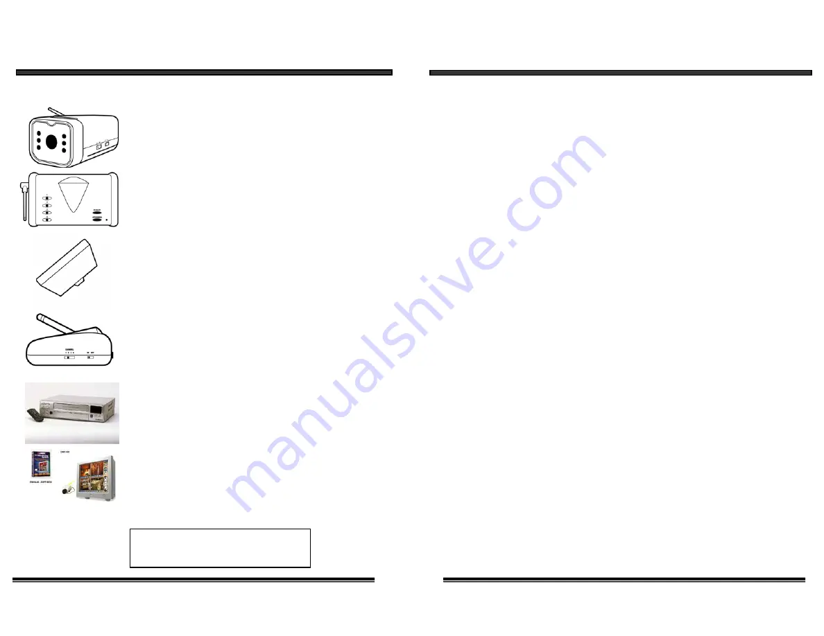
The following optional accessories are available to add to your existing system
Accessory Camera - Used to view other camera locations
(Available in B&W and Color)
Accessory Receiver - Used to connect and view picture
on a T.V.
Accessory Transmitter - Used to turn a wired camera into
a wireless device
Time Lapse VCR - Used to record key events. Available
in 24 or 960 Hour Time Lapse VCR
Digital Monitoring System - Connects to PC to provide
digital recording and remote security monitoring via
computer
FOR MORE INFORMATION
www.strategicvista.com
7. DAMAGE REQUIRING SERVICE
- Unplug this product from the wall outlet
and refer servicing or repairs to qualified service personnel under the following
conditions
:
a. When the power supply cord or plug is damaged.
b. If liquid has been spilled or objects have fallen into the product.
c. If the product has been exposed to rain or water.
d. If the product does not operate normally by following the operating instructions.
Adjust only those controls that are covered by the operating instructions.
e. If the product has been dropped or the cabinet has been damaged.
f. When the product exhibits a distinct change in performance.
8. REPLACEMENT PARTS
- When replacement parts are required, be sure the
service technician has used replacement parts that are specified by the manufacturer
or have the same characteristics as the original part. Unauthorized substitutions
may result in fire, electric shock, or other hazards.
9. SAFETY CHECK
- Upon completion of any service or repairs to this video
product, ask the service technician to perform safety checks to determine if the
video product is in proper operating condition.
10. An appliance and cart combination should be moved with care.
Do not place this equipment on an unstable cart, stand, or table.
The equipment may fall, causing serious injury to a child or adult,
and serious damage to the equipment. Wall or shelf mounting
should follow the manufacturer's instructions and should be
done with a mounting kit approved by the manufacturer.
3
Accessory Battery Compartment for Camera- Wireless
Camera allows user option of battery Compartment or
AC adaptor.
Accessory Battery Compartment for Monitor- Wireless
Monitor allows user option of battery Compartment or
AC adaptor


