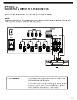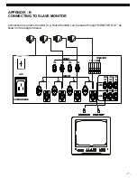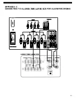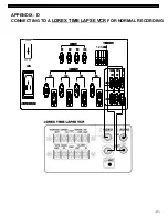
MONITOR CONNECTIONS
1. Camera 1 Input
Connect one end of the supplied 65ft cable to
the first wired camera, the other end to camera
Input 1.
2. Camera 2 – 4 Inputs
Connect optional/additional cameras to the
camera 2-4 inputs using either the DIN or
BNC camera inputs.
-13-
If the system does not function properly, please check the following points.
TROUBLE SHOOTING
MONITOR
PROBLEM
REMEDY
Too dark or bright picture
Readjust the CONTRAST or BRIGHTNESS controls
NO POWER
Check for AC connection
Poor picture quality
Clean the camera lens. Readjust the CONTRAST or
BRIGHTNESS controls
Picture but no sound
Adjust the VOLUME
Shrinking picture
Check the condition of the POWER source
No Picture
Picture Flickering or
Over Exposed
Check the cable for any lose connection
Make sure the camera is not facing any direct light
or sunlight
CAMERA
1
2
3
4
CH4
AC INPUT:90~250V,50/60Hz
OFF ON
AC IN
CH1
CH2
CH1
CAMERA INPUT
CH3
CH3
AUDIO INPUT
CH2
AUDIO
VCR
OUT
1 2 3 4
CH4
VIDEO
SLAVE
OUT
TRIGGER OUTPUT
GND
VCR
IN
OFF
ON
POWER


