


7
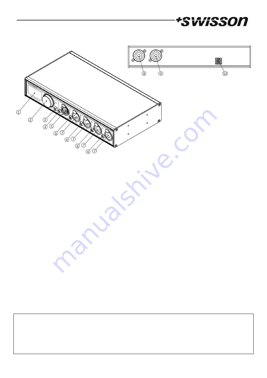
Device Overview
1.
OLED display.
2.
Encoder wheel / [OK] button. The encoder is primarily used for selecting menu items by turning the knob. It
also functions as a push button. This manual refers to this button simply as [OK] button or [OK].
3.
[Cancel] button.
4.
Ethernet port button [E].
5.
Ethernet port (RJ45 Neutrik etherCON socket).
6.
Output port buttons [1] – [4]. These push buttons are used to change to which universe the respective output
is connected. An output port status LED showing status information is located directly below each of those
buttons.
7.
Signal output ports 1 – 4.
8.
Neutrik powerCON input socket.
9.
Neutrik powerCON output socket.
10.
USB type-B socket for firmware updates.
Mains Connection
The user must supply a suitable power cable. He may then either hard-wire the power cable to the building’s electrical
installation, providing an easily accessible power on/off switch close to the device, or install on the power cable a
grounding-type (earthed) mains plug that is suitable for the local power outlets, following the power plug
manufacturer’s instructions. Consult a qualified electrician, if you have any doubts about the proper installation.
A blue Neutrik powerCON NAC3FCA cable mount connector must be used to supply power at the XND-4’s power input
socket.
Warning! For protection against dangerous electrical shocks, the device must be grounded (earthed). The
local AC power source must be supplied with both overload and ground-fault (earth fault) protection.
Important! Only attach or remove a Neutrik powerCON connector while it is connected to the mains to
apply or cut power in an emergency situation, as by doing so may cause arcing at the terminals that will
damage the connectors.


