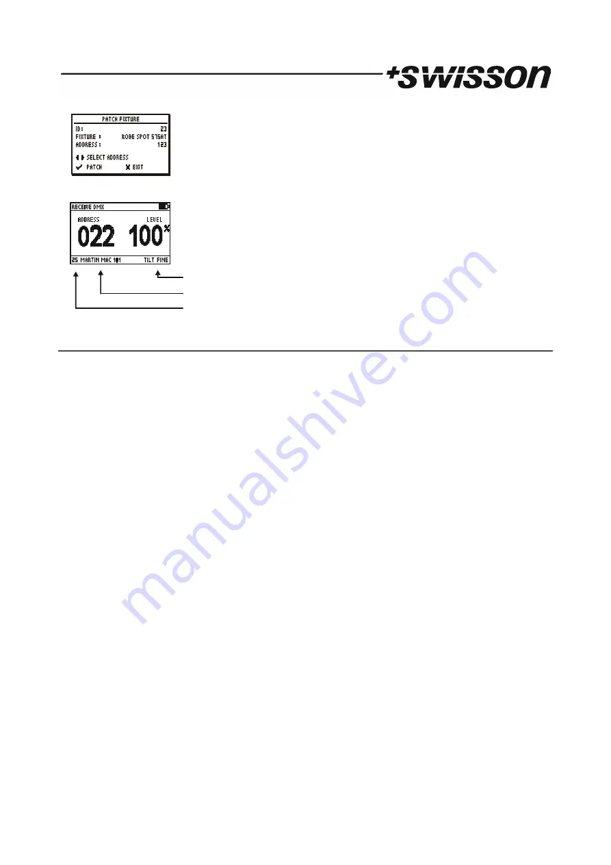
Swisson XMT-120A User Manual Download Page 17

ID

The fixture ID. It will be incremented automatically. 

FIXTURE


Name of the fixture type. 

ADDRESS

The patch address for the fixture. 

The XMT proposes the next free DMX address as the patch address. This 

address can be changed with the [CH+] and [CH-] buttons.

Press [OK] to patch the device.

If a fixture is patched, the receive DMX mode and the send DMX mode will show 

information about the current channel on the bottom of the screen. 

 18.2  EDIT FIXTURES

The fixture types can be created and modified on the XMT itself or more conveniently with the XMT Fixture Library 
Editor on a computer. 

Choose the EDIT FIXTURES item with [UP] or [DOWN] button.

Press [OK] to enter the fixture type editor.

The entire patch will be cleared.

Press [OK] to confirm. 

Use [+] and [-] button to edit a fixture or CREATE NEW FIXTURE to create a new one.

NAME

Name of the fixture.

NUMBER OF CH

Number of DMX channels used by this fixture.

CHANNEL DEF

Definition of the channel description.

DELETE FIXTURE

Delete the fixture definition.

Name

Use [+] and [-] buttons to select NAME.

Select the cursor position by pressing [CH+] or [CH-] and change the character at the cursor position with [+] and [-].

Pressing [0] will set the character to a blank space. 

When done press [OK] and the name will be saved. Press [CANCEL] keep the old name.

Number of channels

Use [+] and [-] buttons to select NUMBER OF CHANNELS.

Use [+] and [-] to set the number of channels for the fixture

Channel definition

Use [+] and [-] buttons to select CHANNEL DEF.

A list with all channels of the fixture appears. 

Use [+] and [-] buttons to select the channel.

Press [OK] to edit the channel description. 

Select the cursor position by pressing [CH+] or [CH-] and change the character at the cursor position with [+] and [-].

Pressing [0] will set the character to a blank space. 

When done press [OK] and the name will be saved. Press [CANCEL] keep the old name.

17     PRELIMINARY

Parameter Description
Fixture Name
Fixture ID

Summary of Contents for XMT-120A

Page 1: ...XMT 120A XMT 350 DMX Measurement Tool Tester USER MANUAL Distributor www techni lux com Phone 407 857 8770 Fax 407 857 8771 Email sales techni lux com...

Page 2: ...Revisions History Revision Description Date 1 First Draft 23 08 12 1 1 Draft English XMT 120A and XMT 350 ler 09 10 12 1 3 Edited boc 22 03 13 2 PRELIMINARY...

Page 3: ...EDIT MODE 12 13 6 REFRESH RATE 13 14 CABLE TESTER 13 15 CHANEL TRACER 13 16 TIMINGS 15 17 SEQUENCE 15 17 1 EDIT SEQUENCE 16 17 2 PLAY SEQUENCE 16 17 3 DELETE SEQUENCE 16 18 FIXTURES 16 18 1 PATCH FIX...

Page 4: ...g analysis sequence editor channel tracer dip switch display and Min Max display this device is ideal for troubleshooting and resolving DMX 512 signal challenges and yet remains very simple to operate...

Page 5: ...E The operating mode can be selected by pressing the mode button VALUE UP Increase DMX value NAVITGATE Use to navigate up in the user menu DISPLAY LCD display with LED backlight VALUE DOWN Decrease DM...

Page 6: ...e refer to the Power Settings chapter on how to change this behavior 7 USB Port The USB port is used to power the XMT and to connect it to a PC Any 5V USB adapter which is capable to supply 150mA can...

Page 7: ...MX in port If a DMX signal is received without any errors the data of the DMX signal will be displayed Choose the DMX address with CH and CH buttons The corresponding level will be shown in real time...

Page 8: ...tons Press OK to confirm Press CANCEL twice to exit the receiver options There are 32 scenes which are accessible from the receive DMX mode as well as from the send DMX mode Storing the received signa...

Page 9: ...Note This option only applies to the Normal display mode 12 SEND DMX Press the MODE button and choose SEND DMX Now press the OK button to enter the send mode Connect your DMX fixtures to the DMX out...

Page 10: ...E Set the DMX refresh rate for the DMX transmitter 13 1 CLEAR ALL CHANNELS In send DMX Mode Press OK to access the send options Choose CLEAR ALL CHANNELS with the UP and the DOWN button Press OK to co...

Page 11: ...he send options Note The scenes in receive DMX mode and in send DMX mode are shared All 512 channels are stored into a scene Storing to a scene overwrites the scene s previous content The scenes can b...

Page 12: ...the EDIT MODE item with the UP DOWN buttons Press OK to change the edit mode The edit mode can be NORMAL or DIRECT Press Cancel to exit the send options Note The edit mode setting does not affect grou...

Page 13: ...to the DMX out port The XMT scans all pin connections automatically If the connection between a pair of pins is OK it s indicated by a straight line connecting the pins Pin 2 is connected to pin 3 Thi...

Page 14: ...and resume the tracing When stopped a small cursor appears The position of the cursor is displayed on the bottom right of the screen The first value shows the DMX level and the second value shows the...

Page 15: ...ipment 44 frames per second maximum speed when sending all 512 channel 44 frames per second only possible when sending less than 512 channel Compliant to standard but may cause problems with some equi...

Page 16: ...ease decrease the fade time 17 3 DELETE SEQUENCE Choose the DELETE SEQUENCE item with UP DOWN buttons and press OK Press OK again to confirm 18 FIXTURES Press the MODE button and choose FIXTURES Now p...

Page 17: ...re NUMBER OF CH Number of DMX channels used by this fixture CHANNEL DEF Definition of the channel description DELETE FIXTURE Delete the fixture definition Name Use and buttons to select NAME Select th...

Page 18: ...date of the XMT 20 1 ENTER NAME Choose the ENTER NAME item with UP or DOWN button Press OK to enter the name dialog Select the cursor position by pressing CH or CH and change the character at the curs...

Page 19: ...OFF IF IDLE Automatic turn off time for the XMT when battery operated BACKLIGHT BRIGHTNESS Choose the BACKLIGHT BRIGHTNESS item with UP or DOWN buttons Press OK to change the backlight brightness fro...

Page 20: ...l discovery is completed The main screen shows a list of the RDM devices discovered The device description and the DMX address is displayed for all found RDM devices The currently selected device is i...

Page 21: ...r off with OK DEVICE DETAILS RESET WARM RESET Press OK to start a warm reset of the RDM device COLT RESET Press OK to start a cold reset of the RDM device DEVICE HOURS Operating hours of the RDM devic...

Page 22: ...the user to know which devices has already been readdressed patched The first item on the list is RESTART PATCH Select this Item to restart the patch In this case all devices will be marked with the...

Page 23: ...X in port is an isolated receiver Is the XMT connected to a PC the DMX in port might be a ground referenced receiver when the USB is grounded Is the XMT connected to a DMX controller with a ground ref...

Page 24: ...y resolution 128x64 pixel FLASH memory 16MBytes DMX in port Neutrik 5 pin male connector DMX out port Neutrik 5 pin female connector DMX ports electrical standard ANSI E1 11 ANSI E1 20 USB port Micro...

Page 25: ...25 PRELIMINARY...

Reviews: