background image


Page 4


3434.505.02 

Version 2.0 

2  INSTALLATION 

2.1 

First setup 

If  you  have  ordered  the  optional  internal  battery  [3434.980],  you  have  to  mount  it  in  the  camera 
before the first use: 

1.  With  the  delivered  tool, remove  the  screw  that  block  the 

battery cover (point 33 of chapter 

1.1.4

) and open battery 

cover. 

2.  Inside  the  camera,  find  the  cable  with  the  connector 

corresponding  to  the  battery  pack,  and  pull  it  (gently)  a 
little bit out of the camera. 

3.  Enter  the  battery  pack  in  the  location  (with  the  wires  on 

the external). 

4.  Connect  the  connectors  together  and  then  insert  totally 

the battery. 

5.  Close  the  battery  cover  and  block  it  with  the  screw 

removed on point 1 using the delivered tool. 


Remarks : 

  The battery is delivered uncharged. 


  Use  only  the  delivered  battery.  Use  of  other  kind  of  battery  can  seriously 

damage  the  camera  due  to  the  charger  type;  in  this  case  the  camera 
guarantee will be loosed. 


2.2 

Installation of the camera 

The  photofinish  camera  must  be  installed  exactly  on  a  virtual  extension  of  the  finish 
line and the sensor must be vertically perpendicular to this line. 


The inclination of the camera is important for the ease of judgment. In general, a vertical inclination 
of 8

o

 to 10

o

 is used for the rowing and the canoeing, and of 10

o

 to 20

o

 (in relation to the middle of 

the finish line) for the cycling, the horse-racings and of greyhound. For athletics, an angle of 25

o

 to 

30

o

  is  recommended  in  relation  to  the  farthest  lane  in  order  to  prevent  the  competitors  in  the 

foreground masking another. 

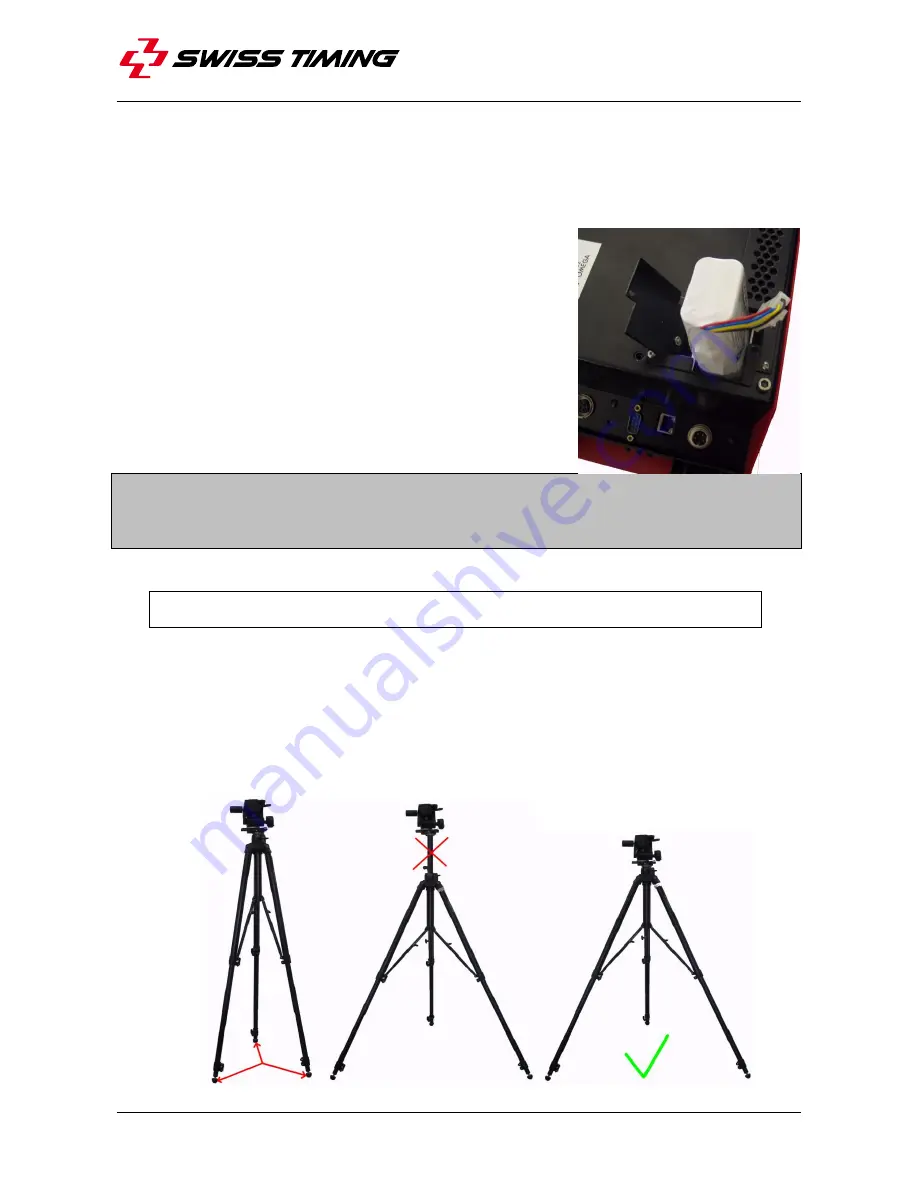
  Centre the tripod on the extension of the finish line. If it is equipped with a spirit level, align 

the  bubble  precisely  in  the  middle  of  the  reference  mark.  Then  slowly  tighten  all  screws 
checking  bubble  does  not  move.  For  a  better  stability,  spread  the  legs  as  far  apart  as 
possible and do not raise the central extension tube: 


Summary of Contents for OSV-STAR

Page 1: ...3434 505 02 Version 2 0 Edition November 2012 SCAN O VISION STAR CAMERA OSV STAR User s Manual ...

Page 2: ...t to refuse all guarantees if this condition is not fulfilled If the installation includes a horn be sure to maintain a sufficient security distance from the public Documentation Updates Swiss Timing Ltd reserves the right to make improvements in the products described in this documentation at any time without prior notice Furthermore Swiss Timing Ltd reserves the right to revise this documentatio...

Page 3: ...finitions 3 2 INSTALLATION 4 2 1 First setup 4 2 2 Installation of the camera 4 2 3 Choice of the lens 5 2 4 Lens 6 2 5 Lens mounting 7 2 6 Removing the lens 7 2 7 Wiring the installation 8 2 8 Power on and power off 8 2 9 Loading of the internal battery 8 2 10 Indicators 9 3 SOFTWARE 10 3 1 Computer 10 3 2 Screen saver 10 3 3 Software installation 10 3 4 Network card configuration 11 3 5 Improve ...

Page 4: ... LTD 4 2 GPS 17 4 3 Optic fibre connection 17 4 4 WiFi 17 4 5 Working on external battery 17 5 PROPERTIES 18 5 1 Power supply 18 5 2 Connections 18 5 3 Technical characteristics 19 6 MAINTENANCE AND PROTECTION 20 6 1 Storage 20 6 2 Maintenance 20 6 3 Camera reset 20 7 APPENDIX 21 7 1 Abbreviations and symbols 21 7 2 Index of tables and figures 21 7 3 Version history 21 ...

Page 5: ......

Page 6: ......

Page 7: ... colour camera without matrix alignment with remote control of the focus and aperture of the lens for new lenses for new lenses with electric command of the focus Colour camera with matrix alignment standard Colour camera with matrix alignment compact Colour camera with matrix alignment and remote control of the focus and aperture of the lens standard Colour camera with matrix alignment and remote...

Page 8: ...dle to carry the camera 2 Initial alignment sight 3 Axis of alignment 1 1 2 Front view 10 Fixing for lens protection 11 Reference mark hole for lens mounting 12 Latch for unlocking the lens 13 Nikon mount for lens fixing with protective cap 14 Clutch button of the remote control lens ...

Page 9: ...Bottom view 30 Air entry with filter 31 Fixing screws for air filter 32 Cover for battery access 33 Screw for opening battery cover 34 Descriptive sticker with model and serial number 35 Fixing for photo support UNC 3 8 36 Other fixing points 4 x M6 depth 16mm 1 2 Definitions The camera is typically supplied with a support permitting the setting of its position according to 4 axes here are the def...

Page 10: ...mera due to the charger type in this case the camera guarantee will be loosed 2 2 Installation of the camera The photofinish camera must be installed exactly on a virtual extension of the finish line and the sensor must be vertically perpendicular to this line The inclination of the camera is important for the ease of judgment In general a vertical inclination of 8o to 10o is used for the rowing a...

Page 11: ...you the lens corresponding exactly to your camera model 9051 6255 9051 6256 9051 6253 9051 6254 9051 6252 STAR 110 STAR 210 STAR 1010 STAR 2010 STAR 220 MOT MAN Aperture MAN MAN MAN MOT MOT MOT MAN MAN MOT MOT MOT MOT MAN MOT MAN MOT MOT MOT MOT MAN MAN MAN MOT MOT MAN MAN Focus Aperture Focus Aperture Focus Aperture Focus Aperture Focus Zoom lens 24 70mm f 2 8 4 Nikon mount Zoom lens 70 300mm f 4...

Page 12: ...nd the middle of the track the final setting must be done when viewing the image on the computer OSV STAR software in setting mode D Hood Removable mechanical part Must be mounted to protect the lens from sun and rain E Aperture lock In the locked position the aperture cannot be adjusted manually For camera with lens remote control set the aperture ring A to the highest number and move the apertur...

Page 13: ...ers If a hood is delivered with the lens you should always use it 2 6 Removing the lens Before the dismounting the camera it is necessary to remove the lens To do this hold the lens in the left hand with a finger of your right hand push on the unlocking latch 1 see point 12 of chapter 1 1 1 and turn the lens clockwise 2 until it is free about 1 6 turn With and cameras a plastic tool is delivered t...

Page 14: ...12VDC can be used instead the AC DC power adaptor when no mains power is available at the site of the camera option battery cable 3330 618 2 8 Power on and power off When the power cable is plugged the camera starts itself The green LED on the rear face should be lit The green LED of the AC DC adaptor should also be lit At power on the camera initializes itself during about 80 seconds then at leas...

Page 15: ...right side of the camera is too high Camera switched on non vertical sensor Seen from rear the left side of the camera is too high Indicates that the LED blinks The faster the LED blinks the closer the sensor is to vertical ETHERNET In the connector the left LED indicates Off No connection Green Connection at 100Mbps Orange Connection at 1Gbps normal state of use The right LED blinks when there is...

Page 16: ...or PCMCIA can be added for example for a laptop the card NETGEAR Gigabit PC Card GA511 3 2 Screen saver Please deactivate any screen savers while the system Scan O Vision is in use If the computer enters the screen saver sleep or hibernation mode while the software is running the connection to the camera could be lost The connection is automatically re established when exiting these modes but if y...

Page 17: ...tocol address The network card to which the camera is connected must be configured Press the windows button Start Settings then Control panel Double click on Network Connections Right click on the line corresponding to the network card on which the Scan O Vision camera is connected and choose Properties Deactivate all services except Client for Microsoft Networks and Internet Protocol TCP IP Highl...

Page 18: ...s button Start Settings then Control panel Double click on System Click on the Hardware tab and then on the Device Manager button Right click on the network adapter where the camera is connected and select Properties Select the Advanced tab select Link Speed Duplex Mode in the list and change the value from Auto Negotiation to 1000Mbps Full Duplex Note the previous text in magenta may change depen...

Page 19: ... right click and select Properties Select the Policies tab Verify the Enable write caching on the disk is checked If not please click on it to check it Close the hard disk properties by clicking on the OK button If you have several hard disks repeat the latest points for every hard disk Close the Device manager System Properties and Control Panel window 3 6 Use of the Scan O Vision software Please...

Page 20: ... www swisstiming com In some cases the firmware of the camera must also be updated see chapter 3 9 In any case it must be current with the version of the main software if this is not the case a warning message will be displayed when you launch the Scan O Vision application Incompatible hardware software version ...

Page 21: ...a After a few seconds the software prompts you to select the archive directory you want to install select the C OSV STAR Camera_firmware directory and then the sub directory with the latest version of firmware for your camera model If the number 555 is present on or near the descriptive sticker see location on chapter 1 1 4 you should use firmware OSV_STAR_CAMERA_MODEL_v_ in other case use firmwar...

Page 22: ...STAR camera and exit this software is displayed in the bottom of the window You can now exit the Firmware exe utility tools by clicking on the icon You have to unplug the power connector of the camera wait some seconds and plug it again to restart the camera Once the camera has finished rebooting you can start the OSV7 software ...

Page 23: ...can O Vision and a water resistant antenna with magnetic fixation and 5 metres of cable Remark Normally in order to obtain a good GPS signal reception the antenna must be installed outside of the building Other antenna models are available on the market in order for them to be compatible with the Scan O Vision they must have a SMB connector and must support a 5V power supply 4 3 Optic fibre connec...

Page 24: ...ep 2 START 12V sep 3 READY 4 START 5 FINISH 6 READY 12V sep With 3434 620 provided cable Start Input impulsion with READY Tuchel 4pF 1 READY 2 START 12V sep 3 START 4 READY 12V sep 1 2 3 Finish Input impulsion red and black Banana Red Banana FINISH 12V sep Black Banana FINISH RS232 input output RS232 with RTS CTS Sub D 9pM 1 DCD 2 RX 3 TX 4 DTR 5 GND 6 DCR 7 RTS 8 CTS 9 RI 1 2 5 6 9 SERIAL ETHERNE...

Page 25: ... 0 kg STAR 210 3 9 kg 4 1 kg STAR 220 3 9 kg 4 1 kg STAR 1010 4 8 kg 5 0 kg STAR 2010 4 9 kg 5 1 kg STAR 2020 4 9 kg 5 1 kg Working temperature 0o C to 50o C Storage temperature 20o C to 70o C Protection IP43 Timing accuracy 1ppm Autonomy of internal battery option about 60 minutes at 20o C Electronic inclinometer instead of bubble level Lenses Nikon AF Resolution 2048 pixels Acquisition speed 100...

Page 26: ...fully recharged 6 2 Maintenance Never touch the lens glass of the lenses or camera with your fingers After use please always replace the protection caps It is recommended to clean the glass of the lenses and camera regularly with a photographic link free cloth 6 3 Camera reset If the camera connection Ethernet cannot be established between the computer and the camera Exit the OSV STAR software Wit...

Page 27: ...X 7 1 Abbreviations and symbols Abbreviations Symbols 7 2 Index of tables and figures Index of tables Index of figures 7 3 Version history Version Date Modifications since last version 1 9 01 01 10 Modifications STAR 220 2 0 13 11 12 Modifications camera version 555 chapter 3 9 ...

Page 28: ...Page 22 3434 505 02 Version 2 0 NOTES ...

Page 29: ...P O Box 138 rue de l Envers 1 Phone 41 32 488 36 11 2606 Corgémont Switzerland Fax 41 32 488 36 09 www swisstiming com info swisstiming com SWISS TIMING LTD SWISS TIMING LTD ...

Reviews: