Swegon WISE Damper a Instructions For Use Manual Download Page 2

WISE 

Damper

2

Swegon reserves the right to alter specifications.                          20180620


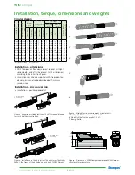
Figure 2. Installation in the duct system The ducts must be firmly 
fixed to the frame of the building on each side of WISE Damper.

1.  WISE Damper
2.  FSR Clamp
3.  Sound attenuator 

1.  WISE Damper
2.  FSR Clamp

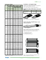
Installation, torque, dimensions and weights

Circular design 

Si

ze Ø (

m

m

)

A (

m

m

)

Ins

ta

lla

ti

on

 d

im

ens

io

ns


(mm

)

Normal 

motor

Spring return

Flow range

To

ler

anc

e Q

*

 ±

5%


w

ith a

t l

ea

st ±

x l

/s

Min. (0.6 

m/s)

Max. (10 

m/s)

To

rq

ue

 (N

m

)

W

eig

ht

 (k

g)

C (

m

m

)

To

rq

ue

 (N

m

)

W

eig

ht

 (k

g)

l/s

m

3

/h

l/s

m

3

/h

100 574 584

5

2.5

11

5

3.0

5

18

79

285

2

125 574 584

5

2.8

24

5

3.3

7

26

123

443

2

160 574 584

5

3.2

33

5

3.7

11

40

202

728

2

200 574 584

5

3.7

19

5

4.2

18

65

315

1134

3

250 574 584

5

4.3

13

5

4.8

30

108

491

1768

5

315 600 610

10

5.2

0

10

6.2

50

180

780 2808

8

400 830 850

10

8.0

0

10

9.0

87

314 1257 4526

13

500 830 850

10

9.9

0

10

10.9 135 486 1964 7071

20

630 915 935

15

13.5

0

20

14.5 187 674 3118 11225 32

*

Installed according to the instructions

Figure 4. Dimensions, WISE Damper circular and WISE Damper 
circular with spring return. 


125

125

A

ø

C

Figure 1. Requires a straight section of 2 x Ø for sound attenua-
tors with baffle or centre body.

Installation – all designs

•  WISE Dampers’ air flow measurement requires a straight 

section before and after the product (in the air direction) 
according to the installation figures.

•  Instructions for Use are supplied with the product on 

delivery, but can also be downloaded from www.
swegon.com.

Installation – circular version

•  Installation is position dependent.

Figure 3. Straight section requirements, circular ducts.
1-5: Quantity Ø before the product: 0 x Ø.
6: Quantity Ø before the product: 2 x Ø.

*

Cleaning hatch

1.

2.

3

*

.

4.

5.

6.

Summary of Contents for WISE Damper a

Page 1: ...equired position and then locked Do not forget to disable the lock after working on it Other risk When the product is voltage fed the damper will be either open or close and there can be a certain ris...

Page 2: ...91 1768 5 315 600 610 10 5 2 0 10 6 2 50 180 780 2808 8 400 830 850 10 8 0 0 10 9 0 87 314 1257 4526 13 500 830 850 10 9 9 0 10 10 9 135 486 1964 7071 20 630 915 935 15 13 5 0 20 14 5 187 674 3118 112...

Page 3: ...000 14400 40 1000 x 500 15 28 6 20 30 6 429 1545 5000 18000 50 1200 x 500 15 32 7 20 34 6 514 1851 6000 21600 60 1400 x 500 15 36 8 20 38 7 600 2160 7000 25200 70 1600 x 500 15 40 8 20 42 8 686 2470 8...

Page 4: ...be blue Pressure tube red 24 V DC U Ground Y Figure 9 WISE Damper connections Connections LED Explanation Not paired Colour Type Energized White Permanent Selected in TuneWISE White Flashing fast Prep...

Page 5: ...sor does not hang outside the product Check that the VOC sensor is connected to the right input Cleaning Ideally the product should be cleaned in connection with the cleaning of the rest of the ventil...

Page 6: ...lug from tubular damper casing Figure 13 Tighten the counter nut against the tubular damper casing so that it presses the seal against the tubular damper casing Replacing the damper motor Figure 15 Di...

Page 7: ...lamp on the motor is fitted according to one of the designs shown in figure 21 or 22 4 Tighten the nuts on the spindle clamp 5 Connect the cable Figure 21 For damper position Normally closed the dampe...

Page 8: ...pread spectrum modulation techniques Person responsible for this declaration Name Ingvar Hagstr m Factory Manager Tomelilla Address Industrigatan 5 273 21 Tomelilla Sweden Date 170131 This declaration...

Reviews: