


W3/W4.170420
All rights to changes reserved.
7
www.swegon.com
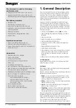
2.3.2 Ceiling mounting
The ventilation unit can be mounted on the ceiling with a
ceiling mounting bracket which is available as an accessory.
Fasten the ceiling mounting frame in ceiling anchor
sleeves with four M8 threaded rods. The length of rods
must be adjusted so that they will be positioned max.
15 mm under the inner surface of the ceiling mounting
bracket. Otherwise, the rods will hit the upper surface of
the ventilation unit. Install at least three threaded rods in
the corners of the ceiling mounting bracket. To avoid a
possible collision with the ducts, one of the threaded rods
can be located in the hole next to the corner.
Screw in the M8 nuts onto the threaded rods to such a
height that the ceiling mounting bracket will be hori-
zontal when the top of the frame goes against the nuts.
Fit the ceiling mounting bracket through the selected
holes towards the nuts of the threaded rods and lock
the frame into position with nuts from underneath.
Adapt the installation height so that the locking pins in
the mounting bracket’s front section will stay sufficiently
far below the ceiling.
Important
Improper tightening of the ceiling moun-
ting bracket can cause the bracket to warp
and the unit will not fit in it.
!
!
Run the mounting hooks through the assembly open-
ings above the ventilation unit and secure them with
tension rivets. Position the hooks so that the sharp point
is facing the rear side of the ventilation unit.
The hooks must absolutely not be secured with riv-
ets directly above the ventilation unit.
Run the power supply and control cables through the
ceiling mounting bracket.
Screw the anti-vibration mountings in position on the
lower edge of the rear wall of the ventilation unit before
lifting the unit onto the bracket. The ventilation unit’s
door and heat exchanger can be removed to make it
easier to lift the unit. See the ”Service” section.
Lift the ventilation unit so that the hooks go through
the fastening holes in the mounting bracket. The venti-
lation unit is locked in place when the locking pins are
touching the front plate of the mounting frame and
can be seen from the openings on the front edge of the
frame. (see picture)
x
Finally adjust the position of the ventilation unit using
the adjustable anti-vibration mountings, so that the unit
tilts backward by a few degrees. Make sure that a hard
twist is not subjected to the ceiling mounting bracket.
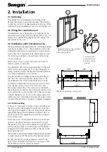
2.4 Condensate discharge
Connect the discharge hose to the ventilation unit’s con-
densate discharge connection (3/8” male threads). The
condensate is led off to a floor drain or the like using a
hose or pipe with an inner diameter of at least 12 mm.
The hose must not be led off directly to the drain. The
tube must not have a second water trap or be run hor-
izontally. The damming height of the water trap should
be at least 100 mm.
Check that the condensate discharge outlet is not
clogged and check its outflow by pouring water on the
bottom of the ventilation unit. The condensate discharge
connection is located on the rear of the unit under the
heat exchanger.
A hose to lead off the condensate is available as an
accessory (CDH3). The hose has a ready-made loop that
serves as a water trap.
200 mm
3/8” male thread
The metal water trap (UVL) is available as an accessory.


