www.actionair.co.uk
[email protected]
11. Control Modes (3 positions)
(Refer to figure 8)
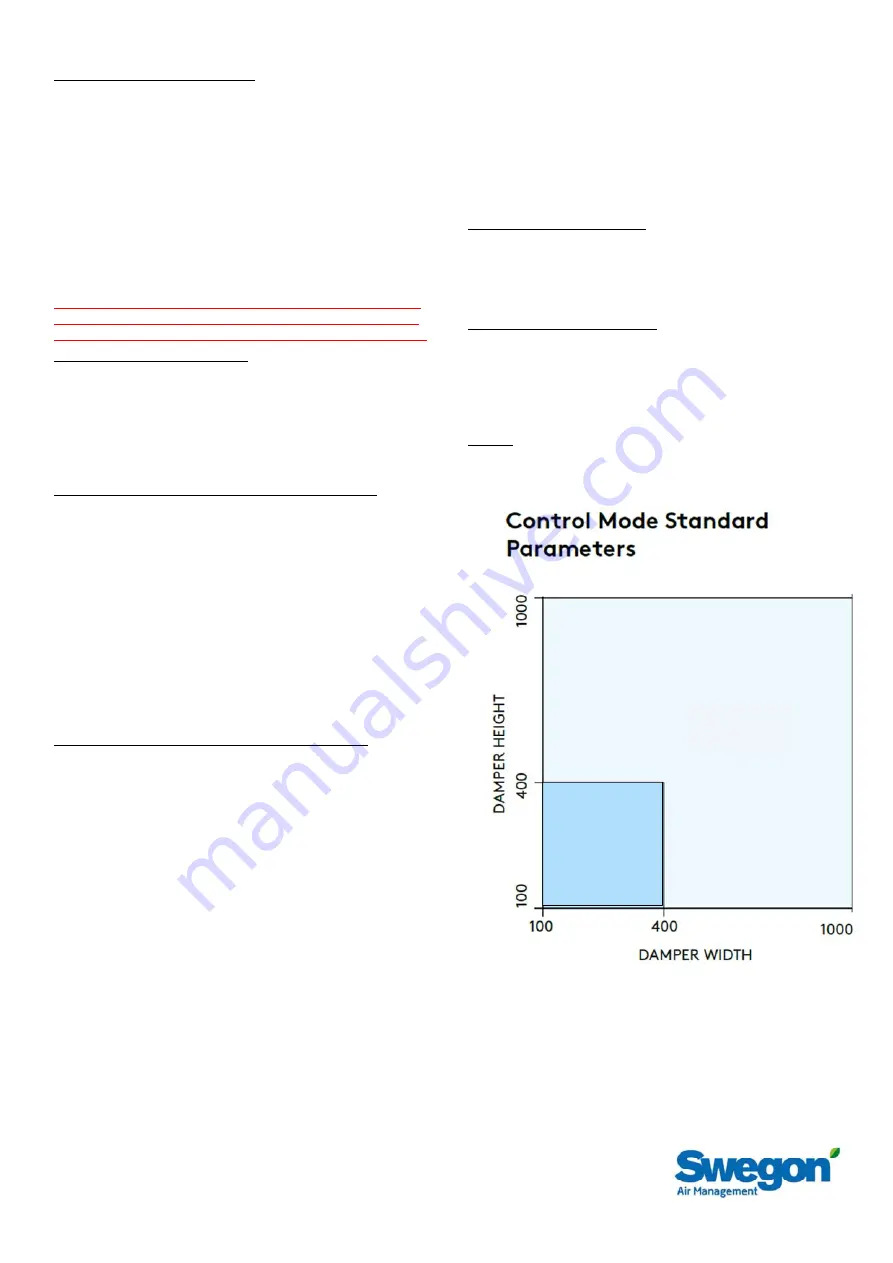
Two sizes of Control Modes are utilised - 5.10Nm & 15Nm.
Correctly sized Control Modes are designed to fit only to the
relevant sized damper. (See ‘Control Mode Standard
Parameters’ figure) (Refer to figure 5)
Remove transit plate from damper mounting plate and recycle.
Mount actuator to damper mounting brackets & secure with
screw & washer provided - 5Nm Max. (Refer to figure 6)
Its important to fit the 2 spacers provided. (Refer to figure 6)
Never operate the manual override (shaft) when actuator is
connected to power supply.
Actuators will only work if Safety temperature sensor (ExPro TT)
is properly connected. (Refer to figure 7)
*IMPORTANT* - please ensure damper blades are in the fully
closed position prior to mounting actuators. Failure to do so
may damage drive shafts and render the damper inoperable.
12. Mechanical Operation check
As an interim check, the damper should be manually reset and
released using the manual reset key provided, (refer to Control
Mode label) to ensure that correct mechanical operation is
achieved. This feature may be used for system commissioning
when electrical power is unavailable. Note however, the ExPro TT
is not operable without electrical power, and the damper will
not close automatically should a temperature rise or fire occur.
13. Safety Temperature Sensor (ExPro TT) Installation (When not
affixed to damper casing, 210mm wide casing option only)
Select a suitable position for the ExPro TT on the duct as follows:
Deck Installations – Must be anywhere below the damper.
Bulkhead installations – Ideally this should be anywhere in the top
half of the duct.
Position the self-adhesive ExPro TT drilling template label
provided in the appropriate position on the duct.
Using a 2.5mm dia bit, drill the two ExPro TT fixing holes.
Using a 10mm dia drill, drill the central hole.
Remove sharp edges.
Push the ExPro TT through the duct and ensure that both screws
are used to hold it securely in position.
The ExPro TT cable must not be shortened, and care must be
taken not to damage it.
14. Electrical Connection and Final Operational Test
The unit must be wired as described in the Application and
Wiring section 17. When power is available, the unit must be
checked for electrical operation. Power on to motor open, power
off to spring close. The unit must also be checked by moving
and holding the test switch on the ExPro TT to confirm that the
damper closes. When pressure is removed from the switch the
damper will re-open. This may be done after the initial
installation test, to provide periodic operation of the damper to
simulate actual fail-safe closure under fire conditions.
Schischek actuators are equipped with a universal supply unit
working at a voltage range from 24 to 230 VAC/DC. The supply
unit is self-adjustable to the connected voltage! The safety
operation of the spring return function works if the supply voltage
is cut. For electrical connection inside hazardous areas, an EEx-
e terminal box, certified in accordance with ATEX is required (E.G
ExBox XNNN00578)
Electrical ATEX (Ex) rated as below
Fail-safe is by means of an ExPro-TT which operates at 72 °C, or
if power supply is interrupted.
A manual test button (Refer to figure 7) allows periodic
operation of the damper for testing purposes, simulating actual
fail-safe release under fire conditions.
The associated electrical Control Modes are available in one
Universal version with 24 – 230V AC/DC supply.
ExMax ATEX classification;
Explosion proof Zone 1, 2, 21 & 22 gas & dust PTB-certified
II 2(1) G Ex d [ia] llC T6
ll 2 G Ex d ia llC T6
ll 2 D Ex tD A21 IP66 T80 oC
ATEX 94/9/C, IEC-Ex
RedMax ATEX classification;
Explosion proof Zone 2 & 22 gas & dust PTB-certified
II 3(1) G Ex nC [ia] llC T6
ll 3 G Ex nC ia llC T6
ll 3 D Ex tD A22 IP66 T80 oC
ATEX 94/9/EC
IEC-Ex
InMax
actuators are IP66 classified
NOT ATEX classified and only for use in safe areas
15Nm
5.10 Nm
Figure 5