background image

SWAGTRON

TM

 SWAGDRONE

TM

 150-UP Racing Quadcopter Quick Start Guide

4

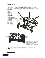
1.0 SwagDrone Parts 


+

Modern industrial and modular design helps improve product performance.


+

Advanced 5.8ghz live video for an unforgettable, first-person visual (FPV) experience.


+

Modern flight control system for acrobatic flight routines such as rolls, flips, and race 

course moves. 

*  Read this guide in its entirety before attempting to use the SwagDrone 150-UP

*  Always extend the Receiver Antennas before flight.

2.0 Remote Control

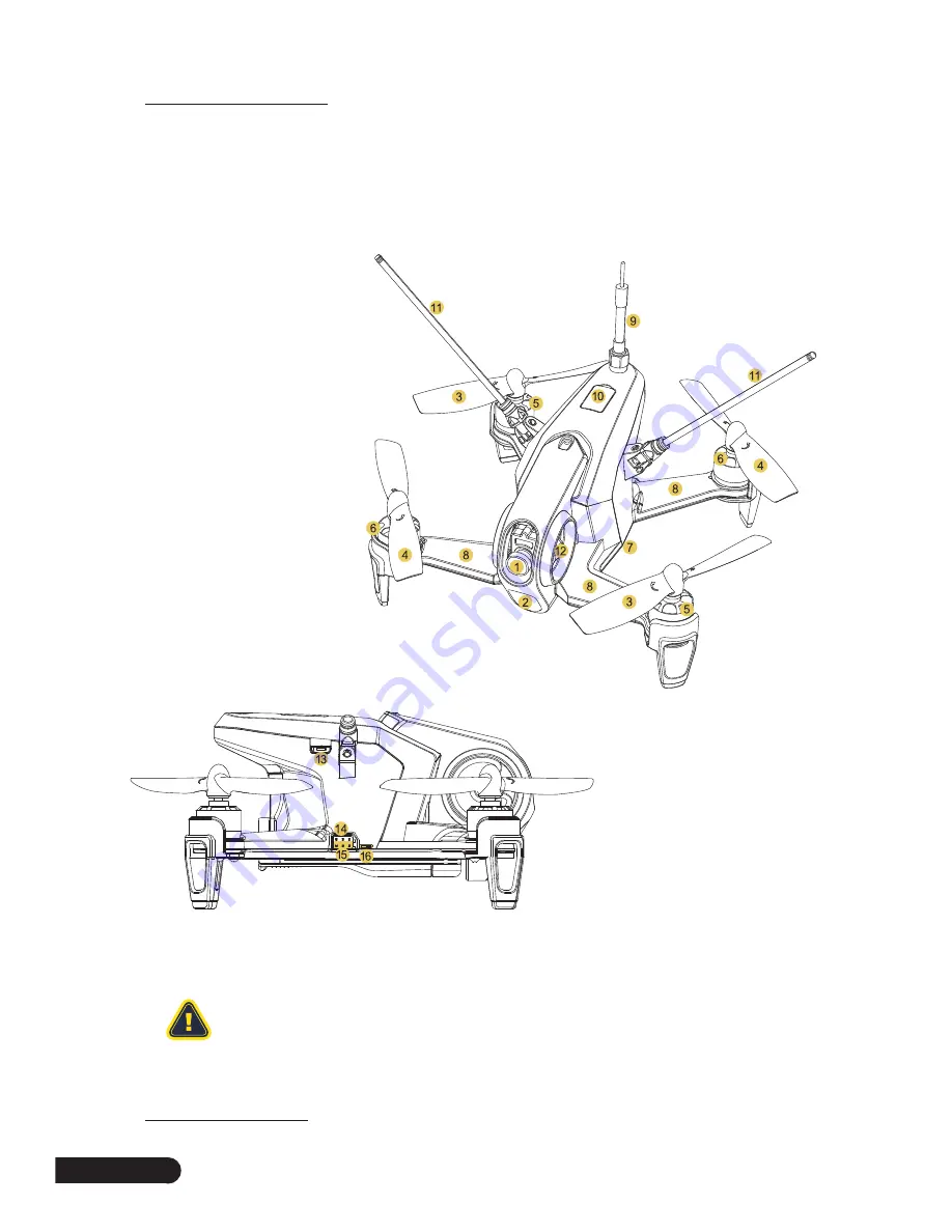
1. Camera
2. Headlight
3. Propeller (CW)
4. Propeller (CCW)
5. Clockwise Motor 

(Levogyrate thread is counterclockwise)

6. Counterclockwise Motor 

(Dextrogyrate thread is clockwise)

13. Main Flight Controller Upgrade Port
14. External Receiver Connection Port
15. 5V Power Output Port
16. Receiver Toggle Switch (PPM & SBUS)

7. Li-Po Battery 
8. Brushless ESC
9. 5.8G Transmitter Antenna
10. Code Switch
11. Receiver Antennas
12. Red LED Light

Summary of Contents for SWAGDRONE 150-UP

Page 1: ...QUICK START GUIDE SAVE THIS GUIDE FOR FUTURE USE www SWAGTRON com 150 UP ...

Page 2: ... all new ways to take your swag to new heights To ensure your safety and the safety of others please read and be sure to follow all instructions and safety recommendations in this User Manual prior to and when flying your SwagDrone If you have any questions regarding the SwagDrone contact us at 1 844 299 0625 for further assistance Happy Flying The SWAGTRON Team ...

Page 3: ...rol 10 9 0 Landing 12 10 0 Additional Instructions 12 10 1 Remote Controller Settings 12 10 2 Receiver Introduction 13 10 3 Video Transmitter Channel Selection 14 10 4 Introduction for Main Flight Controller 14 10 5 Power Board Overview 15 10 6 Connection Diagram of Brushless ESC Brushless Motor 15 11 0 GA005 Balance Charger 16 12 0 Warnings Information 17 12 1 Safety Warnings 17 12 2 Disposal at ...

Page 4: ...s guide in its entirety before attempting to use the SwagDrone 150 UP Always extend the Receiver Antennas before flight 2 0 Remote Control 1 Camera 2 Headlight 3 Propeller CW 4 Propeller CCW 5 Clockwise Motor Levogyrate thread is counterclockwise 6 Counterclockwise Motor Dextrogyrate thread is clockwise 13 Main Flight Controller Upgrade Port 14 External Receiver Connection Port 15 5V Power Output ...

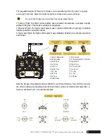
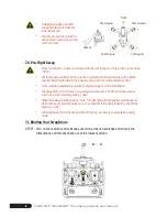
Page 5: ...ight control system uses stabilizes flexibility for advanced operation and rollover Note the images and examples below of MODE 2 Left hand throttle The Left Stick controls the drone s altitude and heading while the Right Stick controls its directional movements i e forward backward left and right movements Up Down Forward Backward Left Turn Right Turn Right Inclination Left Inclination Left Stick ...

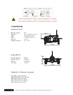
Page 6: ...n the left SwagDrone 150 UP Main Rotor Diameter Dimensions Weight Battery Flight Time Working Temperature 96mm 137 L x 148 W x 77 H mm 159g Battery excluded 7 4V 850mAh 25C 2S LiPo 7 8mins 14 F 104 F 5 8G Wireless Image Transmission TX5832 FCC Bind B Section 8 Channels TX5833 CE B Section 8 Channels TX5832 FCC Output Power 200mW TX5833 CE Output Power 25mW Horizontal Resolution System Committee Vi...

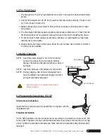
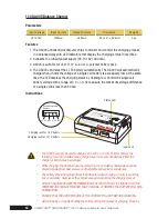
Page 7: ...ldren or within sports stadiums 5 0 Battery Charging STEP1 Insert the power adapter 100 240V 50 60Hz connect the output end to the GA005 balance charger the balance charger will show a solid red LED light STEP2 Insert the balanced LiPO battery pin into GA005 STEP3 During charging Red LED will continually flash Once the battery has been fully charged the Red LED light will flash solid green Refer t...

Page 8: ...ol Video receiving equipment is needed to display image and OSD information The SwagDrone 150 UP uses a low voltage alarm beeper The OSD provides a visual reference for the remaining battery power When the voltage reaches below 7 volts the right LED will flash quickly and the beeper alarm will sound Land the drone as soon as possible if the alarm is heard or the OSD is showing 7 volts The SwagDron...

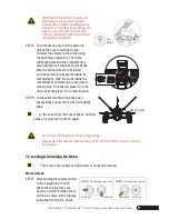
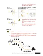
Page 9: ...cords inside the compartment and slide the cover closed making sure it s locked in place Turn the drone over and place it on a level surface STEP3 In the event that the drone has been successfully bound the red LED will slowly blink In the event that the buzzer keeps buzzing please try binding the drone again Do not move the SwagDrone 150 Up during binding Always extend the Receiver Antennas befor...

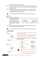
Page 10: ...he stick up a little the motors should start Motor Lock STEP1 Gently move the RUDD Stick to the right side push the THRO Stick down and hold on for more than two seconds On Mode 2 the THRO throttle and RUDD rudder is on the same stick STEP2 When the motor locks the red LED light will turn on and the buzzer will issue a sound indicating that the motors are locked You can test this by pushing the st...

Page 11: ...lines Be aware of your surroundings at all times flips it is highly recommended that you gain an appropriate amount of altitude first Ensure that the MIX switch is in position 1 or 2 for Mid level or High level Flight modes Always select large open spaces with soft ground for flying Rolls and flips are best suited for experienced pilots In the event that you do wish to perform rolls and flips it i...

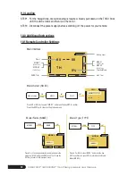
Page 12: ...el RUDD Trim Timer AILE Trim Throttle Model 00 00 TH 0 Main Interface UP DN MODEL NAME ENT MODEL 0 1 R150 Model Name NAME Press R or L to change characters and digits name the model as R150 and press ENT to confirm Press the EXT Key to return to the previous menu UP DN MODEL TYPE ENT MODEL HELI AERO Press UP or DN to select AERO and press the key ENT to confirm and press EXT to return back to Mode...

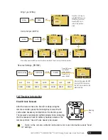
Page 13: ... UP R L DN R L DN R L MODEL OUTPU MODEL GEAR MIX MODEL GEAR ACT MODEL FLAP ACT MODEL FLAP FMD MODEL AUX2 GEAR MODEL AUX2 ACT DN R L Device Output OUTPU After setting press the ENT Key to confirm then press the EXT Key to return to the Main Interface UP DN MODEL WING ENT MODEL WING NORM Wing Type WING Press the L or R keys to select NORM and press the ENT key to confirm Press the EXT Key to return ...

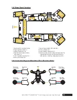
Page 14: ...ver channel 10 4 Introduction for Main Flight Controller Flexible Flat Cable Connection Port Introduction 1 4 Pin Port Not used 2 6 Pin Port Not used 3 Data Port Used for upgrading 4 Connection Port Used for connection to the flexible flat cable O N 3 2 1 O N 3 2 1 O N 3 2 1 O N 3 2 1 O N 3 2 1 O N 3 2 1 O N 3 2 1 O N 3 2 1 1 5866MHz CE 5847MHz FCC 5847MHz 5828MHz 5809MHz 5790MHz 5771MHz 5752MHz 5...

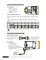
Page 15: ...he battery voltage dips below 7 0V 1 Brushless ESC Connection Position 2 Signal Light Connection Port 3 Headlight Connection Port 4 Main Controller Flexible Flat Cable Connection Port 5 5 8G Transmitter Connection Port 6 Receiver Connection Port 10 5 Power Board Overview 10 6 Connection Diagram of Brushless ESC Brushless Motor Front Brushless ESC Brushless ESC Brushless ESC Brushless motor CCW Bru...

Page 16: ... more sets of batteries Either the charger or battery may be damaged While charging the GA005 should be placed in a dry and well ventilated place and be placed far away from heat sources and flammable and explosive substances The battery should be removed from the helicopter when charging In order to avoid the risk of accidents never leave the charger unsupervised during the charging process DO NO...

Page 17: ...of significant heat or combustible materials This product is for outdoor use only Properly dispose of all packaging material Some items may be packed in plastic bags or material and may cause suffocation or injury to pets or children Do not place heavy weight on the product or any of its accessories Do not place anything inside the product other than battery as described in this manual Do not use ...

Page 18: ...rence does occur to radio or television reception which can be determined by turning the equipment off and on the user is encouraged to try to correct the interference by one or more of the following measures Reorient or relocate the receiving antenna Increase the separation between the equipment and the receiver Connect the equipment to an outlet on a circuit different from that to which the rece...

Page 19: ...e c improper use d failure to follow the product instructions or to perform any preventive maintenance e modifications f unauthorized repair g normal wear and tear or h external causes such as accidents abuse or other actions or events beyond our reasonable control Important Do not disassemble the Product Disassembling the Product will void this Warranty Only SWAGTRON or a party expressly authoriz...

Page 20: ......

Reviews: