background image

A Swagelok Pre-Engineered Subsystem        Fast Loop Module

24

Swagelok Tube Fitting Instructions
for 1 in. (25 mm) and smaller 

fittings 

Fig. 1

Fig. 2

Fig. 3

Fig. 4

Fig. 5

Fig. 6

Fig. 7

Installation


These instructions apply to both traditional 

fittings and to fittings with the advanced back-

ferrule geometry.
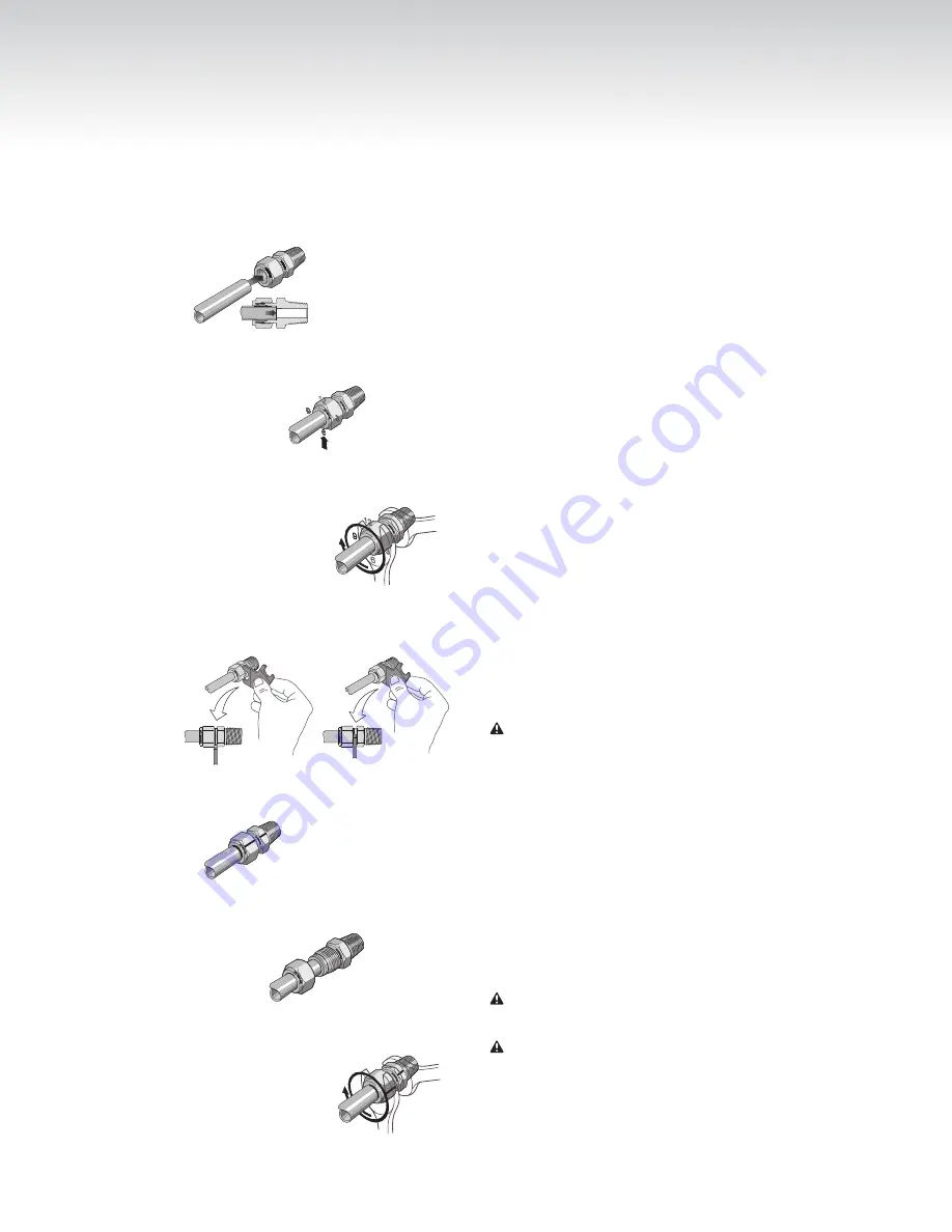
1.   Fully insert the tube into the fitting and 

against the shoulder; rotate the nut finger-

tight. 

Fig. 1

High-Pressure Applications and High 

Safety-Factor Systems:

 Further tighten the 

nut until the tube will not turn by hand or 

move axially in the fitting.

2.   Mark the nut at the 6 o’clock position. 

Fig. 2

.

3.   While holding the fitting body steady, tighten 

the nut one and one-quarter turns to the 

9 o’clock position. 

Fig. 3

.  

Note: For 

1/16, 1/8,

 and 

3/16 in.; 2, 3,


and 

4 mm

 tube fittings, tighten the nut 

three-quarters turn to the 3 o’clock position.

Gaugeability 

On initial installation, the Swagelok gap 

inspection gauge assures the installer or 

inspector that a fitting has been sufficiently 

tightened.
Position the Swagelok gap inspection gauge 

next to the gap between the nut and body. 

Fig. 4

.

•  If the gauge will not enter the gap, the fitting 

is sufficiently tightened.

•  If the gauge will enter the gap, additional 

tightening is required.

Reassembly Instructions 

— You may 

disassemble and reassemble Swagelok tube 

fittings many times.

   Warning 

Always depressurize the system before 

disassembling a Swagelok tube fitting. 

1.   Prior to disassembly, mark the tube at the 

back of the nut; mark a line along the nut 

and fitting body flats. 

Fig. 5

.

Use these marks to ensure you return the nut to 

the previously pulled-up position.

2.   Insert the tube with preswaged ferrules into 

the fitting body until the front ferrule seats 

against the fitting body. 

Fig. 6

.

3.   While holding the fitting body steady, rotate 

the nut with a wrench to the previously 

pulled-up position as indicated by the marks 

on the tube and the flats; at this point you 

will feel a significant increase in resistance. 

Fig. 7

.

4.   Tighten the nut slightly. 

   Caution 

Do not use the gap inspection gauge 

with reassembled fittings.

   Caution 

Do not mix or interchange parts with 

those of other manufacturers.

For additional information, see the 

Gaugeable 

Tube Fittings and Adapter Fittings

 catalog, 

MS-01-140.

Summary of Contents for Fast Loop Module

Page 1: ...lok Pre Engineered Subsystem Pre engineered subsystems available in weeks not months Field tested design ensures optimum system performance A Swagelok Pre Engineered Subsystem User s Manual Fast Loop...

Page 2: ...alves MS INS 40 27 Packing Adjustment for 40G Series Ball Valves MS INS 40G 28 R3A Series Externally Adjustable Relief Valve Maintenance Instructions MS CRD 0013 29 R4 Series Relief Valve Maintenance...

Page 3: ...Fast Loop Module FLM System Manual Configuration 4 1 2 in Liquid System with Optional Grab Sample and Relief Outlets Shown A Swagelok Pre Engineered Subsystem Fast Loop Module 3...

Page 4: ...ge gas for system cleaning The FLM extracts a sample through a filter while using the high flow rate of the fast loop to keep the filter element clean All FLM subsystems feature dual interlocked ball...

Page 5: ...NV FI FFL Filter fast loop FP FM FC NV1 FI PSV C CV SHV V FFL SN PV NV FI NV Needle valve grab sample or purge outlet PR FP BV BV PI RV FM FP FM FC MV NV1 NV FI PSV C CV SHV SSV FFL SN PV NV FI NV Ne...

Page 6: ...NV1 NV1 NV2 FFL SN RV FI C C Fast Loop Out Fast Loop In To Analyzer Liquid Gas Liquid Grab Sample Outlet Relief Outlet Needle valve NV1 Ball valve BV1 BV2 Relief valve RV Pressure indicator PI Grab s...

Page 7: ...V C C FI Fast Loop Out Fast Loop In To Analyzer From Analyzer Liquid Liquid Gas Needle valve NV1 Ball valve BV1 BV2 Pressure indicator PI Grab sample needle valve NV2 Flow indicator FI Filter FFL Reli...

Page 8: ...Fast Loop Out Fast Loop In To Analyzer Oily Drain Vent Oily Drain Vent From Analyzer Liquid Liquid Gas Needle valve NV1 Ball valve BV1 BV2 Ball valve BV3 BV4 Plug valve PV Pressure indicator PI Grab s...

Page 9: ...In To Analyzer Oily Drain Vent Purge Oily Drain Vent From Analyzer Liquid Liquid Gas Needle valve NV1 Ball valve BV1 BV2 Ball valve BV3 BV4 Plug valve PV Pressure indicator PI Grab sample needle valve...

Page 10: ...e outputs to the analyzer on the right System operation is not recommended in any other orientation Dimensions in inches centimeters are for reference only and are subject to change Top 7 50 19 0 1 50...

Page 11: ...Right Side Fast loop inlet Fast loop outlet Relief outlet option 5 94 15 1 1 81 4 60 16 2 41 1 13 8 35 1 1 09 2 77 6 70 17 0 18 7 47 5 8 10 20 6 9 39 23 9 10 7 27 2 0 88 2 24 Return from analyzer Out...

Page 12: ...ple conditioning system prior to the analyzer 3 Return from Analyzer option connect to the outlet line from the analyzer There must be sufficient pressure to create flow back into the FLM return 4 Pur...

Page 13: ...moving the black handle BV1 BV2 to the left 2 Configurations 3 and 4 Close the sample return valve by moving the red handle BV3 BV4 to the up position 3 Open flow to the FLM by opening all fast loop...

Page 14: ...4 in R3A Series Externally Adjustable Relief Valve Maintenance Instructions page 29 1 2 in R4 Series Relief Valve Maintenance Instructions page 36 Note 1 2 in systems with perfluorcarbon FFKM seals wi...

Page 15: ...le to the down position to switch the analyzer return line to drain mode and opens the purge lines Purge lines are in Configuration 4 only 5 Configuration 4 To adjust purge flow turn the handle of the...

Page 16: ...purge valve PV 5 Configurations 4 After a suggested minimum of five minutes close the purge line by moving the red handle to the up position 6 Verify that the FLM is depressurized by checking the pre...

Page 17: ...just the valve packing according to 1 4 in Packing Adjustment Card for 40G Series Ball Valves page 28 1 2 in Packing Adjustment Card for 40 Series Ball Valves page 27 9 Configurations 3 and 4 To adjus...

Page 18: ...tem according to VCO Fittings Installation Instructions page 25 Verify that the O ring is in place when reassembling the fitting The locations of the VCO fittings within a Configuration 4 FLM are indi...

Page 19: ...outlet 3N series Flow indicator 1 4 in FLM M1 series 1 2 in FLM M3 series Variable Area Flowmeters G Series and M Series MS 02 346 Ball valve 40G or 40 series One Piece Instrumentation Ball Valves 40...

Page 20: ...re in the process pipe near the sampling nozzle If flow rate is acceptable there may be a partial blockage in probe or sample transport lines to the FLM Partially close the needle valve NV1 and check...

Page 21: ...lvent to remove oil and solid deposits Remove the flowmeter and clean the inside of the flow tube Replace the flowmeter One of the bypass valves is not fully closed Move the black handle to the right...

Page 22: ...nstalling a larger size tube or pipe for sample return line to process Consider changing the method of disposing of the analyzed sample There is high flow resistance in the sample path to the analyzer...

Page 23: ...e is backflow into the analyzer Check valve CV1 is stuck open Maintain or replace the check valve Verify orientation when the check valve is reinstalled Pressure indicator PI pointer is vibrating exce...

Page 24: ...inspection gauge next to the gap between the nut and body Fig 4 If the gauge will not enter the gap the fitting is sufficiently tightened If the gauge will enter the gap additional tightening is requi...

Page 25: ...6 Finger tight Swagelok VCO Fittings Installation Instructions Bodies without weld fittings 7 45 GTAW 4 5 3 1 4 in 6 mm 2 1 16 1 8 3 16 in 2 3 4 mm 1 2 4 5 6 7 11 10 9 8 12 3 A Swagelok Pre Engineered...

Page 26: ...1 4 5 9 Bodies with weld fittings 8 Finger tight 45 GTAW 3 GTAW 2 6 7 Swagelok VCO Fittings Installation Instructions A Swagelok Pre Engineered Subsystem Fast Loop Module 26...

Page 27: ...y be required during the service life of the valve to prevent leakage Before servicing any installed valve you must depressurize the system cycle the valve and purge the valve Adjust the packing by tu...

Page 28: ...uring the service life of the valve to prevent leakage Adjusting the Packing 1 Adjust the packing by turning the packing bolt clockwise in 1 16 turn increments until leak tight performance is achieved...

Page 29: ...rque wrench capable of 10 in lb 1 1 N m Set screw 100 in lb 11 3 N m Lock nut Pic n a O rings Spring Kit Spring Label Lockwire Spring Designator and Color Set Pressure Range psig bar Initial Cap Posit...

Page 30: ...Loosen Cap Bonnet Discard Lubricate WARNING Before servicing any installed valve you must depressurize system cycle valve purge the valve WARNING Residual material may be left in the valve and system...

Page 31: ...pressure 14 15 Lock nut Cap Tighten against cap Lock nut Tighten to 100 in lb 11 3 N m Body Lockwire Cap Lead seal 1 Follow steps 1 through 4 in the Spring Installation section Springs A B or C can be...

Page 32: ...ction Pull rod Handle Thread onto pull rod Set screw Tighten to 10 in lb 1 1 N m Cap Thread to initial position indicated in Spring Kit Identification table R3A Series Externally Adjustable Relief Val...

Page 33: ...iner Bonnet O ring WARNING Before removing any installed valve you must depressurize system cycle valve purge valve WARNING Residual material may be left in the valve and system CAUTION Do not scratch...

Page 34: ...rt Seat O ring Insert 11 12 13 14 Insert assembly Seat retainer Tighten to 250 in lb 28 2 N m Seat retainer Teeth facing away from quad seal Quad seal Retainer Stem Lubricate top of stem R3A Series Ex...

Page 35: ...at retainer Seat O ring Insert Lock wire hole Swagelok proportional relief valves should never be used as code safety relief valves Some system applications require relief valves to meet specific safe...

Page 36: ...valve in system Grip valve on wrench pad during installation Spring Kit Identification Spring Kit Ordering Number Color Code Nominal Cracking Pressure psig bar Initial Cap Position number of turns 177...

Page 37: ...p to 100 in lb 11 N m Plug Cap Spring Label Lock Wire Hole Lock Nut Spring Support Bearing Bonnet Lock Wire Hole Body 10 Lock wire the cap and body together to maintain relief setting Manual Override...

Page 38: ...ht down into body See Fig 3 Note Do not pinch O rings between body and plug 5 Install snap ring with snap ring pliers or similar tool See Fig 4 6 Test the valve for proper operation Large O rings Smal...

Page 39: ...o the bonnet on top of the packing Place the gland into the bonnet Proceed to step 10 9b UHMWPE Packing Lubricate the stem threads with MS LT NNS 1 and re insert the stem through the bottom of the bon...

Page 40: ...w into the bonnet 11 Lubricate the top 2 or 3 threads on the bonnet and screw lock nut onto the bonnet 12 Place the handle on the stem Be certain that the set screw hole is aligned with the indentatio...

Page 41: ...s procedure is shown with Swagelok Tube Fitting end connections These instructions also apply to check valves with pipe ends and check valves with VCR and VCO ends Component Identification End Connect...

Page 42: ...pressure 3 Test the valve to ensure it stops reverse flow Testing Nominal End Connection Size Tool Size and Quantity Wrenches Socket for body Hex Qty 2 for End Connection Qty 1 for body Hex Qty 1 1 8...

Page 43: ...n the outlet body 3 Slide the O ring over the threads against the backup ring 4 Insert the spring into the body 5 Lubricate the body threads with a system compatible lubricant 2 Lubricate the O ring w...

Page 44: ...assembly The O ring must fit tightly into the inlet body 9 Look into the valve outlet port to verify that the spring is aligned in the center of the poppet stop 10 Tighten the valve bodies 11 Refer t...

Page 45: ...e a backup wrench End connection leakage Inspet end connection for damage replace if damaged Reinstall the fitting to the valve end connection Contamination on body O ring 4 Clean O ring and reassembl...

Page 46: ...responsibilities of the system designer and user Caution Do not mix or interchange parts with those of other manufacturers Poppet O ring Good Contaminated Ref 1 Swollen Ref 2 Damaged Ref 3 Good Conta...

Page 47: ...Tornado Model 601 Element Replacement Kit Instructions Element Kit Part 601 5TX A Swagelok Pre Engineered Subsystem Fast Loop Module 47...

Page 48: ...Tornado Model 601 Element Replacement Kit Instructions Element Kit Part 601 5TX A Swagelok Pre Engineered Subsystem Fast Loop Module 48...

Page 49: ...Tornado Model 601 Element Replacement Kit Instructions Element Kit Part 601 6XX A Swagelok Pre Engineered Subsystem Fast Loop Module 49...

Page 50: ...Tornado Model 601 Element Replacement Kit Instructions Element Kit Part 601 6XX A Swagelok Pre Engineered Subsystem Fast Loop Module 50...

Page 51: ...Tornado Model 602 Maintenance Instructions A Swagelok Pre Engineered Subsystem Fast Loop Module 51...

Page 52: ...Tornado Model 602 Maintenance Instructions A Swagelok Pre Engineered Subsystem Fast Loop Module 52...

Page 53: ...Tornado Model 602 Maintenance Instructions A Swagelok Pre Engineered Subsystem Fast Loop Module 53...

Page 54: ...Tornado Model 602 Maintenance Instructions A Swagelok Pre Engineered Subsystem Fast Loop Module 54...

Page 55: ...A Swagelok Pre Engineered Subsystem Fast Loop Module 55...

Page 56: ...foil TM GrafTech International Holdings Inc 2011 2019 Swagelok Company MS 13 219 RevB April 2019 Warranty Information Swagelok products are backed by The Swagelok Limited Lifetime Warranty For a copy...

Reviews: