background image

SV 104 USER'S MANUAL_

DRAFT

_______________________________________________ 

71 

INDEX 

Accessories available · 14 
Accessories included · 14 
Applications · 11 

Basic configuration · 32 
Battery check · 30 

Calibration · 33 
Charging · 27 
Cleaning · 67 
Control of the instrument · 19 

Dosimetry · 9 

Enter · 19, 21, 49 

Firmware update · 68 

Icons · 18 
In situ calibration · 67 
Instrument status view mode · 26 

Kit components · 13 

Led status indicator · 18 

Measurement procedures · 12 
Measurement setups · 32 
Mounting · 38 
Mounting clips · 17 

Periodic testing · 67 
Positioning · 38 
Primary parameters view mode · 24 
Profile · 19, 21 

Resetting the dosimeter · 39 
Results list view mode · 24 
Running spl view mode · 23 

Scroll · 19, 21, 49 
Security lock · 38 
Service · 70 
Software options · 14 
Sound pressure · 9 
Standards · 10 
Starting and stopping measurement run · 37 

Unit name · 31 

Vibration marker · 53 
View mode · 23 
Voice comments · 36 

Windshield · 17 

IIIInnnnstrstru

stru

struument

menta

menta

mentaation for Science 

tion for Science a

tion for Science a

tion for Science aannnndddd  I

 I

 IInnnndddduuuusssstrytrytrytry


ISI sa-nv Rue du Doyenné 3 - 1180 Brussels  Tel +32 (0) 2 343 30 81 Fax 02/ 343 12 05 web : http:// 

www.isi-be.com 


mail : [email protected]

Summary of Contents for SV 104

Page 1: ...ARSAW July 2013 I I I In n n nstr stru stru stru ument menta menta menta ation for Science tion for Science a tion for Science a tion for Science a an n n nd d d d I I I In n n nd d d du u u us ss stry try try try ISI sa nv Rue du Doyenné 3 1180 Brussels Tel 32 0 2 343 30 81 Fax 02 343 12 05 web http www isi be com mail sales isi be com ...

Page 2: ...eserves the right to make changes to product specifications without notice To download the most up to date user s manual please visit our web site at www svantek com This user s manual presents the firmware revision named 1 02 01 see the Unit Label review chapter 4 5 to check version details This user s manual presents some aspects of SUPERVISOR software revision named 1 0 7 see the software start...

Page 3: ...s indicator 18 3 6 Status bar icons 18 3 7 Manual control of the instrument 19 3 7 1 Primary key functions 20 3 7 2 Alternate key functions 21 3 7 3 Alternate combined keys function 22 3 8 Three instruments in one ACOUSTIC PROFILE concept 23 3 9 The VIEW mode presentation concept 23 3 9 1 Running SPL view mode 23 3 9 2 Primary ONE RESULT parameters view mode 24 3 9 3 RESULTS LIST view mode 24 3 9 ...

Page 4: ...ta logging settings tab 48 5 4 5 Display VIEW configuration tab 49 5 4 6 Octave analysis Spectrum configuration tab 50 5 4 7 General settings tab 50 5 4 7 1 Calibration settings panel 51 5 4 7 2 Statistical levels settings panel 51 5 4 7 3 Security settings panel 52 5 4 7 4 Auxiliary settings panel 53 5 4 8 Auto Run settings timer pauses tab 54 5 4 9 Recording options tab 56 5 4 9 1 Event and Wave...

Page 5: ...SV 104 USER S MANUAL_DRAFT_______________________________________________ _ 5 7 SVANTEK SERVICE 70 ...

Page 6: ...IGURE 4 8 CALIBRATION INITIAL DELAY SCREEN 34 FIGURE 4 9 CALIBRATION IN PROGRESS SCREEN 34 FIGURE 4 10 CALIBRATION CONFIRMATION SCREEN 34 FIGURE 4 11 CALIBRATION MICROPHONE NOT IN TOLERANCE SCREEN 35 FIGURE 4 12 VOICE COMMENT LINKING SCREEN 36 FIGURE 4 13 VOICE COMMENT RECORDING COMMAND SCREEN 36 FIGURE 4 14 VOICE COMMENT RECORDING IN PROGRESS SCREENS 36 FIGURE 4 15 VOICE COMMENT RECORD CONFIRMATI...

Page 7: ...TRUMENT CONFIGURATION PANEL 62 FIGURE 5 28 LOGGER 1 1 OCTAVE PANEL 63 FIGURE 5 29 LOGGER 1 1 OCTAVE TSECT PANEL 63 FIGURE 5 30 LOGGER COMBINED PANEL 63 FIGURE 5 31 LOGGER RESULTS PANEL 64 FIGURE 5 32 LOGGER STATISTICS PANEL 64 FIGURE 5 33 MARKED PERIODS TOTALS PANEL 65 FIGURE 5 34 NOISE EXPOSURE ISO 9612 PANELS 65 FIGURE 5 35 SESSION HEADER PANEL 66 FIGURE 5 36 CONFIGURABLE TEXT PANEL 66 FIGURE 5 ...

Page 8: ...mputational power of its digital signal processor the SV 104 instrument can simultaneously measure the dosimeter results and perform real time 1 1 Octave analysis including the calculations of the statistical levels An inbuilt tri axial accelerometer for vibration shock detection firmly places SV 104 as both the most technically advanced and the most robust personal dosimeter out there Advanced ti...

Page 9: ...nated or controlled it may cause permanent hearing loss in workers The so called inner ear is very fragile part of our hearing sense which with current knowledge in medicine cannot be truly repaired Therefore it is of great importance to protect our senses from excessive noise Exposure to high levels of noise may also create physical and psychological stress reduce productivity and interfere with ...

Page 10: ...orkers to the risks arising from physical agents noise or International Electrotechnical Commission IEC 61252 guidelines The EU directive links to the ISO 9612 2009 Acoustics Determination of occupational noise exposure Engineering method In the United States the Occupational Safety and Health Administration OSHA 29 Code of Federal Regulations CFR 1910 General Industry Regulations Standard No 1910...

Page 11: ...meters at regular intervals and superimposed random vibration shock or audio events during a run Noise profiled results can be easily transferred to the Supervisor or SvanPC software packages The noisiest times can be immediately seen in the graphical report and actions directed to the appropriate area This makes checking for different regulatory bodies compliance and ensuring if hearing conservat...

Page 12: ...d be as follows 1 Check that the indicated instrument battery life is at least twice the time required for the measuring period 2 Check the instrument setup mode is appropriate and change if necessary 3 Check the calibration of the instrument and adjust the settings if required 4 Secure the instrument onto the shoulder of the employee selected for sampling Refer to the chapter with specific requir...

Page 13: ... use predefined setups Time history data logging of Leq Lav Lmax Lmin Lpeak with variable 0 1 s to 1 hr logger step and separate summary results intervals with statistical levels 1 1 Octave real time analysis 9 filters with centre frequencies 31 Hz 8 kHz Type 2 IEC 1260 presented as a bar graph with Leq and Lmax band levels plus overall A C and Z broadband weightings as option called SF 104 OCT Au...

Page 14: ...B SC 156 micro USB 2 0 cable SA 54 Charger power supply for 1 x SV 104 SA 73 Carrying case for 5 x SV 104 dosimeters and accessories waterproof SA 156 USB HUB for charging and data download from 5 x SV104 dosimeters Supervisor Software for configuration viewing and exporting data USB drivers MS Windows XP Vista Windows 7 for 32 and 64 bit operating systems available as freeware 2 4 Instrument Soft...

Page 15: ...n The following Figure 3 1 shows the SV 104 controls and ports Figure 3 1 SV 104 at a glance Colour display 128 x 64 pixel resolution LED status indicator AMBER stop mode GREEN measuring RED alarm SV 27 microphone with SA 122 windshield Mounting accessories suspender clips Keypad Three control keys SCROLL PROFILE ENTER ...

Page 16: ...one connector essential for measuring micro USB connector charging and data download charging connector reserved for future use fast infrared port reserved for future use Figure 3 2 SV 104 side view microphone and micro USB connector Figure 3 3 SV 104 back view charging and infrared port reserved for future use infrared port charging connector micro USB connector microphone mounting head ...

Page 17: ...nts The SV 104 uses an innovative windshield magnetic technique to fit tightly onto the microphone housing To remove the windshield just put more force holding the lower half of the foam and lift the windshield off the microphone housing Once the SV 104 has been calibrated refit the windshield by carefully placing it back over the microphone again Figure 3 4 SA 122 windshield 3 4 The mounting clip...

Page 18: ...lashes with a duration of nominally one second Indicates vibration shock threshold has been detected This will go off once the high vibration shock has ceased RED flashing quickly four times per second Indicates the alarm conditions for instance the dose has exceeded the alarm level Table 3 1 LED status description 3 6 Status bar icons The upper part of the display is designed as basic status info...

Page 19: ...rate the instrument by change the VIEW 2 mode with the ENTER key select the required ACOUSTIC PROFILE 3 with the PROFILE key and SCROLL thru the results with the SCROLL key Notice To save power consumption and extend battery life SV 104 will automatically switch off the display after 30 seconds if no button on the keypad is pressed The LED indicator will still inform the user about the current sta...

Page 20: ...llowing control push buttons are located See below for primary short press key functions description Figure 3 7 Control keypad on the front panel primary key functions PROFILE key change presented ACOUSTIC PROFILE 1 2 3 1 etc SCROLL key scroll down thru RESULTS ENTER key Change VIEW mode see chapter 3 9 ACOUSTIC PROFILE number and status bar RESULTS ...

Page 21: ...igure 3 8 Control keypad on the front panel alternate key functions Holding down individual key for few seconds during which a countdown is displayed the SV 104 gives you time to decide if you really want to access the function that is going to be executed Shutting down 3 2 1 for the ENTER key Keyboard lock 3 2 1 for the SCROLL key Voice comment 3 2 1 for the PROFILE key If you release the key too...

Page 22: ...en more functionalities Figure 3 9 Control keypad on the front panel alternate combined keys function Notice Extra additional keypad functionality is also available to display the instrument s Unit Label screen showing the current firmware revision number It is accessible by a short press of all three keys at once PROFILE ENTER Enter Exit CALIBRATION SCROLL ENTER Enter Exit predefined SETUP LOADER...

Page 23: ... and status information will be presented in different manner as distinct screen content SV104 features the following VIEW modes where most of them can be individually disabled Running instantaneous SPL view mode 3 9 1 can be disabled with PC software Primary one result parameters view mode 3 9 2 cannot be disabled Results list view mode 3 9 3 can be disabled with PC software Octave analysis spect...

Page 24: ...irment Figure 3 11 Primary parameters view mode screen 3 9 3 RESULTS LIST view mode To get information about a number of results at one time it is handy to switch to the results list view mode Up to three parameters at a time are accessible for the operator Figure 3 12 Results list view mode screens acronym for weighting filter A C Z detector type Fast Slow Impulse measured parameter name acoustic...

Page 25: ...e settings of the level meters for profiles The spectra are always linearly averaged Thus the TOTAL values from 1 1 octave band analysis can be different from those obtained for the profiles if the LEQ Integration was set as Exponential The results of 1 1 Octave analysis so called spectrum can be examined by the user on a display in Spectrum VIEW presentation mode 1 1 Octave spectra for all 9 cent...

Page 26: ... 5 there are a few alarm conditions when ALARM presentation screens will appear During a measurement run the SV 104 will immediately turn on the display at the time that the programmable alarm condition is exceeded The detailed alarm state condition for each profile is presented to the user Press any key to confirm the information Figure 3 16 Alarm view screens Notice At any time when battery powe...

Page 27: ...is prevents damage to the batteries The number of hours you have used your dosimeter from your last charge will impact your total charge time For example if the battery clock indicator displays 40 hours remaining on the battery and you wish to charge the battery the approximate charging time is 1 hour Notice To charge a fully discharged battery it would take approximately 1 5 to 2 5 hours Note als...

Page 28: ...ine during this time the manufacturer s logo the name of the instrument and firmware version is displayed Then the SV104 will run through a short start up sequence showing the current configuration setup loaded along with the names of all of three profiles followed by battery state screen After this the instrument will enter the stopped ready to measure mode and enter the running instantaneous SPL...

Page 29: ...dditional double check warning screen This is for the operator to be aware and convinced the unit is really to be turned off See figure below Figure 4 1 Power off warning screen Notice SV 104 will automatically shut down after 5 minutes in stopped ready to measure mode Notice If auto run timer mode is active SV 104 will automatically stop the measurement when the set time is over and then turn off...

Page 30: ... charge counter and should be considered only as an overall not very precise determined estimation Therefore the time left could be noticeably different Although the newest technology cells are used the slight degradation over time is inevitable thus aging requires occasionally factory based or authorised service centre replacement of the rechargeable battery cells Notice Battery power indicator T...

Page 31: ...o IEC 61252 2002 o ANSI S1 25 R2007 meaning ANSI S1 25 1991 R2007 o Type 2 IEC 61672 2002 o Type 1 IEC 61260 1995 meaning with Am1 2001 To access Unit Label screen short press all three keys SCROLL PROFILE and ENTER at the same time The following screen will be presented Figure 4 3 Unit label screens Unit label screen is moved with SCROLL PROFILE keys To exit the Unit Label screen just short press...

Page 32: ...h SCROLL or PROFILE key The following screen will appear that will allow you to confirm you really want to load the selected setup or cancel the selection and return to configuration setup list Figure 4 5 Load setup confirmation Press SCROLL key to cancel the setup loading or PROFILE key to confirm loading selected setup configuration Confirming the loading of configuration setup leads to the scre...

Page 33: ...se is usually sufficient for most regulations Notice The calibration factor is always added to the results in the Dose Meter or 1 1 Octave analysis mode Notice The manufacturer s recommended factory calibration interval is every 12 months for this instrument to be confident in its continuing accuracy and compliance with the international specifications Please contact your local SVANTEK distributor...

Page 34: ...tion procedure without saving the calibration factor press PROFILE and ENTER 7 It is recommended to repeat the calibration measurement a few times The obtained results should be almost the same with 0 1 dB difference The reasons for the unstable results are as follows the calibrator is not properly attached to the instrument there are external acoustic disturbances such as high noise levels close ...

Page 35: ...st calibration If enabled the post processing is performed automatically under acceptance of calibration measurement Notice If it is required to perform so called post calibration of the instrument In case the Post Calibration is pre programmed within configuration setup the SV 104 automatically adds the results to the previously saved files ...

Page 36: ...pressing the SCROLL or the PROFILE key the record command window will open Figure 4 13 Voice comment recording command screen Starting the recording by means of the PROFILE key flashing circle that indicates recording in progress will appear on the screen Figure 4 14 Voice comment recording in progress screens Further one can continue to record a comment about the measurement and press PROFILE key...

Page 37: ...topping measurement run START To start the measurements the user has to press the SCROLL and PROFILE keys at the same time The results of the measurement are displayed in the last used result s display view mode As an example one profile mode is displayed One profile mode is always available for most Functions of the instrument The results of the measurements can also be presented in other display...

Page 38: ... the key too early SV 104 returns to the last presented VIEW mode Unlocking SV 104 unit To unlock the unit one has to press the keys in the correct sequence The sequence is pre programmed in the configuration setup look the chapter 5 4 7 3 Note that in case the security sequence is configured via SUPERVISOR software the simple hold of PROFILE key for a couple of seconds during which a countdown Ke...

Page 39: ...he results and unlock the keypad see chapter 4 12 Notice After reviewing results remember to lock the keypad again in order to maintain the integrity of the measurement run by preventing uncontrolled access to the instrument 4 15 Resetting the dosimeter SYSTEM RESET internal software reset clears any setup configuration and brings back the default factory settings See Appendix A for remote control...

Page 40: ...lation we are ready to connect the SV 104 dosimeter Plug the USB cable into the computer Plug the opposite end of the cable micro USB into the dosimeter itself The SV 104 is powered and charged directly through the computer thus you do not need separate charger The dosimeter screen will be switched on automatically with current charging information only Turn on the dosimeter see chapter 4 3 long p...

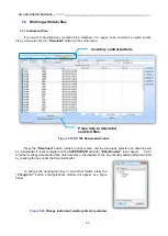
Page 41: ...l Data browser or Session you work with Instrument filter enables SV 104 device selection or other Health and Safety dedicated instruments Inventory panel detects all SV 104 connected devices see chapter 5 3 Quick access file manager enables you to copy configuration setup files between computer and instrument internal memory see chapter 5 4 1 Instrument configuration panel enables access to all m...

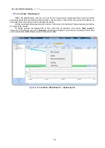
Page 42: ...d calibrator calibration report details Figure 5 3 Inventory panel and its capabilities There are two control buttons near the Inventory Panel top menu Settings button enables to configure current local configuration file that can be later uploaded to the SV 104 dosimeter Download button enables to navigate and download files directly from the dosimeter Notice To download any setup or data file fi...

Page 43: ...ument filter section The clicked instrument picture denotes that the models are selectable from inventory panel when setup changes are applied and the send setup to instruments is selected To gain access to settings window click the Settings button near the Inventory panel see chapter 5 3 5 4 1 Working with configuration setup files The idea behind the configuration setup is to download the config...

Page 44: ...n Supervisor window Figure 5 2 4 Go through all the tabs to verify or change required parameters of the measurement runs Follow the chapters from 5 4 2 to 5 4 9 to understand and configure the instrument 5 Once configured come back to setups file manager Figure 5 4 and click the just edited Settings in Local files panel 6 Next click the save button in bottom area of the panel Figure 5 4 7 To chang...

Page 45: ...u can enter the Load Setup menu directly in the instrument and load it as the current configuration See chapter 4 6 for details Figure 5 6 Instrument files panel and context commands 11 This ends the procedure Disconnect the dosimeter and the instrument is now ready for a new measurement run using the settings you have just uploaded Notice During configuration there are quite a number of parameter...

Page 46: ...lly greyed Others must be setup by the user There are three additional user defined presets whose name can be changed during configuration with use of the little icon notes with a pen which is then enabled Apart from alarm DOSE threshold there are three additional source of warning alarm which can be set See figure below Figure 5 7 Dosimeter settings profile configuration tab Notice Note that some...

Page 47: ...f operation the SV 104 should work Dosimeter or Dosimeter with 1 1 octave analysis Notice Enabling octave analysis shortens battery life so take it into consideration and double check the battery status before measurement run Other basic parameters configuration is per figure provided below Figure 5 8 Measurement configuration setttings tab select measurement mode of operation ...

Page 48: ...you want to log the parameters what name the logger file should have and if extended summary results should be saved Notice Summary results are saved on Integration Period basis not on Logger Step time See Figure 5 8 how to set Integration Period parameter Right panel named Results is accessible only if Logger switch button is set to On You have the ability to choose which basic results for each a...

Page 49: ...ce If you do not want to use all three ACOUSTIC PROFILES it would be convenient for you to enable only one acoustic PROFILE to be displayed just select the required one Notice The ONE RESULT chapter 3 9 2 is the only VIEW mode that is always present and cannot be disabled In the right panel named Display Results you will find a list of over a dozen measurement parameters that can be configured to ...

Page 50: ...panels named Data This configures the weighting filter that is to be used with octave calculation named Scale Here the visible dynamic range of the graphical plot can be set as well as the grid visibility enabled Figure 5 11 Spectrum configuration tab 5 4 7 General settings tab General settings tab concerns to many different usability options See the followed by chapters to understand exactly how ...

Page 51: ...f save in the last file Last File or save in the files which will be created after last calibration Files after last calibration Auto calibration can be disabled if required for any reason Figure 5 13 Calibration settings panel 5 4 7 2 Statistical levels settings panel In the Statistical Level panel it is possible to define ten percentile statistical levels named from N1 to N10 The default statist...

Page 52: ...d every time the measurement run is started See the chapter 4 12 how to lock and unlock the SV 104 instrument If Unlock on Key is set to On SV 104 will require special code to be input by pressing four keys defined in this panel in a particular sequence If Unlock on Key is set to Off SV 104 can be locked unlocked without providing Lock Unlock sequence Simply hold the PROFILE key for a couple of se...

Page 53: ...onfirmation just before switching off see chapter 4 3 Comment file name defines the name of the Voice note comment file Comment Text is also able to be entered here if required Vibration Marker is used on the basis of acceleration threshold setting Off 1g 15g the lower the threshold level selected then the more sensitive the dosimeter will be to possible bumps and shocks during use Language enable...

Page 54: ...gured in right panel named Timer can be switched off Off switched on only once Single or switched on many times on regular basis Regular Multiple times with the period between two consecutive measurements set in the Repetition line In the Simple instrument interface mode the Timer position doesn t appear in the Measurement list Selecting the mode of the timer function The timer can be switched off...

Page 55: ...e Real Time Clock is taken into account The required date can be selected Make sure to check that the real time clock settings for the measurement location are correct before beginning a delayed timer measurement Selecting the period between two consecutive measurements The Repetitions Number position is displayed when Regular mode is selected This parameter can be programmed from 1 up to 100 The ...

Page 56: ... are mutually exclusive functions and as such you need to turn off the one option in order enable the other one 5 4 9 1 Event and Wave recording configuration panel Audio Event and Wave Recording may be configured to measure in different Recording Mode See figure below Figure 5 18 Audio Event and Wave recording configuration panels ...

Page 57: ... bottom area and the previously selected run data files will be downloaded to local computer and the SUPERVISOR will enter Data Browser see chapter 5 5 2 to further manage downloaded files Run data files in the instrument can be optionally deleted after download by checking the box under the Download button To change the working directory or scan other folders press the Change dir button and appro...

Page 58: ...operator an initial idea of the time history of the measurement results All files are simply divided per specific function In the case of a dosimeter Noise dosimetry and Wave are relevant file groups To further process the selected file or files right click on selection and choose New session command This will bring you to the Session window see chapter 5 6 where the reporting tool will allow you ...

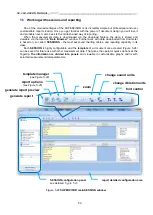
Page 59: ...loaded from dosimeter is based on so called SESSIONS the most advanced charting tables and reporting capability in its class Each SESSION is highly configurable and the template of a document once created Figure 5 24 can be saved for future use with other measurement data That gives the operator quick solutions at the fingertip The information is divided into panels and viewable in customizable gr...

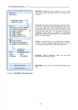
Page 60: ...panel can be added more than once It is possible to change the information in each panel for example one panel with parameters sorted in a table layout and the other with a graph or a zoomed graph Panels contains the list of currently added information chunks to the report detailed configuration area Here you can change the names of the individual added panels Reports contains information about us...

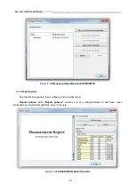
Page 61: ...anaging templates with SUPERVISOR 5 6 1 Report panels See the following panels then configure and generate report Report options With Report options window it is very straightforward to edit basic report information and predefined graphics colour and style Figure 5 25 SUPERVISOR Report Options ...

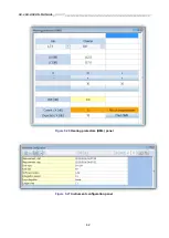
Page 62: ...SV 104 USER S MANUAL_DRAFT_______________________________________________ _ 62 Figure 5 26 Hearing protectors HML panel Figure 5 27 Instrument configuration panel ...

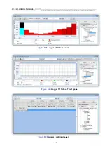
Page 63: ...SV 104 USER S MANUAL_DRAFT_______________________________________________ _ 63 Figure 5 28 Logger 1 1 Octave panel Figure 5 29 Logger 1 1 Octave TSect panel Figure 5 30 Logger combined panel ...

Page 64: ...SV 104 USER S MANUAL_DRAFT_______________________________________________ _ 64 Figure 5 31 Logger results panel Figure 5 32 Logger Statistics panel ...

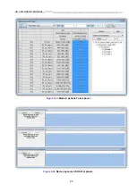
Page 65: ...SV 104 USER S MANUAL_DRAFT_______________________________________________ _ 65 Figure 5 33 Marked periods Totals panel Figure 5 34 Noise exposure ISO 9612 panels ...

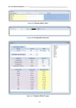
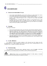
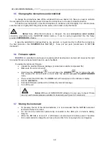
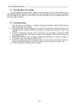
Page 66: ...SV 104 USER S MANUAL_DRAFT_______________________________________________ _ 66 Figure 5 35 Session header panel Figure 5 36 Configurable Text panel Figure 5 37 Powerfull What if panel ...

Page 67: ...can affect the measurements Take off the windshield shake off any dirt and clean it with damp cloth If necessary change the windshield to new one The foam windshield is considered a consumable item and will need replacing if it becomes lost or its condition deteriorates too much Packs of 3 replacement windshields are available under the part number SA 122_3 Pay special attention that the SV 27 mic...

Page 68: ...on path of development and as such reserves the right to provide firmware enhancements based on user s feedback To update the instrument firmware Unpack the provided firmware package provided as a suitable compressed file Make sure the unit is turned off Hold down the PROFILE key and press the ENTER key to turn on the unit This ensures the unit will switch on and enter the special reprogramming BO...

Page 69: ...rce 2 If the incorrect time or date is displayed when turning on the instrument connect the device to the computer and use Supervisor software to set the time and date see ensuring PC clock is set correctly 3 In case the instrument is not able to turn on ensure the unit is charged by connecting to USB or recommended charger This ensures the battery is not exhausted Then proceed with hardware reset...

Page 70: ...8 320 or 48 22 51 88 322 Office hours are 8 00 a m to 4 00 p m Central European Time E mail at office svantek com Internet at www svantek com Address SVANTEK Sp z o o Strzygłowska 81 04 872 Warszawa Poland Notice International customers Contact your local authorized distributor from whom the product was purchased You can obtain the name and contact information of your local authorized distributor ...

Page 71: ... P Periodic testing 67 Positioning 38 Primary parameters view mode 24 Profile 19 21 R Resetting the dosimeter 39 Results list view mode 24 Running spl view mode 23 S Scroll 19 21 49 Security lock 38 Service 70 Software options 14 Sound pressure 9 Standards 10 Starting and stopping measurement run 37 U Unit name 31 V Vibration marker 53 View mode 23 Voice comments 36 W Windshield 17 I I I In n n ns...

Reviews: