background image

FI SYSTEM DIAGNOSIS     5-49

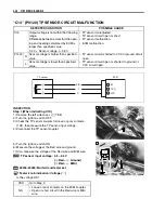
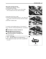
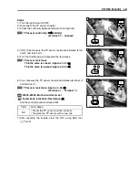
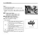
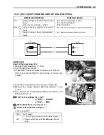
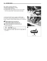
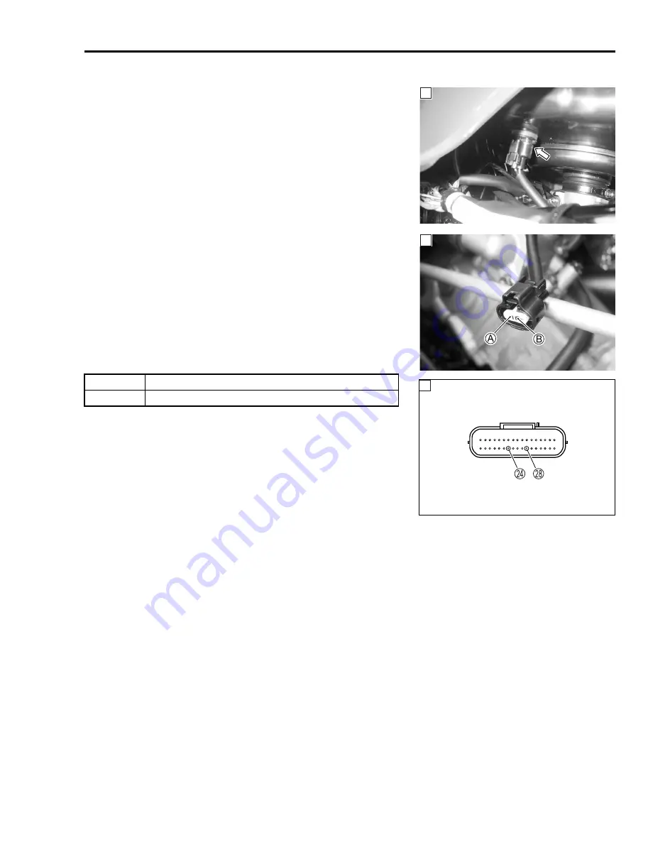
Step 1 (When indicating P0110-H:)

1) Remove the left side cover. (

$

8-8)

2) Turn the ignition switch OFF.
3) Check the IAT sensor coupler for loose or poor contacts.

If OK, then check the IAT sensor lead wire continuity.

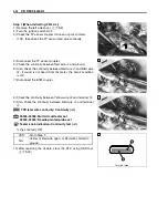
4) Disconnect the IAT sensor coupler and ECM coupler.
5) Check the continuity between Dg wire 


A

 and terminal 


R

.

6) Also, check the continuity between B/Br wire 


B

 and terminal


N

.

%

09900-25008: Multi-circuit tester set
09900-25009: Needle pointed probe set

7

Tester knob indication: Continuity test (

6

)

Is the continuity OK?

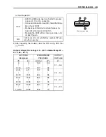
7) After repairing the trouble, clear the DTC using SDS tool.

(

$

5-23)

1

YES

Go to Step 2.

NO

Dg or B/Br wire open.

1

1

Terminal side

Summary of Contents for LT-A700X 2004

Page 1: ...Printed in U S A K5 99500 46060 01E LT A700X_01E SERVICE MANUAL 2004 9 15 for PS printing 9 9 5 0 0 4 6 0 6 0 0 1 E TOP BOTTOM ...

Page 2: ...rs of fast and reli able service COPYRIGHT SUZUKI MOTOR CORPORATION 2004 This manual has been prepared on the basis of the latest specifications at the time of publi cation If modifications have been made since then differences may exist between the con tent of this manual and the actual vehicle Illustrations in this manual are used to show the basic principles of operation and work procedures The...

Page 3: ...ge you need COMPONENT PARTS AND WORK TO BE DONE Under the name of each system or unit is its exploded view Work instructions and other service information such as the tightening torque lubricating points and locking agent points are provided Example 1 TP sensor 2 ISC valve 3 IAP sensor 4 Fuel delivery pipe 5 O ring 6 Fuel injector 7 Cushion seal 8 Vacuum hose 9 Throttle linkage cover 0 IAP sensor ...

Page 4: ... THREAD LOCK SUPER 1360 99000 32130 Apply molybdenum oil solution mixture of engine oil and SUZUKl MOLY PASTE in a ratio of 1 1 Apply or use brake fluid Apply SUZUKI SUPER GREASE A 99000 25030 USA 99000 25010 Others Measure in voltage range Apply SUZUKI SILICONE GREASE 99000 25100 Measure in resistance range Apply SUZUKI MOLY PASTE 99000 25140 Measure in current range Apply WATER RESISTANCE GREASE...

Page 5: ... Current DIFF LOCK Relay Differential Lock Relay DMC Dealer Mode Coupler DOHC Double Over Head Camshaft DRL Daytime Running Light E ECM Engine Control Module Engine Control Unit ECU FI Control Unit ECT Sensor Engine Coolant Temperature Sensor ECTS Water Temp Sensor WTS F FI Fuel Injection Fuel Injector FP Fuel Pump FPR Fuel Pressure Regulator FP Relay Fuel Pump Relay G GEN Generator GND Ground GP ...

Page 6: ...en Oxides O OHC Over Head Camshaft OPS Oil Pressure Switch P PCV Positive Crankcase Ventilation Crankcase Breather R REC Rectifier REG Regulator RH Right Hand ROM Read Only Memory S SAE Society of Automotive Engineers SDS Suzuki Diagnosis System T TO Sensor Tip Over Sensor TOS TP Sensor Throttle Position Sensor TPS ...

Page 7: ...Y Green with Yellow tracer Gr B Gray with Black tracer Gr R Gray with Red tracer Gr W Gray with White tracer Gr Y Gray with Yellow tracer O B Orange with Black tracer O Bl Orange with Blue tracer O G Orange with Green tracer O R Orange with Red tracer O W Orange with White tracer O Y Orange with Yellow tracer P B Pink with Black tracer P W Pink with White tracer R B Red with Black tracer R Bl Red ...

Page 8: ...1 4 SERIAL NUMBER LOCATION 1 4 FUEL OIL AND ENGINE COOLANT RECOMMENDATION 1 5 FUEL FOR USA AND CANADA 1 5 FUEL FOR OTHER COUNTRIES 1 5 ENGINE OIL FOR USA 1 5 ENGINE OIL FOR OTHER COUNTRIES 1 5 FRONT DIFFERENTIAL GEAR OIL 1 5 REAR DRIVE FINAL GEAR OIL 1 5 BRAKE FLUID 1 5 ENGINE COOLANT 1 6 WATER FOR MIXING 1 6 ANTI FREEZE ENGINE COOLANT 1 6 LIQUID AMOUNT OF WATER ENGINE COOLANT 1 6 BREAK IN PROCEDU...

Page 9: ... use good judgement and basic mechanical safety principles If you are unsure about how to perform a particular service operation ask a more experienced mechanic for advice GENERAL PRECAUTIONS Proper service and repair procedures are important for the safety of the service mechanic and the safety and reliability of the vehicle When 2 or more persons work together pay attention to the safety of each...

Page 10: ...d nuts tighten the larger sizes first Always tighten the bolts and nuts diagonally from the inside toward outside and to the speci fied tightening torque Whenever you remove oil seals gaskets packing O rings locking washers self locking nuts cotter pins circlips and certain other parts as specified be sure to replace them with new ones Also before installing these new parts be sure to remove any l...

Page 11: ...rkets SERIAL NUMBER LOCATION The frame serial number or V I N Vehicle Identification Number 1 is stamped on the left side of the front frame pipe The engine serial number 2 is located on the right side of the crankcase These numbers are required especially for registering the machine and ordering spare parts RIGHT SIDE LEFT SIDE ...

Page 12: ...to ensure longer ser vice life of your vehicle Use only oils which are rated SF or SG under the API service classification The recommended viscosity is SAE 10W 40 If SAE 10W 40 motor oil is not available select an alternative according to the right chart FRONT DIFFERENTIAL GEAR OIL Use hypoid gear oil that meets the API service classification GL 5 and is rated SAE 90 Use a hypoid gear oil with a r...

Page 13: ...ot go down to freezing point Suzuki recommends the use of SUZUKI COOLANT anti freeze engine coolant If this is not available use an equivalent which is compatible with an aluminum radiator LIQUID AMOUNT OF WATER ENGINE COOLANT Solution capacity total Approx 2 450 ml 2 59 2 16 US Imp qt For engine coolant mixture information refer to cooling system section in page 7 2 Mixing of anti freeze engine c...

Page 14: ...jecting the engine to maximum stresses The future performance and reliability of the engine depends on the care and restraint exercised during its early life The general rules are as follows Keep to these break in engine speed limits Brake in engine speeds Initial 500 km 300 miles Less than 1 2 throttle Upon reaching an odometer reading of 500 km 300 miles you can subject the vehicle to full throt...

Page 15: ...label A 8 General warning label A For E 28 9 Warning no passenger label A 0 AGE 16 label A For E 28 A Manual notice label A For E 33 B Max AMP caution label A Except for E 28 C Max AMP caution label A For E 28 D Fuel caution label A For E 24 E Front carrier warning label A For E 24 33 F Front carrier warning label A For E 17 28 G Rear carrier warning label A For E 24 33 H Rear carrier warning labe...

Page 16: ...16 in Stroke 85 0 mm 3 346 in Displacement 695 cm 42 4 cu in Compression ratio 10 0 1 Fuel system Fuel injection Air cleaner Nonwoven fabric element Starter system Electric and recoil starter Lubrication system Wet sump Idle speed 1 300 100 r min DRIVE TRAIN Clutch Wet shoe automatic centrifugal type Transmission Automatic variable ratio V belt Transfer 2 speed forward with reverse Gearshift patte...

Page 17: ...plug NGK CR6E or DENSO U20ESR N Battery 12 V 64 8 kC 18 Ah 10 HR Generator Three phase A C generator Main fuse 30 A Fuse 10 10 10 10 15 15 A Headlight 12 V 30 30 W 2 Auxiliary light 12 V 40 W Brake light Taillight 12 V 21 5 W Backup light 12 V 21 W E 17 Speedometer light LED Neutral indicator light LED High beam indicator light LED E 17 Coolant temperature FI warning light LED Reverse indicator li...

Page 18: ...L FILTER 2 12 DIFFERENTIAL GEAR OIL INSPECTION 2 14 DIFFERENTIAL GEAR OIL REPLACEMENT 2 14 FINAL GEAR OIL 2 15 ENGINE COOLANT 2 16 RADIATOR 2 17 RADIATOR HOSES 2 17 DRIVE BELT 2 18 BRAKES 2 22 BRAKE FLUID 2 23 BRAKE HOSES 2 25 TIRES 2 25 STEERING 2 26 SUSPENSIONS 2 27 CHASSIS NUTS AND BOLTS 2 28 GENERAL LUBRICATION 2 30 COMPRESSION PRESSURE CHECK 2 31 COMPRESSION TEST PROCEDURE 2 31 OIL PRESSURE C...

Page 19: ...al Item km Initial 200 Every 1 000 Every 2 000 miles Initial 100 Every 600 Every 1 200 months 1 3 6 Air cleaner C C Exhaust pipe nuts and muffler mounting bolts T T T Valve clearance I I Spark plug I Replace every 6 000 km 4 000 miles Spark arrester C Fuel line I I Replace every four years Throttle cable play I I I Throttle body I I Engine oil and oil filter R R Differential gear oil I Replace eve...

Page 20: ...t inner fender 8 6 Right inner fender 8 6 Left side cover 8 8 Right side cover 8 8 Left mud guard 8 8 Right mud guard 8 8 Rear carrier 8 9 Fuel tank cover 8 10 Rear fender 8 10 AIR CLEANER If the air cleaner element is clogged with dust intake resistance will be increased which results decrease in power output and increase in fuel consumption Check and clean the air cleaner element in the followin...

Page 21: ...inside of the air cleaner element If air pressure is used on the other side dirt will be forced into the pores of the air cleaner element thus restricting air flow through the air cleaner element In driving under dusty conditions clean the air cleaner element more frequently The surest way to accelerate engine wear is to operate the engine without the ele ment or to use a worn element Make sure th...

Page 22: ...N m 2 3 kgf m 16 5 lb ft VALVE CLEARANCE Excessive valve clearance results in valve noise and insufficient valve clearance results in valve damage and reduced power Check the intake and exhaust valve clearances at the interval indicated above and adjust the valve clearances to specification if necessary Remove the front fender 8 5 Remove the cylinder head cover 3 13 Remove the recoil starter 3 13 ...

Page 23: ...e TDC line A on the starter clutch to the lug mark B Read the valve clearance at all the valves with the special tool If the clearance is out of specification adjust the clearance 2 7 09900 20803 Thickness gauge Valve clearance when cold IN 0 10 0 20 mm 0 004 0 008 in EX 0 20 0 30 mm 0 008 0 012 in ...

Page 24: ...e oil to tappet shim top and bottom faces When seating the tappet shim be sure the figure printed sur face faces the tappet NOTE Reinstall the camshafts in the specified manner 3 101 After replacing the tappet shim and camshafts rotate the engine so that the tappet is depressed fully This will squeeze out oil trapped between the shim and the tappet that could cause an incorrect measurement Then ch...

Page 25: ...2 8 PERIODIC MAINTENANCE INTAKE SIDE ...

Page 26: ...PERIODIC MAINTENANCE 2 9 EXHAUST SIDE ...

Page 27: ... gap Standard Spark plug gap 0 7 0 8 mm 0 028 0 031 in 09900 20803 Thickness gauge ELECTRODE Check the condition of the electrode If the electrode is extremely worn or burnt replace the spark plug with a new one Also replace the spark plug if it has a broken insulator dam aged threads etc Inspect every 2 000 km 1 200 miles 6 months Replace every 6 000 km 4 000 miles Standard Cold type NGK CR6E CR7...

Page 28: ...y brush Reinstall the spark arrester pipe 2 FUEL LINE Inspect the fuel feed hose for damage and fuel leakage If any damages are found replace it with a new one When replacing the fuel feed hose remove the fuel tank side cover 6 2 To avoid damaging the cylinder head threads first tighten the spark plug by hand and then tighten it to the specified torque using the spark plug wrench Clean every 2 000...

Page 29: ...oil pan under the drain plug 1 and then drain out the engine oil by removing the engine oil drain plug 1 and engine oil filler cap 2 Tighten the drain plug with the new washer to the specified torque and then pour the new oil through the oil filler hole When performing an oil change without oil filter replace ment the engine will hold about 2 3 L 2 4 US qt 2 0 lmp qt of oil Use an engine oil that ...

Page 30: ...r mount ing surface Then tighten the oil filter two full turns with the special tool 09915 40610 Oil filter wrench NOTE To properly tighten the oil filter use the special tool Never tighten the oil filter by hand Pour the new engine oil through the oil filler hole When per forming the oil filter change the engine will hold about 2 5 L 2 6 US qt 2 2 Imp qt of oil Check the oil level 2 12 Add new en...

Page 31: ...en the oil drain plug 3 to the specified torque and pour fresh oil through the oil filler hole until it overflows from the oil level hole Tighten the oil level plug 1 and oil filler plug 2 to the speci fied torque Install the front under cover Differential gear oil specification Hypoid gear oil SAE 90 API grade GL 5 NOTE Use hypoid gear oil SAE 80 API grade GL 5 if the vehicle is ridden where the ...

Page 32: ...rear under cover 2 Place an oil pan below the final gear case Drain oil by removing the oil drain plug 3 and oil filler plug 1 Tighten the oil drain plug 3 to the specified torque and pour fresh oil through the oil filler hole until the oil level reaches the bottom tip of the thread Tighten the oil filler plug 1 securely Install the rear under cover 2 Final gear oil specification Mobil fluid 424 F...

Page 33: ...sary Tighten the drain plug 5 to the specified torque Engine coolant drain plug 13 N m 1 3 kgf m 9 5 lb ft Pour the specified engine coolant into the reservoir tank Engine coolant Use and antifreeze designed for aluminum radiators mixed with distilled water only Water antifreeze mixture ratio 50 50 40 60 NOTE For engine coolant information refer to page 7 2 Repalce the engine coolant every two yea...

Page 34: ... lmp qt RADIATOR Inspect the radiator for damage and engine coolant leakage If any damages are found replace it with a new one RADIATOR HOSES Inspect the radiator hoses for damage and engine coolant leak age If any damages are found replace them with new ones Repeat the above procedure several times and make sure the radiator is filled with engine coolant to the upper line of the engine coolant re...

Page 35: ...ght mud guard 8 8 Remove the right footrest bar 1 Remove the drive belt cover Remove the cap Hold the movable drive face with the special tool and loose the movable drive face bolt 1 09930 40113 Rotor holder Inspect every 1 000 km 600 miles 3 months Replace every 2 000 km 1 200 miles 6 months ...

Page 36: ...holder Remove the movable drive face bolt 1 and housing bolts Remove the dowel pins 3 Remove the movable drive face 4 Remove the movable driven face bolt 2 and movable driven face 5 with drive belt 6 Remove the drive bolt 6 INSPECTION Inspect the drive belt for wear and damage If any cracks or damages are found replace it with a new one ...

Page 37: ...shaft and temporally tighten the nut Install the movable drive face assembly NOTE Degrease the movable drive face assembly Use nonflammable cleaning solvent to wip off oily or greasy matter and make its surfaces completely dry Install the callar and movable drive face bolt NOTE Be careful direction of the collar Fit the drive belt to the movable driven face so that the arrows on the drive belt out...

Page 38: ...1 0 kgf m 79 5 lb ft Install the movable drive face cover Hold the movable driven face with the special tool and tighten the bolts to the specified torque 09930 40113 Rotor holder Movable driven face bolt 110 N m 11 0 kgf m 79 5 lb ft Turn the fixed drive face until the drive belt is properly seated and both the drive and driven face rotate together smoothly and without slipping ...

Page 39: ... is out of the limit replace the friction plate as a set 8 60 REAR BRAKE PEDAL AND LEVER The procedure for adjusting the rear brake pedal and brake lever is as follows NOTE First adjust the brake pedal and then adjust the brake lever BRAKE PEDAL Turn the adjuster 1 until the pedal height 2 comes to the specification after loosening the locknut 3 Make sure to tighten the locknut 3 securely Brake pe...

Page 40: ...E FLUID LEVEL Place the handlebar straight Check the brake fluid level by observing the lower limit line on the front brake fluid reservoir When the brake fluid level is below the lower limit line replen ish with brake fluid that meets the following specification Specification and classification DOT 4 Inspect every 1 000 km 600 miles 3 months Replace every two years The brake system of this vehicl...

Page 41: ... of the hose into a receptacle Squeeze and release the brake lever or the brake pedal sev eral times in rapid succession and squeeze the lever or the pedal fully without releasing it Loosen the air bleeder valve by turning it a quarter of a turn so that the brake fluid runs into the receptacle this will remove the tension of the brake lever causing it to touch the handlebar grip or the brake pedal...

Page 42: ...wing specification 09900 20805 Tire depth gauge Service Limit Tire tread depth Front 4 0 mm 0 16 in Rear 4 0 mm 0 16 in TIRE PRESSURE If the tire pressure is too high or too low steering will be adversely affected and tire wear will increase Therefore main tain the correct tire pressure for good roadability and a longer tire life Cold inflation tire pressure is as follows VEHICLE LOAD CAPACITY LIM...

Page 43: ...left until the toe out is within the specified range B A Toe out Toe out Standard 10 4 mm 0 39 0 16 in If the toe out is out of specification bring it into the specified range 8 52 To minimize the possiblility of tire damage from over inflation we strongly recommended that a man ual type air pump be used rather than a high pressure air compressor as found in service stations When fill ing air into...

Page 44: ...els 8 13 Inspect the wishbone arm and bushing for scratches wear or damage If any damages are found replace them with new ones 8 36 and 8 69 Inspect the front and rear shock absorbers for oil leakage or damage If any damages are found replace them with new ones 8 36 and 8 69 Inspect every 2 000 km 1 200 miles 6 months ...

Page 45: ...11 0 79 5 8 Wheel set nut front and rear 60 6 0 43 5 9 Steering knuckle end nut upper and lower 29 2 9 21 0 0 Front shock absorber mounting nut lower 60 6 0 43 5 A Front shock absorber mounting bolt upper 55 5 5 40 0 B Tie rod end nut 29 2 9 21 0 C Tie rod locknut 45 4 5 32 5 D Front brake air bleeder valve 5 5 0 55 4 0 E Front brake caliper mounting bolt 26 2 6 19 0 F Footrest bar mounting bolt M...

Page 46: ...PERIODIC MAINTENANCE 2 29 ...

Page 47: ...int spline Grease 2 Brake lever holder and throttle lever 6 Drive belt cover bearing inner race 3 Brake pedal 4 Propeller shaft joint spline NOTE Before lubricating each part remove any rust and wipe off any grease oil dirt or grime Lubricate exposed parts which are subject to rust with a rust preventative spray especially whenever the vehicle has been operated under wet or rainy conditions Lubric...

Page 48: ...fective cylinder head gasket NOTE When the compression pressure goes below specification check the engine for conditions listed above COMPRESSION TEST PROCEDURE NOTE Before testing the engine for compression pressure make sure that the cylinder head nuts are tightened to the specified torque and the valves are properly adjusted Warm up the engine before testing Make sure that the battery is fully ...

Page 49: ... Engine oil viscosity is too high Clogged oil passage Combination of the above items OIL PRESSURE TEST PROCEDURE Connect the tachometer onto the spark plug high tension cord Remove the right inner fender 8 6 Remove the cooling duct Remove the main oil gallery plug 1 Install the oil pressure gauge and adaptor into the main oil gallery Warm up the engine as follows Summer 10 minutes at 2 000 r min W...

Page 50: ...erform the following Remove the fuel tank cover Warm up the engine INITIAL ENGAGEMENT INSPECTION Connect the tachometer or the multi circuit tester onto the spark plug high tension cord Start the engine Shift the range lever to the High position Slowly open the throttle and note the engine speed r min when the vehicle begins to move forward 09900 26006 Tachometer or 09900 25008 Multi circuit teste...

Page 51: ... front and rear brakes as firmly as possible Fully open the throttle for a brief period and note the maxi mum engine speed sustained during the test cycle Lock up speed 3 500 4 100 r min If the lock up speed r min does not coincide with the standard range inspect the following items for any abnormalities Clutch shoe 3 49 Clutch wheel 3 49 Movable drive and driven face 3 51 Do not apply full power ...

Page 52: ...D SERVICING 3 28 CAMSHAFT AND CYLINDER HEAD 3 28 CAM CHAIN TENSIONER 3 43 CAM CHAIN GUIDE 3 43 CYLINDER 3 43 PISTON 3 45 CONROD CRANKSHAFT 3 47 STARTER TORQUE LIMITER 3 48 PCV HOSE 3 48 CLUTCH 3 49 MOVABLE DRIVE FACE AND DRIVEN FACE 3 51 DRIVE BELT 3 58 OIL PUMP 3 58 TRANSFER 3 59 GEARSHIFT FORK 3 62 GEARSHIFT CAM 3 63 CRANKSHAFT 3 64 DRIVE TRAIN FRONT AND REAR OUTPUT SHAFT 3 66 SHIM ADJUSTMENT 3 ...

Page 53: ...ENTER PARTS REMOVAL INSTALLATION Recoil starter 3 13 3 103 Water pump 3 16 3 96 Starter cup 3 16 3 95 Speed sensor 3 78 3 79 PARTS REMOVAL INSTALLATION Clutch cover 3 20 3 91 Movable drive driven face 3 21 3 89 Fixed drive face 3 22 3 88 Gear position switch 3 22 3 88 PARTS REMOVAL INSTALLATION Starter motor 3 12 3 103 Cam chain tensioner 3 14 3 100 Cylinder head cover 3 13 3 102 Camshaft 3 13 3 1...

Page 54: ...eps Drain engine oil 2 12 Drain engine coolant 2 16 Remove the seat 8 4 Remove the left and right inner fender 8 6 Remove the rear propeller shaft 4 35 Disconnect the battery lead wires Remove the battery stay and the battery Remove the front fender 8 5 Remove the rear fender 8 10 Disconnect the water hoses When disconnecting the battery lead wires be sure to disconnect the battery lead wire first...

Page 55: ...the air cleaner box Disconnect the injector coupler 4 and TPS coupler 5 Disconnect the ISC valve coupler 6 and fuel feed hose 7 Remove the throttle body Disconnect the ECT sensor coupler Remove the transfer shift lever assy mounting bolts Remove the transfer shift cam lever 8 Remove the shift lever assy ...

Page 56: ...he speed sensor coupler and clamp Disconnect the couplers and wiring harness clamp Remove the differential relay stay 1 Remove the regulator rectifier 2 Remove the cooling ducts Intake and outlet Disconnect the spark plug cap ...

Page 57: ...3 6 ENGINE Remove the exhaust pipe bolts Remove the muffler Remove the right footrest bar mounting bolts 1 Remove the rear brake wire clamp bolt 2 Remove the right footrest bar 3 ...

Page 58: ...INE 3 7 Remove the rear brake pedal Remove the front differential mounting bolts nuts Slide the front differential assy forward Remove the front propeller shaft spring Remove the engine mounting bolts nuts ...

Page 59: ...3 8 ENGINE Remove the engine from the right side ...

Page 60: ...ENGINE 3 9 ENGINE INSTALLATION Remount the engine in the reverse order of engine removal Pay attention to the following points ITEM N m kgf m lb ft A 60 6 0 43 5 B 60 6 0 43 5 ...

Page 61: ...d torque Engine mounting nut 60 N m 6 0 kgf m 43 5 lb ft Tighten the front differential gear mounting nuts to the speci fied torque Apply thread lock to the nuts 99000 32030 THREAD LOCK SUPER 1303 Front differential gear mounting nut 50 N m 5 0 kgf m 36 0 lb ft ...

Page 62: ...en them to the specified torque 99000 32030 THREAD LOCK SUPER 1303 Footrest bolt M8 26 N m 2 6 kgf m 19 0 lb ft M10 55 N m 5 5 kgf m 40 0 lb ft Install the new gasket and tighten the muffler mounting bolts and exhaust pipe nuts to the specified torque Muffler mounting bolt 23 N m 2 3 kgf m 16 5 lb ft Exhaust pipe nut 23 N m 2 3 kgf m 16 5 lb ft ...

Page 63: ...HAFT Remove the front propeller shaft 4 19 SPARK PLUG Remove the spark plug STARTER MOTOR AND PCV HOSE Remove the starter motor 1 Remove the PCV Positive Crankcase Ventilation hose 2 WATER HOSE AND WATER UNION Remove the water hoses 1 and 2 Remove the water union 3 ...

Page 64: ... HEAD COVER Remove the cylinder head cover 1 CAMSHAFT Turn the crankshaft to bring the TDC line A on the starter clutch to the index mark B of the crankcase NOTE At the above condition the piston is at TDC of compression stroke and also the engraved lines C on the camshafts are par allel with the mating surface of the cylinder head cover ...

Page 65: ...move the cam chain tensioner 2 with the spring and O ring CYLINDER HEAD Remove the cam drive idle gear sprocket 1 by removing its shaft 2 with the copper washer 3 and the thrust washer 4 NOTE Be careful not to drop the thrust washer 4 into the crankcase Remove the cylinder head bolts M6 5 NOTE Loosen the cylinder nuts 3 15 Be sure to loosen the camshaft journal holder bolts evenly by shifting the ...

Page 66: ...DER Remove the dowel pins 1 and gasket 2 Remove the cam chain guide 3 Remove the cylinder nuts 4 Remove the cylinder 5 Remove the dowel pins 6 and gasket 7 NOTE Be careful not to drop the dowel pins 6 into the crankcase PISTON Remove the piston by removing the piston pin circlip 1 NOTE Place a clean rag under the piston so as not to drop the piston pin circlip into the crankcase ...

Page 67: ...ilter with the special tool 09915 40610 Oil filter wrench WATER PUMP Remove the water pump 1 GENERATOR COVER Remove the starter cup nut with a suitable bar 1 Remove the starter cup 2 Remove the generator cover 3 and clamp 4 Remove the dowel pins 5 and gasket 6 ...

Page 68: ...e washer 1 and starter idle gear 2 GEARSHIFT Remove the washers 1 and gearshift shaft 2 Remove the cam driven gear 3 by removing its bolt 4 Remove the gearshift cam stopper bolt 5 gearshift cam stopper 6 washer and return spring 7 TRANSFER OUTPUT DRIVE GEAR Remove the snap ring 1 and transfer output drive gear 2 ...

Page 69: ...Remove the generator rotor bolt 1 Install the special tool to the crankshaft end 09930 31921 Rotor remover attachment Remove the generator rotor 2 with the special tool 09930 30721 Rotor remover Remove the key 3 Remove the starter driven gear 4 ...

Page 70: ...crankcase Remove the oil pump drive chain 2 and oil pump driven gear 3 Remove the pin 4 and washer 5 NOTE Be careful not to drop the pin 4 and washer 5 into the crank case Remove the oil pump 6 BALANCER SHAFT DRIVE DRIVEN GEAR Remove the balancer shaft driven gear bolts with the special tool 09924 52460 Socket wrench 52 mm Remove the water pump drive gear 1 and oil pump drive gear 2 Remove the bal...

Page 71: ...ancer drive gear nut with the special tools 09920 53740 Clutch sleeve hub holder 09924 52460 Socket wrench 52 mm Remove the washer 5 and crank balancer drive gear 6 Remove the pin 7 Remove the spacer 8 CLUTCH COVER Remove the clutch cover 1 and gasket ...

Page 72: ...ial tool 09930 40113 Rotor holder Remove the movable drive face cover 1 and collar 2 Remove the dowel pins 3 Remove the movable drive face 4 MOVABLE DRIVEN FACE Remove the movable driven face bolt with the special tool Remove the movable driven face assembly and drive belt 09930 40113 Rotor holder ...

Page 73: ...Remove the clutch inner cover 2 and gasket GEAR POSITION SWITCH Remove the gear position switch 1 Remove the pins 2 and springs 3 CLUTCH HOUSING CASE Remove the clutch housing case 1 together with the clutch housing shaft 2 Remove the dowel pins 3 and gasket 4 ...

Page 74: ... holder 09930 40131 Attachment Remove the clutch shoe with the special tool 09930 30104 Sliding shaft 09920 33540 Clutch shoe remover CRANKCASE Remove the right crankcase bolts M6 and clamp 1 Remove the right crankcase bolts M8 NOTE Loosen the crankcase bolts diagonally with the smaller sizes first The clutch shoe nut has left hand threads ...

Page 75: ...e is parallel with the end face of the crankcase The crankshaft must remain in the left crankcase half 09920 13120 Crankcase separator Remove the collar 2 Remove the dowel pins 3 OIL SUMP FILTER Remove the oil sump filter 1 REAR OUTPUT SHAFT Remove the rear output shaft 1 Remove the C ring 2 ...

Page 76: ...ve the gearshift fork shaft 1 and gearshift cam 2 Remove the gearshift forks 3 Remove the transfer output shaft assembly 4 reverse idle gear 5 with shaft and transfer input shaft 6 DRIVE BEVEL GEAR Using a chisel unlock the nut ...

Page 77: ...eeve hub holder Remove the washer 1 and drive bevel gear 2 Remove the shim 3 Remove the transfer output shaft gear with a plastic mallet CRANK BALANCER Remove the crank balancer shafts 1 Do not attempt to disassemble the transfar output driven gear shaft The transfar output driven gear shaft is available only as an assembly ...

Page 78: ...ENGINE 3 27 CRANKSHAFT Install the removed generator cover 1 and tighten the bolts Remove the crankshaft with the special tool 09920 13120 Crankcase separator Remove the generator cover ...

Page 79: ...e engraved letter 1 Intake camshaft I 2 Exhaust camshaft E Inspect the cam gear teeth for wear and damage If they are worn replace the sprocket camshaft assembly and cam chain as a set AUTOMATIC DECOMPRESSION Move the automatic decompression weight by hand to inspect if it is operating smoothly If it does not operate smoothly replace the camshaft automatic decompression assembly with a new one Be ...

Page 80: ...ether or not each journal is worn down to the limit by measuring the oil clearance with the camshaft installed in place Use the plastigauge A to read the clearance at the widest por tion which is specified as follows Camshaft journal oil clearance Service Limit IN EX 0 150 mm 0 0059 in 09900 22301 Plastigauge 09900 22302 Plastigauge NOTE Install camshaft journal holders to their original positions...

Page 81: ...lace the camshaft or the cylinder head depending upon which one exceeds the specification Camshaft journal holder I D Standard IN EX 22 012 22 025 mm 0 8666 0 8671 in 09900 20602 Dial gauge 1 1000 1 mm 09900 22403 Small bore gauge 18 35 mm Camshaft journal O D Standard IN EX 21 972 21 993 mm 0 8650 0 8659 in 09900 20205 Micrometer 0 25 mm CAMSHAFT RUNOUT Measure the runout using the dial gauge Rep...

Page 82: ...sing special tools compress the valve spring and remove the two cotter halves 3 from the valve stem 09916 14510 Valve lifter 09916 14910 Valve lifter attachment 09916 84511 Tweezers Remove the valve spring retainer 4 and valve spring 5 Pull out the valve 6 from the combustion chamber side ...

Page 83: ...uge VALVE STEM RUNOUT Support the valve with V blocks and check its runout using the dial gauge as shown If the runout exceeds the service limit replace the valve Valve stem runout Service Limit 0 05 mm 0 002 in 09900 20607 Dial gauge 1 100 mm 09900 20701 Magnetic stand 09900 21304 V block set 100 mm VALVE HEAD RADIAL RUNOUT Place the dial gauge at right angles to the valve head face and measure t...

Page 84: ...vice Limit 0 35 mm 0 014 in 09900 20607 Dial gauge 1 100 mm 09900 20701 Magnetic stand VALVE STEM WEAR If the valve stem is worn down to the limit as measured with a micrometer where the clearance is found to be in excess of the limit indicated replace the valve if the stem is within the limit then replace the guide After replacing valve or guide be sure to recheck the deflection Valve stem O D St...

Page 85: ...e guide until the attachment contacts with the cyl inder head 1 After installing the valve guides re finish their guiding bores using the reamer Clean and oil the guides after reaming 09916 34550 Valve guide reamer 09916 34542 Reamer handle NOTE Be sure to cool down the cylinder head to ambient air tempera ture Insert the reamer from the combustion chamber and always turn the reamer handle clockwi...

Page 86: ...g specification Valve seat width W Standard 0 9 1 1 mm 0 035 0 043 in 09916 10911 Valve lapper set If either requirement is not met correct the seat by servicing is as follows VALVE SEAT SERVICING The valve seats 1 for both intake valve 2 and exhaust valve 3 are machined to four different angles The seat contact surface is cut 45 NOTE The valve seat contact area must be inspected after each cut 09...

Page 87: ...f the seat is pitted or burned addi tional seat conditioning with the 45 cutter is required NOTE Cut only the minimum amount necessary from the seat to pre vent the possibility of the tappet shim replacement If the contact area W is too high on the valve or if it is too wide use the 15 60 cutters for exhaust side and 30 60 cutters for intake side to lower and narrow the contact area If the contact...

Page 88: ...ake and exhaust ports with gasoline to check for leaks If any leaks occur inspect the valve seat and face for burrs or other things that could prevent the valve from sealing NOTE After servicing the valve seats be sure to check the valve clear ance after the cylinder head has been reinstalled 2 7 45 Do not use lapping compound after the final cut is made The finished valve seat should have a velve...

Page 89: ... within the range specified replace it 09900 20102 Vernier calipers Valve spring free length IN EX Service Limit 46 1 mm 1 81 in Valve spring tension IN EX Standard 182 210 N 36 35 mm 18 6 21 4 kgf 36 35 mm 41 0 47 2 lbs 1 43 in VALVE REASSEMBLY Install the valve spring seats 1 Apply MOLYBDENUM OIL SOLUTION to each oil seals 2 and press fit them into position MOLYBDENUM OIL SOLUTION Insert the val...

Page 90: ...ment 09916 84511 Tweezers Install the tappet shims 4 and tappets 5 to their original position NOTE Apply engine oil to the shim and tappet before fitting them When seating the tappet shim be sure the figure printed sur face faces the tappet CAM DRIVE IDLE GEAR SPROCKET THRUST CLEARANCE Install the cam drive idle gear sprocket 1 shaft 2 copper gas ket 3 and shim 4 to cylinder head Tighten the shaft...

Page 91: ...a microme ter Change the shim and thrust clearance should be re checked unit correct 09900 20205 Micrometer 0 25 mm Unit mm in INTAKE PIPE Remove the intake pipe 1 Color A Mark B Part No Shim thickness C Dark blue 09181 15182 1 38 1 42 0 054 0 056 Yellow 09181 15181 1 28 1 32 0 050 0 052 Light blue 09181 15176 1 18 1 22 0 046 0 048 Light green 09181 15172 1 08 1 12 0 043 0 044 Brown 09181 15166 0 ...

Page 92: ...D OIL GALLERY PLUG Remove the oil gallery plug 1 and water bypass union 2 Install the new gasket 3 and apply THREAD LOCK to the oil gallery plug 99000 3205 THREAD LOCK 1342 Apply THREAD LOCK to the thread part of water bypass union and tighten it to the specified torque 99000 32050 THREAD LOCK 1342 Water bypass union 14 N m 1 4 kgf m 10 0 lb ft Use the new O ring to prevent air from sucking throug...

Page 93: ...T Remove the thermostat bracket 1 and thermostat cover 2 Remove the thermostat THERMOSTAT INSPECTION 7 10 THERMOSTAT INSTALLATION 7 10 ECT SENSOR Remove the ECT sensor 1 ECT SENSOR INSPECTION 7 9 ECT SENSOR INSTALLATION 7 9 ...

Page 94: ...am chain guide for wear and damage If it is found to be damaged replace it with a new one CYLINDER CYLINDER DISTORTION Check the gasketed surface of the cylinder for distortion with a straightedge and thickness gauge taking a clearance reading at several places as indicated If the largest reading at any position of the straightedge exceeds the limit replace the cylinder Cylinder distortion Service...

Page 95: ...the cylinder wall for any scratches nicks or other dam age Measure the cylinder bore diameter at six places Cylinder bore Standard 102 000 102 015 mm 4 0157 4 0163 in 09900 20508 Cylinder gauge set 09900 20520 Red cylinder gauge 100 mm ...

Page 96: ...the 1st and 2nd rings using the thickness gauge If any of the clearances exceeds the limit replace both piston and piston rings Piston ring to groove clearance Service Limit 1st 0 180 mm 0 0071 in 2nd 0 150 mm 0 0059 in Piston ring groove width Standard 1st 0 83 0 85 mm 0 0327 0 0335 in 2nd 1 01 1 03 mm 0 0398 0 0406 in Oil 2 01 2 03 mm 0 0791 0 0799 in Piston ring thickness Standard 1st 1 08 1 10...

Page 97: ... end gap Service Limit 1st 0 50 mm 0 020 in 2nd 0 50 mm 0 020 in 09900 20803 Thickness gauge PISTON PIN AND PIN BORE Measure the piston pin bore inside diameter using the small bore gauge If the measurement is out of specification replace the piston Piston pin bore I D Service Limit 23 030 mm 0 9067 in 09900 20602 Dial gauge 1 1000 mm 1 mm 09900 22403 Small bore gauge 18 35 mm Measure the piston p...

Page 98: ...EARANCE Push the big end of the conrod to one side and measure the side clearance with a thickness gauge Conrod big end side clearance Service Limit 1 0 mm 0 04 in 09900 20803 Thickness gauge If the clearance exceeds the limit replace the crankshaft assem bly with a new one or bring the deflection and the side clearance within the service limit by replacing the worn parts conrod big end bearing cr...

Page 99: ...que limiter to the special tool 1 Set the 1 with the starter torque limiter to the vise Set the special tool 2 to the starter torque limiter If the slip torque is not within specification replace the starter torque limiter with a new one PCV HOSE Inspect the PCV hose for wear or damage If it is worn or damaged replace the PCV hose with a new one Do not attempt to disassemble the starter torque lim...

Page 100: ...ches cracks or uneven wear If any damages are found replace the clutch wheel with a new one STARTER CLUTCH Remove the starter clutch securing bolts Install the starter clutch in the proper direction NOTE When installing the starter clutch onto the rotor make sure the flange side A of the one way clutch faces to the rotor Face the arrow mark B to the engine side Apply engine oil to the starter clut...

Page 101: ... gener ator rotor The gear never turns in the direction of the arrow If there is anything unusual replace the one way clutch Check the starter driven gear bearing If there is anything unusual replace the bearing Remove the bearing with the special tool 09913 70210 Bearing installer remover set 040 Install the bearing with the special tool 09913 70210 Bearing installer remover set 042 ...

Page 102: ...r 4 pcs 4 Roller 8 pcs D O ring 2 pcs 5 Oil seal 2 pcs E Spring seat 6 Movable drive face F Spring 7 Drive belt G Spring plate ITEM N m kgf m lb ft 8 Fixed drive face A Movable drive face bolt A 110 11 0 79 5 9 Fixed driven face B Movable driven face bolt B 110 11 0 79 5 0 Oil seal 2 pcs C Movable driven face ring nut C 100 10 0 72 5 ...

Page 103: ...D SLIDING SURFACE Inspect each roller and their sliding surface for wear or damage If any damages are found replace the rollers as a set NOTE The rollers must always be changed as a set OIL SEAL Inspect the lip of the oil seal for wear or damage If any damage is found replace the oil seal with a new one Remove the oil seals ...

Page 104: ...d fixed drive face in the reverse order of disassembly Pay attention to the following points Apply a small amount of SUZUKI SUPER GREASE A to the bore and oil seal lip 99000 25030 SUZUKI SUPER GREASE A USA 99000 25010 SUZUKI SUPER GREASE A Others Position the eight rollers 1 on the movable drive face Mount the dampers 2 on the movable drive face plate 3 Position the movable drive face plate on the...

Page 105: ...cial tool to the movable driven face assembly and compress the movable driven face assembly by turning in the special tool handle NOTE Make sure to insert the spring end A into the slot B of the spe cial tool as shown 09922 31430 Movable driven face spring compressor Remove the movable driven face ring nut 1 Loosen the special tool handle slowly and remove the special tool Do not remove the movabl...

Page 106: ...Remove the spring seat 4 Remove the pins and rollers Remove the movable driven face 5 O RING AND OIL SEAL Inspect the O rings and oil seals for wear or damage If any damages are found replace the O rings and oil seals with new ones Remove the oil seals ...

Page 107: ...ND FIXED DRIVEN FACE Inspect the driven face for any abnormal condition such as stepped wear or discoloration caused by burning If any damages are found replace the movable driven face with a new one REASSEMBLY Install the new O rings 1 Apply SUZUKI SUPER GREASE A to the oil seal lips and movable driven face inside grease groove 99000 25030 SUZUKI SUPER GREASE A USA 99000 25010 SUZUKI SUPER GREASE...

Page 108: ...the spring ends with the holes Compress the spring with the special tool 09922 31430 Movable driven face spring compressor Tighten the movable driven face ring nut 1 temporarily Remove the special tool from the movable driven face assem bly To prevent damaging the oil seal lip from during installation slide the lip using a 0 1 mm steel sheet as a guide ...

Page 109: ...m age and measure the width of the drive belt using the vernier calipers If any damages are found or the measurement exceeds the ser vice limit replace the drive belt with a new one Drive belt width Service Limit 35 6 mm 1 40 in 09900 20101 Vernier calipers OIL PUMP Rotate the oil pump by hand and check that it moves smoothly If it does not move smoothly replace the oil pump assembly If grease or ...

Page 110: ...e following points NOTE Always use new snap rings NOTE Before installing the gears coat lightly engine oil to the transfer input output shaft 1 Washer 8 Low driven gear 2 Reverse idle gear 9 Dog 3 Reverse idle gear shaft 0 Reverse driven gear 4 Spacer A High driven gear 5 Bearing B Counter shaft 6 Oil seal C Snap ring 7 Transfer input shaft D Speed sensor ...

Page 111: ...roove A NOTE Make sure that the waved washer 3 position properly Fit the lock washer 2 into the washer 1 Never reuse a snap ring After a snap ring has been removed from a shaft it should be discarded and a new snap ring must be installed When installing a new snap ring do not expand the end gap larger than required to slip the snap ring over the shaft After installing a snap ring make sure that it...

Page 112: ...ENGINE 3 61 Install the reverse drive gear bushing 3 and low driven gear bushing 4 When installing the bushing onto the transfer output shaft aline the shaft oil hole B with the bushing oil hole C ...

Page 113: ...o groove clearance Standard 0 10 0 30 mm 0 004 0 012 in Service Limit 0 50 mm 0 020 in 09900 20803 Thickness gauge SEARSHIFT FORK GROOVE WIDTH Measure the gearshift fork groove width using the vernier cali pers Shift fork groove width Standard Reverse 5 50 5 60 mm 0 217 0 220 in High 5 50 5 60 mm 0 217 0 220 in 09900 20101 Vernier calipers GEARSHIFT FORK THICKNESS Measure the gearshift fork thickn...

Page 114: ...ed marks A of the dog with the punched mark B on the shaft 1 Gear position switch 7 Washer C Gearshift fork for Reverse 2 O ring 8 Spring D Gearshift fork for High Low 3 Gearshift shaft 9 Dog for High Low E Gearshift fork shaft 4 Snap ring 0 Snap ring F Gearshift shaft 5 Dog for Reverse A Bearing G Gearshift lever 6 Snap ring B Gearshift cam ...

Page 115: ...3 64 ENGINE CRANKSHAFT DISASSEMBLY 1 Crankshaft R 5 Washer 2 Washer 6 Crank pin 3 Conrod 7 Crankshaft L 4 Bearing ...

Page 116: ...ENGINE 3 65 REASSEMBLY Determine the width between the webs referring to the figure when rebuilding the crankshaft Crank web to web width Standard 72 9 73 1 mm 2 87 2 88 in ...

Page 117: ...3 66 ENGINE DRIVE TRAIN FRONT AND REAR OUTPUT SHAFT CONSTRUCTION 1 Shim s 4 Shim s 2 Front output shaft 5 Driven bevel gear 3 Drive bevel gear 6 Rear output shaft ...

Page 118: ... damage are found replace the front output shaft with a new one FRONT OUTPUT SHAFT INSTALLATION Install the front output shaft in the reverse order of removal REAR OUTPUT SHAFT DISASSEMBLY Unlock the nut with a chisel With the rear output shaft held immovable with a vise remove the nut Remove the washer 1 gear 2 bearing 3 and driven bevel gear 4 Replace the removed nut with a new one ...

Page 119: ...d driven bevel gears as a set REAR OUTPUT SHAFT REASSEMBLY Reassemble the rear output shaft in the reverse order of disas sembly Pay attention to the following points NOTE Before reassembly thoroughly clean all parts in cleaning sol vent Install the driven bevel gear 1 and bearing 2 NOTE The wider side A of the bearing should be positionde bevel gear side Install the shim s 3 and bearing 4 NOTE Th...

Page 120: ... NOTE Do not stake a lock portion on the nut at this stage After the backlash and tooth contact have been checked or adjusted stake the nut with a center punch With the rear output shaft held immovable with a vise tighten the new nut to the specified torque Rear output shaft nut D 100 N m 10 0 kgf m 72 5 lb ft Lock the rear output shaft nut D with a center punch ...

Page 121: ... Part No Shim thickness For driven bevel gear 3 68 24945 03G50 055 24945 03G50 058 24945 03G50 060 24945 03G50 063 24945 03G50 065 24945 03G50 068 24945 03G50 070 24945 03G50 073 24945 03G50 075 24945 03G50 078 24945 03G50 080 24945 03G50 083 24945 03G50 085 0 550 mm 0 022 in 0 575 mm 0 023 in 0 600 mm 0 024 in 0 625 mm 0 025 in 0 650 mm 0 026 in 0 675 mm 0 027 in 0 700 mm 0 028 in 0 725 mm 0 029 ...

Page 122: ...t is found to be incorrect examples 1 and 3 the shim thickness between the drive bevel gear and bearing must be changed and the tooth contact re checked until cor rect Make sure to check the backlash after the tooth con tact has been adjusted since it may have changed Adjust the tooth contact and backlash until they are both within specification If the correct tooth contact cannot be maintained wh...

Page 123: ...G50 060 24935 03G50 058 24935 03G50 055 24935 03G50 083 0 700 mm 0 0276 in 0 725 mm 0 0285 in 0 750 mm 0 0295 in 0 775 mm 0 0305 in 0 800 mm 0 0315 in 0 825 mm 0 0325 in 24935 03G50 080 24935 03G50 078 24935 03G50 075 24935 03G50 073 24935 03G50 070 24935 03G50 098 0 850 mm 0 0335 in 0 875 mm 0 0344 in 0 900 mm 0 0354 in 0 925 mm 0 0364 in 0 950 mm 0 0374 in 0 975 mm 0 0384 in 24935 03G50 095 2493...

Page 124: ...transfer output driven gear with the special tool and remove the drive bevel gear nut 09920 53740 Clutch sleeve hub holder Remove the washer 1 and drive bevel gear 2 Remove the shim 3 Remove the output shaft with a plastic mallet Do not remove the output driven gear from the output shaft ...

Page 125: ... a plastic mallet Install the shim 1 Install the drive bevel gear 2 and washer 3 Tighten the drive bevel gear nut to the specified torque with the special tool Drive bevel gear nut 100 N m 10 0 kgf m 72 5 lb ft 09920 53740 Clutch sleeve hub holder Stake the nut with a center punch ...

Page 126: ...TE If there is no abnormal noise the bearing removal is not neces sary Remove the bearing retainers Remove the bearing 1 with the special tool 09921 20240 Bearing remover set 25 mm Remove the bearings with the special tool 09913 70210 Bearing installer set 2 4 5 030 3 7 055 6 040 LEFT CRANKCASE BEARING INSTALLATION Install the bearings with the special tool 09913 70210 Bearing installer set 1 052 ...

Page 127: ...EMOVAL NOTE If there is no abnormal noise the bearing removal is not neces sary Remove the bearing retainers Remove the bearings with the special tool 09921 20240 Bearing remover set 1 2 3 20 mm 4 30 mm Remove the bearing 5 with the special tools 09923 74511 Bearing remover 09930 30104 Sliding shaft Remove the oil seal 6 and bearing 7 with the special tool 09913 70210 Bearing installer set ...

Page 128: ...he bearing face outside Install the bearing retainers NOTE When installing the bearing retainers apply THREAD LOCK to the screws 09900 32050 THREAD LOCK 1342 OIL SEAL Remove the oil seal with the special tool 09913 50121 Oil seal remover Install the oil seal with the special tool 09913 70210 Bearing installer set Use the new oil seal to prevent oil leakage ...

Page 129: ... rings 1 and 2 Remove the bearings with the special tool 09921 20240 Bearing remover set 3 4 25 mm 5 12 mm NOTE If there is no abnormal noise the bearing removal is not neces sary Remove the oil seals 09913 50121 Oil seal remover Remove the speed sensor 6 Inspect the speed sensor 9 30 ...

Page 130: ...0 SUZUKI SUPER GREASE A USA 99000 25030 SUZUKI SUPER GREASE A Others Install the speed sensor Install the oil seals with the special tool 09913 70210 Bearing installer set Install the bearings with the special tool 09913 70210 Bearing installer set Install the generator stator ...

Page 131: ...m the housing 1 Nut 6 Spring 2 Friction plate 7 Spacer 3 Ratchet guide 8 Pin 4 Ratchet 9 Reel 5 Spring cover 1 O ring 5 Reel 2 Starter cup 6 Spiral spring 3 Starter cup nut 7 Rope assembly 4 Ratchet set Wear hand and eye protection when removing the reel since the spring may quickly unwind and cause an injury ...

Page 132: ...n the starter rope on the reel properly After installing the spiral spring engage the part A of the reel with the spiral spring end 2 Hook the rope onto the hook part B of the reel turn the reel clockwise four of five times with the rope Install the pin spacer spring cover ratchet and ratchet guide NOTE Apply SUZUKI SUPER GREASE A to the shaft and ratchet guide 99000 25030 SUZUKI SUPER GREASE A US...

Page 133: ...3 82 ENGINE Pull the rope and check that the ratchet is pushed out ...

Page 134: ...cial tool NOTE Use the front fork oil seal installer and suitable bars A as an attachment 09910 32812 Crankshaft installer 09940 52861 Front fork oil seal installer CRANK BALANCER Install the crank balancershafts 1 DRIVE BEVEL GEAR Install the transtar output driven gear shaft with a plastic mal let Always keep the drive belt drive face and driven face away from any greasy matter Never fit the cra...

Page 135: ...l Tighten the drive bevel gear nut to the specified torque Drive bevel gear nut 100 N m 10 0 kgf m 72 5 lb ft 09920 53740 Clutch sleeve hub holder Bend the collar of nut to the notch at the shaft with a center punch Install the transfer input shaft 1 reverse idle gear 2 and transfer output shaft assembly 3 Install the washer 4 ...

Page 136: ...ng 1 Install the rear output shaft NOTE Be sure to fit the pin A on the bearing into the groove of the crankcase OIL SUMP FILTER Install the oil sump filter 1 NOTE Fit the projection A of the oil sump filter in the concave portion of the crankcase ...

Page 137: ...the pressure Tighten the crankcase bolts to the specified torque Crankcase bolt M6 10 N m 1 0 kgf m 7 0 lb ft M8 26 N m 2 6 kgf m 19 0 lb ft NOTE Tighten the crankcase bolts diagonally with the bigger sizes first Fit the clamp to the bolt A After the crankcase bolts have been tightened check if the each shaft rotates smoothly If a large resistance is felt to rotation try to free the shafts by tapp...

Page 138: ... ft 99000 32030 THREAD LOCK SUPER 1303 09930 40113 Rotor holder 09930 40131 Attachment Apply MOLYBDENUM OIL SOLUTION to the inside of the one way clutch MOLYBDENUM OIL SOLUTION Install the one way clutch with facing the OUTSIDE mark A outside CLUTCH HOUSING CASE Apply SUZUKI SUPER GREASE A to the O ring Install the oil jet as shown in photograph 99000 25030 SUZUKI SUPER GREASE A USA 99000 25010 SU...

Page 139: ...itch contacts 2 Install the gear position switch 3 CLUTCH INNER COVER Install the clutch inner cover and gasket FIXED DRIVE FACE Install the fixed drive face 1 NOTE Degrease the fixed drive face Use nonflammable cleaning sol vent to wipe off oily or greasy matter and make its surfases com pletely dry ...

Page 140: ...kgf m 79 5 lb ft 09930 40113 Rotor holder Install the movable drive face assembly 2 NOTE Degrease the movable drive face assembly Use nonflammable cleaning solvent to wip off oily or greasy matter and make its surfaces completely dry The drive belt should be installed so that the arrows on the drive belt periphery point in the normal turn ing direction The drive belt contact surface of the driven ...

Page 141: ...ace bolt to the specified torque with the special tool Movable drive face bolt 110 N m 11 0 kgf m 79 5 lb ft 09930 40113 Rotor holder NOTE Turn the fixed drive face until the belt is seated in and both the drive and driven faces will move together smoothly without slip Install the dowel pins 5 Install the movable drive face cover 6 ...

Page 142: ...nstall the pin 1 Install the balancer shaft drive gear and washer Hold the crank balancer shaft drive gear with the special tool 09920 53740 Clutch sleeve hub holder 09924 52460 Socket wrench 52 mm Tighten the crank balancer drive gear nut to the specified torque Crank balancer drive gear nut 150 N m 15 0 kgf m 108 5 lb ft Lock the balancer shaft drive gear nut with a center punch Use the new nut ...

Page 143: ...mp drive gear 4 and oil pump drive gear 5 NOTE Align the punched marks A as shown NOTE Pay attention to the direction of the water pump drive gear and oil pump drive gear Apply THREAD LOCK SUPER 1303 to the balancer driven gear bolts 99000 32030 THREAD LOCK SUPER 1303 OUTSIDE INSIDE ...

Page 144: ... 2 into the crank case Install the oil pump drive gear 3 with chain 4 Install the snap ring 5 NOTE Be careful not to drop the snap ring into the crankcase CAM CHAIN TENSIONER Install the cam chain tensioner 1 along with the washer 2 Tighten the cam chain tensioner bolt 3 to the specified torque Cam chain tensioner bolt 23 N m 2 3 kgf m 16 5 lb ft GENERETOR Install the starter driven gear 1 Install...

Page 145: ...ring 4 GEARSHIFT Install the gearshift cam stopper 1 NOTE Hook the return spring end A to the stopper Check the gearshift cam stopper moves smoothly Locate the gearshift cam in the neutral position Install the cam driven gear 2 NOTE Align the gearshift cam pin B with the cam driven gear hole C Reassemble the gearshift shaft Make sure that the one way clutch on the crankshaft rotor is fitted into t...

Page 146: ...r 1 starter torque limiter 2 and washers 3 GENERATOR COVER Install the dowel pins 1 and new gasket 2 Install the generator cover 3 NOTE Fit the clamp to the bolt A STARTER CUP Apply SUZUKI SUPER GREASE A to the O ring and lip of the oil seal Install the starter cup 1 99000 25030 SUZUKI SUPER GREASE A USA 99000 25010 SUZUKI SUPER GREASE A Others ...

Page 147: ...ool 2 13 09915 40610 Oil filter wrench ENGINE TOP SIDE PISTON Install the piston rings in the order of oil ring 2nd ring and 1st ring The first member to go into the oil ring groove is a spacer 1 After placing the spacer fit the two side rails 2 NOTE Side designations top and bottom are not applied to the spacer and side rails Those can be positioned each either way Use the new O ring to prevent o...

Page 148: ...ated Apply a light coat of MOLYBDENUM OIL SOLUTION to the piston pin MOLYBDENUM OIL Install the piston and piston pin NOTE When installing the piston the punched mark A on the piston head is located to the exhaust side Place a clean rag over the crankcase Install the circlip 1 1st ring 2nd ring EX IN 2nd ring Lower side rail Upper side rail 1st ring Spacer When turning the crankshaft pull the cam ...

Page 149: ...gasket 4 CYLINDER HEAD Install the cylinder head Tighten the cylinder head bolts M10 in ascending order of numbers to the specified torque Cylinder head bolt M10 Initial 25 N m 2 5 kgf m 18 0 lb ft Final 37 N m 3 7 kgf m 27 0 lb ft Tighten the cylinder base nuts 1 Tighten the cylinder head bolts M6 to the specified torque Cylinder head bolt M6 10 N m 1 0 kgf m 7 0 lb ft Use a new gasket to prevent...

Page 150: ...case Install the cam drive idle gear sprocket 1 with cam drive chain onto the cylinder head and engine the cam chain on it Aline the punched mark C on the cam drive idle gear sprocket with the embossed line D on the cylinder head Install the cam drive idle gear sprocket shaft 2 copper washer 3 and shim 4 When checking the positions remove the cam chain slack at the cam chain guide side by holding ...

Page 151: ...ft 41 N m 4 1 kgf m 29 5 lb ft CAM CHAIN TENSIONER Install the cam chain tensioner 1 and tighten the its mounting bolts to the specified torque Cam chain tensioner bolt 10 N m 1 0 kgf m 7 0 lb ft If the punched mark C does not align the embossed line D turn the crankshaft 360 1 turn to bring the line on the generator rotor to the index mark on the crankcase again and reinstall the cam drive idle g...

Page 152: ...ex mark B on the crankcase Install the dowel pins 1 The camshafts are identified by the engraved letters Before replacing the camshafts on cylinder head apply MOLYBDENUM OIL SOLUTION to their journals and cam faces Apply MOLYBDENUM OIL SOLUTION to the camshaft jour nal holders MOLYBDENUM OIL SOLUTION NOTE Before installing the camshaft check that the tappets are installed correctly Use the new O r...

Page 153: ...over Apply SUZUKI BOND to the cam end caps of the gasket as shown 99104 31140 SUZUKI BOND 1207B USA 99000 31110 SUZUKI BOND 1215 Others Tighten the head cover bolts to the specified two step torque sequentially and diagonally Head cover bolt Initial 10 N m 1 0 kgf m 7 0 lb ft Final 14 N m 1 4 kgf m 10 0 lb ft NOTE Apply engine oil to the both side of head cover washer before installing the head co...

Page 154: ...to the water union Apply engine coolant to the O ring 99000 99032 11X ENGINE COOLANT STARTER MOTOR Install the new O ring to the starter motor Apply SUZUKI SUPER GREASE A to the O ring 99000 25030 SUZUKI SUPER GREASE A USA 99000 25010 SUZUKI SUPER GREASE A Others Use a new O ring to prevent engine coolant leakage Use the new O ring to prevent oil leakage ...

Page 155: ......

Page 156: ...4 14 SHIM ADJUSTMENT 4 15 REASSEMBLY INFORMATION 4 18 FRONT PROPELLER SHAFT 4 19 REMOVAL 4 19 INSPECTION 4 19 REASSEMBLY 4 20 REAR DRIVE TRAIN 4 22 CONSTRUCTION 4 22 DISASSEMBLY 4 23 INSPECTION 4 27 REASSEMBLY 4 28 SHIM ADJUSTMENT 4 31 REASSEMBLY INFORMATION 4 34 REAR PROPELLER SHAFT 4 35 REMOVAL AND DISASSEMBLY 4 35 INSPECTION 4 37 REASSEMBLY AND REMOUNTING 4 38 ...

Page 157: ...ring L Oil seal 7 Shim left side M Boot 8 2WD 4WD shifting cam N Front propeller shaft spring 9 2WD 4WD shifting fork O Front propeller shaft 0 2WD 4WD shifting fork shaft P Circlip A Oil seal Q Univrsal joint B O ring R Boot C Actuator S Breather rubber case D Bearing A Front drive train differential gear case mounting nut ITEM N m kgf m lb ft E Drive bevel gear B Front drive train differential g...

Page 158: ... inboard joint 1 of the front drive shaft and tug the drive shaft horizontally NOTE If it is difficult to remove the front drive shaft from the front differ ential gear case use the suitable tool Remove the brake sensor lead wire clamp Remove the actuator lead wire and brake sensor lead wire band Disconnect the actuator lead wire coupler ...

Page 159: ...bly out of the frame DISASSEMBLY ACTUATOR Remove the actuator assembly MOTOR INSPECTION 9 22 FRONT DRIVE TRAIN DIFFERENTIAL GEAR Remove the front drive train differential gear case cover bolts Remove the case cover with the plastic mallet Remove the 2WD 4WD shifting cam bearing snap ring Remove the 2WD 4WD shifting cam 1 from the gear case cover ...

Page 160: ...ly 2 Remove the shims from the case and case cover 2WD 4WD SHIFTING DEVICE Remove the gear shifting fork shaft 1 Remove the gear shifting fork 2 Remove the snap ring Remove the oil seal cap 3 oil seal 4 and snap ring 5 The removed oil seal must be replaced with a new one ...

Page 161: ...4 6 DRIVE TRAIN Remove the input shaft 6 Remove the gear shifting sleeve 7 Remove the snap ring 8 DRIVE BEVEL GEAR Remove the snap ring 1 Remove the drive bevel gear 2 together with the bearing ...

Page 162: ...3 70210 Bearing installer set 2WD 4WD SHIFTING CAM BEARING Inspect the 2WD 4WD shifting cam bearing for abnormal noise or smooth rotation If any wear or damage is found replace the bearing with a new one Remove the bearing with the special tool 09913 70210 Bearing installer set DRIVE BEVEL GEAR PILOT BEARING Inspect the drive bevel gear pilot bearing for wear or damage If any wear or damage is fou...

Page 163: ...ew one Remove the bearing with the special tool 09913 60910 Bearing gear puller 09913 70210 Bearing installer BREATHER RUBBER CASE Inspect the breather rubber case for wear or damage If any wear or damage is found replace it with a new one Make sure the joint of the rubber case fits tightly Do not attempt to disassemble the front differential gear assembly This part is available only as an assembl...

Page 164: ...ll the parts with cleaning solvent Install the new bearings to the front differential gear assembly with the special tool 09913 70210 Bearing installer set Install the new oil seals into the front differential gear case and case cover with the special tool Apply grease to the oil seal lips 09913 70210 Bearing installer set 99000 25030 SUZUKI SUPER GREASE A USA 99000 25010 SUZUKI SUPER GREASE A Oth...

Page 165: ...t drive train differential gear case with the special tool 09913 70210 Bearing installer set Install the new bearing onto the input shaft with the special tool 09913 70210 Bearing installer set Install the snap ring Install the drive bevel gear with bearing to the front drive train differential gear case and fix the new snap ring 1 09913 70210 Bearing installer set ...

Page 166: ...nstall the input shaft into the gear case with the special tool 09913 70210 Bearing installer set 09924 74550 Final gear case oil seal installer 09922 21410 Long socket 46 mm Install the 2WD 4WD shifting fork 1 as shown in the photo graph Apply front differential gear oil to the 2WD 4WD sifting fork shaft 2 Install the shaft as shown in the photograph ...

Page 167: ... of the shifting cam 5 After the backlash and tooth contact have been checked or adjusted apply bond to the mating surface of the case 99104 31140 SUZUKI BOND 1207B USA 1 99000 31110 SUZUKI BOND 1215 Others Turn the shifting cam 5 clockwise and install the shifting fork pin to the bottom Align the 2WD 4WD shifting fork pin 6 with the groove of the shifting cam 7 when remounting ...

Page 168: ... 0 lb ft NOTE After the backlash and tooth contact have been checked or adjusted apply thread lock to the case cover bolts Apply grease to the new O ring 99000 25030 SUZUKI SUPER GREASE A USA 99000 25010 SUZUKI SUPER GREASE A Others Apply thread lock to the M8 bolt Install the actuator assembly and tighten its mounting bolts to the specified torque 99000 32030 THREAD LOCK SUPER 1303 Actuator mount...

Page 169: ...ar case mounting nut 50 N m 5 0 kgf m 36 0 lb ft Install a new stopper ring into the groove of front differential gear spline Apply grease to the spline of the front drive shafts and install the front drive shafts to the front differential gear case 99000 25030 SUZUKI SUPER GREASE A USA 99000 25010 SUZUKI SUPER GREASE A Others NOTE After installing both drive shafts make sure the stopper rings are...

Page 170: ...e back lash is within specification Refer to the chart at the right for the appropriate shim thickness Backlash Standard 0 05 0 10 mm 0 0020 0 0040 in NOTE Adjust the backlash by referring to the chart at the right and using the thickness of the removed shims as a guide If the backlash is too small replace the right side shim s with a thicker one If the backlash is too large replace the right side...

Page 171: ... case cover bolts 4 13 Gear case cover bolt 22 N m 2 2 kgf m 16 0 lb ft Remove the gear case cover 4 3 Measure the thickness of compressed solder 1 with the micrometer 09900 20205 Micrometer Select the proper size of shim s from the right chart accord ing as the compressed solder thickness After selecting the proper size of shim s check or adjust the backlash and tooth contact Part No Shim thickne...

Page 172: ...ate the differential ring gear several turns in each direc tion This will provide a contact pattern on the coated teeth of ring gear Remove the differential ring gear and compare the coated teeth to the examples shown in 1 2 and 3 If tooth contact is found to be correct example 2 go to page 4 12 to complete installation If tooth contact is found to be incorrect example 1 and 3 the shim must be cha...

Page 173: ...4 18 DRIVE TRAIN REASSEMBLY INFORMATION 4 5 gram shim shim Mating surfaces 4 5 gram 22 N m 2 2 kgf m 16 0 lb ft 4 5 gram ...

Page 174: ...ots before removing Insert a screwdriver or the like into a notch of the universal joint and remove the propeller shaft Remove the universal joint from the joint portion at the engine side with special tools 09923 74511 Bearing remover 0 20 38 09930 30104 Rotor remover thrust shaft INSPECTION UNIVERSAL JOINT Check the play by turning the universal joint If excessive play is noted replace it with a...

Page 175: ...ce it with a new one REASSEMBLY Attach the boots 1 and 2 to the shaft NOTE Apply grease to the hole inside of the boots before installing them Apply 4 5 gram of grease to the universal joint 2 99000 25160 WATER RESISTANCE GREASE Connect the shaft with the universal joint Apply 4 5 gram of grease to the spline Connect the universal joint with the joint portion at the engine side 2 99000 25160 WATER...

Page 176: ...he input shaft and spring 2 99000 25160 WATER RESISTANCE GREASE Install the front drive train differential gear case assembly Tighten the mounting nuts to the specified torque Attach the boot to the input shaft Front drive train gear case mounting nut 50 N m 5 0 kgf m 36 0 lb ft ...

Page 177: ... ring 5 Shim left side I Propeller shaft joint 6 Bearing J Spring plate 7 Oil seal K Boot 8 Oil seal L Spring 9 Washer M Rear propeller shaft 0 Bearing A Pinion gear locknut ITEM N m kgf m lb ft A Shim B Bearing locknut A 100 10 0 72 5 B Pinion gear C Final gear case cover bolt B 100 10 0 72 5 C Bearing D Final gear case mounting nut C 26 2 6 19 0 D Input shaft D 65 6 5 47 0 ...

Page 178: ...er with 5 mm screw as shown Remove the ring gear 1 and shims 2 from the final gear case cover 3 Remove the final gear case cover oil seal with the special tool 09913 20121 Oil seal remover NOTE If there is no abnormal condition the oil seal removal is not nec essary The removed oil seal must be replaced with a new one ...

Page 179: ...case oil seal with the special tool NOTE If there is no abnormal condition the oil seal removal is not nec essary 09913 50121 Oil seal remover Remove the gear case bearing with a suitable tool NOTE If there is no abnormal condition the bearing removal is not necessary The removed bearing must be replaced with a new one The removed oil seal must be replaced with a new one The removed bearing must b...

Page 180: ... locknut with the special tool 09924 41830 Bearing locknut wrench Remove the pinion gear assembly Remove the pinion gear locknut with the special tool 09940 92430 Rear axle wrench A The removed locknut must be replaced with a new one The removed locknut must be replaced with a new one ...

Page 181: ...s no abnormal condition the bearing removal is not nec essary Remove the pinion gear pilot bearing with the special tool 09921 20240 Bearing remover set NOTE If there is no abnormal condition the bearing removal is not nec essary The removed bearing must be replaced with a new one The removed bearing must be replaced with a new one ...

Page 182: ... If any wear or damage is found replace it with a new one PINION GEAR PINION GEAR BEARING Check the outer race play and smooth rotation of the bearing by hand while it is on the pinion gear shaft Inspect the pinion gear for wear or damage If the pinion gear is damaged inspect the ring gear also If any defects are found replace the bearing and gear with new ones BEARING AND GEAR REMOVAL 4 25 PINION...

Page 183: ...n all parts in cleaning sol vent GEAR CASE BEARING Install the gear case bearing to the gear case with the special tool 09913 70210 Bearing installer set 09924 84521 Bearing installer set Install the bearing to the gear case with the special tool 09913 70210 Bearing installer set Install the bearing to the gear case cover with the special tool 09924 74520 Bearing installer ...

Page 184: ... AND LOCKNUT Drive the bearing onto the shaft with the special tool and suit able tool 09913 70210 Bearing installer set Tighten the new locknut to the specified torque with the special tools 09940 92430 Rear axle wrench A Pinion gear locknut 100 N m 10 0 kgf m 72 5 lb ft Bend the locknut collar to the notch of the shaft Install the shim and pinion gear assembly Tighten the bearing locknut with th...

Page 185: ...ER GREASE A USA 99000 25010 SUZUKI SUPER GREASE A Others NOTE After the backlash and tooth contact have been checked or adjusted install a new O ring and apply grease Apply thread lock to the case cover bolts and tighten them to the specified torque diagonally 99000 32030 THREAD LOCK SUPER 1303 Gear case cover bolt 26 N m 2 6 kgf m 19 0 lb ft NOTE After the backlash and tooth contact have been che...

Page 186: ...ould be re checked until the back lash is within specification Refer to the chart for the appropriate shim thickness Backlash Standard 0 02 0 06 mm 0 0008 0 0024 in Without gear case cover specification 0 08 0 15 mm 0 0031 0 0059 in Gear case cover assembled specification NOTE Adjust the backlash by referring to the chart at the right and using the thickness of the removed shims as a guide Backlas...

Page 187: ... bolt 26 N m 2 6 kgf m 19 0 lb ft Remove the gear case cover 4 23 Measure the thickness of compressed solder with the micrometer 09900 20205 Micrometer Decide the proper shim thickness B by the following formula D 0 10 mm Shim thickness B 0 10 mm Proper clearance D Compressed solder thickness B Proper shim thickness Select the proper size of shim s from the right chart accord ing as the compressed...

Page 188: ...act is found to be correct example 2 go to page 4 30 to complete installation If tooth contact is found to be incorrect examples 1 and 3 the shim between the pinion gear bearing and gear case must be changed and the tooth contact should be re checked until the tooth contact is found to be correct example 2 Tooth contact Shim adjustment Contact at tooth top 1 Decrease shim thickness Contact at toot...

Page 189: ...RMATION 26 N m 2 6 kgf m 19 0 lb ft shim left side shim right side Pinion gear shim S Mating surfaces 100 N m 10 kgf m 72 5 lb ft 100 N m 10 kgf m 22 5 lb ft 100 N m 10 kgf m 22 5 lb ft 100 N m 10 0 kgf m 72 5 lb ft 4 5 gram 4 5 gram ...

Page 190: ... shaft 8 54 Remove the rear final gear assy 8 59 Remove the rear propeller shaft joint 2 and spring 3 from the rear propeller shaft 1 Remove the joint shaft boot 4 Remove the rear propeller shaft spring plate 5 Remove the joint shaft snap ring 6 Remove the rear propeller shaft boot 7 ...

Page 191: ... the universal joint Remove the bearings by tapping with the special tool 09913 70210 Bearing installer set Remove the universal joint Using a chisel and unlock the nut Remove the universal joint Replace the removed C ring with a new one Replace the removed nut with a new one ...

Page 192: ...ce the bearings and universal joint as a set Insert the universal joint to the bearing and check the play by turning the universal joint as shown If excessive play is noted replace the bearing with a new one SHAFT BOOT Inspect the joint shaft boot 1 and propeller shaft boot 2 for wear or damage If any wear or damage is found replace it with a new one REAR PROPELLER SHAFT SPRING Inspect the rear pr...

Page 193: ...isassembly Tighten the new locknut Bend the locknut callar to the notch of the shaft Install the new C ring to the universal joint Install the new snap ring 1 to the rear propeller shaft joint 2 When installing a new snap ring pay attention to the direction of the snap ring Fit it to the side where the thrust is as shown in illustration ...

Page 194: ...r propeller shaft spring plate 3 Install the rear propeller shaft spring 4 Install the rear propeller shaft joint 5 Apply 4 5 gram of grease to the inner spline of the rear pro peller shaft joint 5 99000 25160 WATER RESISTANCE GREASE ...

Page 195: ...ELF DIAGNOSTIC PROCEDURES 5 21 SELF DIAGNOSIS RESET PROCEDURE 5 22 USE OF SDS DIAGNOSTIC PROCEDURES 5 22 USE OF SDS DIAGNOSIS RESET PROCEDURE 5 23 SHOW DATA WHEN TROUBLE DISPLAYING DATA AT THE TIME OF DTC 5 24 ECM TERMINAL 5 26 MALFUNCTION CODE AND DEFECTIVE CONDITION 5 27 C12 P0335 CKP SENSOR CIRCUIT MALFUNCTION 5 29 C13 P0105 IAP SENSOR CIRCUIT MALFUNCTION 5 32 C14 P0120 TP SENSOR CIRCUIT MALFUN...

Page 196: ... 66 IAP SENSOR REMOVAL AND INSTALLATION 5 66 TP SENSOR INSPECTION 5 66 TP SENSOR REMOVAL AND INSTALLATION 5 66 TPS ADJUSTMENT 5 66 ECT SENSOR INSPECTION 5 66 ECT SENSOR REMOVAL AND INSTALLATION 5 66 IAT SENSOR INSPECTION 5 66 IAT SENSOR REMOVAL AND INSTALLATION 5 66 TO SENSOR INSPECTION 5 67 TO SENSOR REMOVAL AND INSTALLATION 5 67 ...

Page 197: ...the coupler be sure to hold the coupler body and do not pull the lead wires Inspect each terminal on the connector coupler for looseness or bending Inspect each terminal for corrosion and contamination The terminals must be clean and free of any foreign material which could impede proper terminal contact Inspect each lead wire circuit for poor connection by shaking it by hand lightly If any abnorm...

Page 198: ...nector for excessive opening Also check the coupler for locking loose ness corrosion dust etc 1 Coupler 2 Probe 3 Where male terminal fits FUSE When a fuse blows always investigate the cause to correct it and then replace the fuse Do not use a fuse of a different capacity Do not use wire or any other substitute for the fuse ECM VARIOUS SENSORS Since each component is a high precision part great ca...

Page 199: ...uch removal is made damaging counter elec tromotive force will be applied to the ECM which may result in serious damage Before measuring voltage at each terminal check to make sure that battery voltage is 11 V or higher Terminal voltage check with a low voltage battery will lead to erroneous diagno sis Never connect any tester voltmeter ohmmeter or whatever to the ECM when its coupler is disconnec...

Page 200: ...so check for condition of the coupler lock if equipped 1 Sensor 2 ECM 1 Check for loose connection Using a test male terminal check the female terminals of the circuit being checked for contact tension Check each terminal visually for poor contact possibly caused by dirt corrosion rust entry of foreign object etc At the same time check to make sure that each terminal is fully inserted in the coupl...

Page 201: ... circuit being checked voltage check can be used as circuit check With all connectors couplers connected and voltage applied to the circuit being checked measure voltage between each terminal and body ground If measurements were taken as shown in the figure at the right and results are as listed below it means that the circuit is open between terminals A and B Voltage Between C and body ground App...

Page 202: ...ose parts Otherwise diagnosis will be misled Measure resistance between terminal at one end of circuit A terminal in figure and body ground If continuity is indicated there is a short circuit to ground between terminals A and C 1 Other parts 1 To other parts Disconnect the connector coupler included in circuit coupler B and measure resistance between terminal A and body ground If continuity is ind...

Page 203: ...hen measuring the resistance with the multi circuit tester 1 will be shown as 10 00 MΩ and 1 flashes in the display Check that no voltage is applied before making the measure ment If voltage is applied the tester may be damaged After using the tester turn the power off 09900 25008 Multi circuit tester set NOTE When connecting the multi circuit tester use the needle pointed probe to the back side o...

Page 204: ...and various compensations These compensations are determined according to the signals from various sensors that detect the engine and driving conditions Intake Air Pressure Sensor IAP Sensor Intake air pressure signal Engine speed signal Throttle opening signal Crankshaft Position Sensor CKP Sensor Throttle Position Sensor TP Sensor Various Sensors Various signals Injection signal Injector ECM Bas...

Page 205: ...e volume A longer injection time is needed to adjust injection volume in the case of low voltage ENGINE RPM SIGNAL At high speed the injection time volume is increased STARTING SIGNAL When starting engine additional fuel is injected during cranking engine ACCELERATION SIGNAL DECELERATION SIGNAL During acceleration the fuel injection time volume is increased in accordance with the throttle opening ...

Page 206: ...FI SYSTEM DIAGNOSIS 5 11 FI SYSTEM PARTS LOCATION A Speed sensor E IAT sensor B ISC valve F CKP sensor C TP sensor G Combination meter D IAP sensor H Diff lock relay ECM ...

Page 207: ...5 12 FI SYSTEM DIAGNOSIS I ECT sensor L Ignition coil J TO sensor M FP relay K Fuel injector N Fuel pump ECM ...

Page 208: ... ECT sensor Intake air temperature sensor IAT sensor Tip over sensor TO sensor ISC valve Diff lock switch Diff lock relay Starter relay Neutral relay Brake switch L Ignition switch Ignition coil Fuel injector Fuel pump relay Fuel pump Engine stop switch START button Starter motor Parking brake relay Diff lock position switch Override switch Gear position switch N L H 30 A 15 A 10 A Speedometer ...

Page 209: ...dicated in the LCD panel Vehicle does not run CHEC The LCD panel indicates CHEC when no communication signal from the ECM is received for 3 seconds For Example The ignition switch is turned ON and the engine stop switch is turned OFF In this case the speed ometer does not receive any signal from ECM and the panel indicates CHEC If CHEC is indicated the LCD does not indicate the trouble code It is ...

Page 210: ...devices These affected devices are indicated in the code form 09930 82720 Mode select switch Before checking the malfunction code do not disconnect the ECM lead wire couplers If the couplers from the ECM are disconnected the malfunction code memory is erased and the malfunction code can not be checked MALFUNCTION LCD DISPLAY INDICATION FI LIGHT INDICATION INDICATION MODE NO C00 FI light turns OFF ...

Page 211: ...and bring the line to middle In the normal condition the throttle valve stop screw pushes throttle valves slightly and indication point is middle line CODE MALFUNCTION PART REMARKS C00 C12 C13 C14 C15 C20 C21 C23 C24 C32 C40 C41 None Crankshaft position sensor CKP sensor Intake air pressure sensor IAP sensor Throttle position sensor TP sensor Engine coolant temperature sensor ECT sensor Differenti...

Page 212: ... TPS 3 If the throttle position sensor adjustment is necessary loosen the screws and turn the throttle position sensor 1 and bring the line 2 to middle 4 Then tighten the screws to fix the throttle position sensor 09930 82720 Mode select switch The LCD displays the line for 0 4 sec at a time and when such a display repeats two times it indicates the current position where the sensor is fixed A Inc...

Page 213: ...g condition is not complete providing only emergency help by fail safe circuit In this case it is nec essary to bring the vehicle to the workshop for complete repair ITEM FAIL SAFE MODE STARTING ABILITY RUNNING ABILITY IAP sensor Intake air pressure is fixed to 760 mmHg YES YES TP sensor The throttle opening is fixed to full open position Ignition timing is also fixed YES YES ECT sensor Engine coo...

Page 214: ...ondition LED Always ON Sometimes ON Always OFF Good condition Malfunction display code LCD User mode No display Malfunction display Dealer mode No code Malfunction code PROBLEM SYMPTOMS Difficult Starting Poor Driveability No cranking Hesitation on acceleration No initial combustion Back fire After fire No combustion Lack of power Poor starting at cold warm always Surging Abnormal knocking Other E...

Page 215: ...play 2 12 Vacuum hose looseness bend and disconnection Broken fuse Each warning light operation 9 24 Exhaust gas leakage and noise 2 5 Each coupler disconnection Clogged radiator core 7 4 VEHICLE ENVIRONMENTAL CONDITION WHEN PROBLEM OCCURS Environmental condition Weather Temperature Frequency Fair Cloudy Rain Snow Always Other Hot Warm Cool Cold F C Always Always Sometimes times day month Only onc...

Page 216: ...king malfunction code read SELF DIAGNOSIS FUNCTION USER MODE and DEALER MODE 5 14 carefully to have good understanding what functions are avail able and how to use it Be sure to read PRECAUTIONS for Electrical Circuit Service 5 2 before inspection and observe what is written there Remove the seat 8 4 Connect the special tool to the dealer mode coupler A at the wiring harness and start the engine o...

Page 217: ...connect the coupler from ECM the battery cable from the battery before confirming the malfunction code self diag nostic trouble code stored in memory Such disconnection will erase the memorized information in ECM memory Malfunction code stored in ECM memory can be checked by the SDS Be sure to read PRECAUTIONS for Electrical Circuit Service 5 2 before inspection and observe what is written there R...

Page 218: ...ed in the ECM Therefore erase the history code memorized in the ECM using SDS tool NOTE The malfunction code is memorized in the ECM also when the wire coupler of any sensor is disconnected Therefore when a wire coupler has been disconnected at the time of diagnosis erase the stored malfunction history code using SDS Click Clear 2 to delete history code Past DTC Follow the displayed instructions C...

Page 219: ...g whether the engine was warm or not where the vehicle was running or stopped when a malfunction was detected by checking the Show data when trouble This Show data when trouble function can record the maximum of two Diagnostic Trouble Codes in the ECM Also ECM has a function to store each Show data when trouble for two different malfunctions in the order as the malfunction is detected Utilizing th...

Page 220: ...FI SYSTEM DIAGNOSIS 5 25 Click Show data when trouble 1 to display the data By clicking the drop down button 2 either Failure 1 or Failure 2 can be selected ...

Page 221: ...ata for self diagnosis SDL 6 Power source for sensors VCC M Serial data for speedometer TECH 7 ECM ground E1 N Sensor ground E2 8 Forward sensor signal FOW O Override switch OVR 9 CKP sensor signal CKP P Neutral switch NT 0 TO sensor signal TO Q Test switch TS A ECT sensor signal ECT R IAT sensor signal IAT B Starter relay STR S Diff lock switch DL C IAP sensor signal IAP T D TP sensor signal TP U...

Page 222: ... circuit open C14 TP sensor The sensor should produce following voltage 0 2 V sensor voltage 4 8 V In other than the above range C14 P0120 is indicated TP sensor lead wire coupler connection P0120 H Sensor voltage is higher than specified value TP sensor circuit shorted to VCC or ground circuit open L Sensor voltage is lower than specified value TP sensor circuit open or shorted to ground or VCC c...

Page 223: ... but signal from ignition coil is interrupted 8 times or more continu ously In this case the code C24 P0351 is indicated Ignition coil lead wire coupler connection power supply from the battery P0351 C32 Fuel injector CKP sensor pickup coil signal is pro duced but fuel injector signal is inter rupted 4 times or more continuously In this case the code C32 P0201 is indicated Fuel injector wiring cou...

Page 224: ...OK then measure the CKP sensor resistance DETECTED CONDITION POSSIBLE CAUSE The signal does not reach ECM for 3 sec or more after receiving the starter signal Metal particles or foreign material being stuck on the CKP sensor and rotor tip CKP sensor circuit open or short CKP sensor malfunction ECM malfunction CKP sensor ECM To Regulator Rectifier GEN CKP CKP Bl G B Br Bl W 1 1 ...

Page 225: ...ck the continuity between each terminal and ground CKP sensor continuity Ω Infinity Blue Ground White Ground 09900 25008 Multi circuit tester set 3 Tester knob indication Resistance Ω Are the resistance and continuity OK 5 After repairing the trouble clear the DTC using SDS tool 5 23 YES Go to step 2 NO Replace the CKP sensor with a new one 1 ...

Page 226: ...Multi circuit tester set 4 Tester knob indication Voltage 5 Is the voltage OK 4 After repairing the trouble clear the DTC using SDS tool 5 23 2 V YES Blue or White wire open or shorted to ground or poor 9 or H connection If wire and connection are OK intermittent trou ble or faulty ECM Recheck each terminal and wire harness for open circuit and poor connection Replace the ECM with a known good one...

Page 227: ...g range 0 5 V Sensor voltage 4 85 V NOTE Note that atmospheric pressure varies depending on weather conditions as well as altitude Take that into consideration when inspecting voltage Clogged vacuum passage between throttle body and IAP sensor Air being drawn from vacuum passage between throttle body and IAP sensor IAP sensor circuit open or shorted to ground IAP sensor malfunction ECM malfunction...

Page 228: ... voltage at the Red wire and ground 8 Also measure the voltage at the Red wire and B Br wire IAP sensor input voltage 4 5 5 5 V Red Ground Red B Br 09900 25008 Multi circuit tester set 4 Tester knob indication Voltage 5 Is the voltage OK YES Go to Step 2 NO Loose or poor contacts on the ECM coupler Open or short circuit in the Red wire or B Br wire 1 V ...

Page 229: ...DTC using SDS tool 5 23 Step 3 1 Remove the IAP sensor 2 Connect the vacuum pump gauge to the vacuum port of the IAP sensor Arrange 3 new 1 5 V batteries in series 1 check that total voltage is 4 5 5 5 V and connect terminal to the ground terminal 2 and terminal to the Vcc terminal 3 3 Check the voltage between Vout 4 and ground Also check if voltage reduces when vacuum is applied up to 400 mmHg b...

Page 230: ...trou ble or faulty ECM Recheck each terminal and wire harness for open circuit and poor connection Replace the ECM with a known good one and inspect it again NO If check result is not satisfactory replace IAP sen sor with a new one Wire harness side ALTITUDE Reference ATMOSPHERIC PRESSURE OUTPUT VOLTAGE ft m mmHg kPa V 0 2 000 0 610 760 707 100 94 3 1 3 6 2 001 5 000 611 1 524 707 634 94 85 2 8 3 ...

Page 231: ...Tester knob indication Voltage 5 Is the voltage OK DETECTED CONDITION POSSIBLE CAUSE C14 Output voltage is not within the following range Difference between actual throttle open ing and opening calculated by ECM is larger than specified value 0 2 V Sensor voltage 4 8 V TP sensor maladjusted TP sensor circuit open or short TP sensor malfunction ECM malfunction P0120 H Sensor voltage is higher than ...

Page 232: ...nd is not heard from the tester the circuit condition is OK 6 Disconnect the ECM coupler 7 Check the continuity between Red wire A and terminal 6 8 Also check the continuity between B Br wire C and terminal N TPS lead wire continuity Continuity 6 09900 25008 Multi circuit tester set 09900 25009 Needle pointed probe set 7 Tester knob indication Continuity test 6 Is the continuity OK 9 After repairi...

Page 233: ...d B Br wire B If sound is not heard from the tester the circuit condition is OK 7 Disconnect the ECM coupler 8 Check the continuity between Yellow wire B and terminal D 9 Also check the continuity between Red wire A and terminal 6 TPS lead wire continuity Continuity 6 09900 25008 Multi circuit tester set 09900 25009 Needle pointed probe set 7 Tester knob indication Continuity test 6 Is the continu...

Page 234: ...r resistance Throttle valve is closed Approx 1 22 kΩ Throttle valve is opened Approx 4 36 kΩ 6 Also measure the TP sensor resistance between terminal A and terminal C TP sensor resistance Approx 4 05 kΩ Terminal A Terminal C 09900 25008 Multi circuit tester set 3 Tester knob indication Resistance Ω Are the continuity and resistance OK 7 After repairing the trouble clear the DTC using SDS tool 5 23...

Page 235: ... 09900 25008 Multi circuit tester set 09900 25009 Needle pointed probe set 4 Tester knob indication Voltage 5 Is the voltage OK 5 After repairing the trouble clear the DTC using SDS tool 5 23 YES Yellow or B Br or Red wire open or shorted to ground or poor D N or 6 connection If wire and connection are OK intermittent trou ble or faulty ECM Recheck each terminal and wire harness for open circuit a...

Page 236: ...wire terminal 2 ECT sensor voltage 4 5 5 5 V B Bl Ground B Bl B Br 09900 25008 Multi circuit tester set 4 Tester knob indication Voltage 5 Is the voltage OK DETECTED CONDITION POSSIBLE CAUSE C15 Output voltage is not within the following range 0 15 Sensor voltage 4 85 V ECT sensor circuit open or short ECT sensor malfunction ECM malfunction P0115 H Sensor voltage is higher than specified value ECT...

Page 237: ...Disconnect the ECT sensor coupler and ECM coupler 5 Check the continuity between B Bl wire A and terminal A 6 Also check the continuity between B Br wire B and terminal N 09900 25008 Multi circuit tester set 09900 25009 Needle pointed probe set 7 Tester knob indication Continuity test 6 Is the continuity OK 7 After repairing the trouble clear the DTC using SDS tool 5 23 1 YES Go to Step 2 NO B Bl ...

Page 238: ...If sound is not heard from the tester the circuit condition is OK 7 Tester knob indication Continuity test 6 6 Connect the ECT sensor coupler 7 Turn the ignition switch ON 8 Measure the voltage between B Bl wire and ground Output voltage 0 1 4 6 V B Bl Ground 09900 25008 Multi circuit tester set 09900 25009 Needle pointed probe set 4 Tester knob indication Voltage 5 Are the continuity and voltage ...

Page 239: ...emperature sensor specification Is the resistance OK 6 After repairing the trouble clear the DTC using SDS tool 5 23 2 Engine Coolant Temp Resistance 20 C 68 F Approx 2 45 kΩ 40 C 104 F Approx 1 148 kΩ 60 C 140 F Approx 0 587 kΩ 80 C 176 F Approx 0 318 kΩ Take special care when handling the ECT sensor It may cause damage if it gets a sharp impact Do not contact the ECT sensor and the column ther m...

Page 240: ...h ignition switch is turned ON or voltage is applied to diff lock motor although ignition switch is turned OFF Diff lock relay circuit open or short Diff lock relay malfunction ECM malfunction YES Inspect the transfer selecting switch 9 37 Y B wire open or shorted to ground or poor K connection If wire and connection are OK intermittent trou ble or faulty ECM Recheck each terminal and wire harness...

Page 241: ...sfer selecting switch diff lock position switch 1 and diff lock switch 2 is turned OFF 2 Set up the SDS tool Refer to the SDS operation manual for further details 3 Open the Data monitor 4 Check that both Differential lock position switch signal 3 and Differential lock switch signal 4 are Open ...

Page 242: ...k position switch and diff lock switch ON position 6 Check that both Differential lock position switch signal 5 and Differential lock switch signal 6 are GND If the transfer selecting switch dose not function properly inspect the transfer selecting switch for details 9 37 ...

Page 243: ... wire terminal IAT sensor voltage 4 5 5 5 V Dg Ground Dg B Br 09900 25008 Multi circuit tester set 4 Tester knob indication Voltage 5 Is the voltage OK DETECTED CONDITION POSSIBLE CAUSE C21 Output voltage is not within the following range 0 15 Sensor voltage 4 85 V IAT sensor circuit open or short IAT sensor malfunction ECM malfunction P0110 H Sensor voltage is higher than specified value IAT sens...

Page 244: ...4 Disconnect the IAT sensor coupler and ECM coupler 5 Check the continuity between Dg wire A and terminal R 6 Also check the continuity between B Br wire B and terminal N 09900 25008 Multi circuit tester set 09900 25009 Needle pointed probe set 7 Tester knob indication Continuity test 6 Is the continuity OK 7 After repairing the trouble clear the DTC using SDS tool 5 23 1 YES Go to Step 2 NO Dg or...

Page 245: ... If sound is not heard from the tester the circuit condition is OK 7 Tester knob indication Continuity test 6 6 Connect the IAT sensor coupler 7 Turn the ignition switch ON 8 Measure the voltage between Dg wire and ground Output voltage 0 1 4 6 V Dg Ground 09900 25008 Multi circuit tester set 09900 25009 Needle pointed probe set 4 Tester knob indication Voltage 5 Are the continuity and voltage OK ...

Page 246: ...T sensor Refer to page 5 44 for details 3 After repairing the trouble clear the DTC using SDS tool 5 23 2 YES Dg or B Br wire open or shorted to ground or poor R or N connection If wire and connection are OK intermittent trou ble or faulty ECM Recheck each terminal and wire harness for open circuit and poor connection Replace the ECM with a known good one and inspect it again NO Replace the IAT se...

Page 247: ...900 25008 Multi circuit tester set 3 Tester knob indication Resistance Ω Is the resistance OK DETECTED CONDITION POSSIBLE CAUSE C23 The sensor voltage should be the fol lowing for 2 sec and more after ignition switch is turned ON 0 2 Sensor voltage 4 8 V TO sensor circuit open or short TO sensor malfunction ECM malfunction P1651 H Sensor voltage is higher than specified value TO sensor circuit ope...

Page 248: ...re A and Red wire B If sound is not heard from the tester the circuit condition is OK 7 Disconnect the ECM coupler 8 Check the continuity between Br W wire C and terminal 0 9 Also check the continuity between B Br wire A and terminal N 09900 25008 Multi circuit tester set 09900 25009 Needle pointed probe set 7 Tester knob indication Continuity test 6 Is the continuity OK 10 After repairing the tro...

Page 249: ...tinuity between Br W wire A and B Br wire B If sound is not heard from the tester the circuit condi tion is OK 8 Disconnect the ECM coupler 9 Check the continuity between Red wire C and terminal 6 10 Also check the continuity between Br W wire A and termi nal 0 09900 25008 Multi circuit tester set 09900 25009 Needle pointed probe set 7 Tester knob indication Continuity test 6 Is the continuity OK ...

Page 250: ...al level TO sensor voltage 3 7 4 4 V Br W B Br 09900 25008 Multi circuit tester set 09900 25009 Needle pointed probe set 4 Tester knob indication Voltage 5 Is the voltage OK 6 After repairing the trouble clear the DTC using SDS tool 5 23 2 2 65 YES Red B Br or Br W wire open or shorted to ground or poor 6 N or 0 connection If wire and connection are OK intermittent trou ble or faulty ECM Recheck e...

Page 251: ...urn the ignition switch ON 2 Check the ignition coil primary peak voltage Ignition coil primary peak voltage 5 0 V and more 09900 25008 Multi circuit tester set 4 Tester knob indication Voltage 5 Is the voltage OK 3 After repairing the trouble clear the DTC using SDS tool 5 23 DETECTED CONDITION POSSIBLE CAUSE CKP signal is produced but signal from ignition coil is interrupted 8 times or more cont...

Page 252: ... 7 Tester knob indication Continuity tester 6 Is the continuity OK 4 After repairing the trouble clear the DTC using SDS tool 5 23 YES B W or W B wire open or shorted to ground or poor 1 or 7 connection If wire and connection are OK intermittent trou ble of faulty ECM Recheck each terminal wire harness for open circuit and poor connection Replace the ECM with a known good one and inspect it again ...

Page 253: ...ty between each terminal and ground Injector continuity Ω Infinity Terminal Ground 09900 25008 Multi circuit tester set 3 Tester knob indication Resistance Ω Are the resistance and continuity OK 6 After repairing the trouble clear the DTC using SDS tool 5 23 DETECTED CONDITION POSSIBLE CAUSE CKP signal is produced but fuel injector signal is interrupted 4 times or more continuously Injector circui...

Page 254: ... Multi circuit tester set 4 Tester knob indication Voltage 5 Is the voltage OK 3 After repairing the trouble clear the DTC using SDS tool 5 23 YES Gr W or Y R wire open or shorted to ground or poor 2 or J connection If wire and connection are OK intermittent trou ble or faulty ECM Recheck each terminal and wire harness for open circuit and poor connection Replace the ECM with a known good one and ...

Page 255: ...Continuity 6 09900 25008 Multi circuit tester set DETECTED CONDITION POSSIBLE CAUSE No voltage is applied to ISC valve motor although ignition switch is turned ON or voltage is applied to ISC valve motor although ignition switch is turned OFF ISC valve circuit open or short ISC valve malfunction ECM malfunction Be careful not to disconnect at least 3 seconds after ignition switch is turned to OFF ...

Page 256: ...ve resistance Approx Terminal 1 Terminal 3 Terminal 2 Terminal 4 Approx 31 3 kΩ Terminal 3 Terminal 4 Terminal 1 Terminal 2 Is the resistance OK After repairing the trouble clear the DTC using SDS tool 5 23 YES Go to Step2 NO B Lg R B P W G or W Bl wire open 1 Terminal side 2 YES If wire is OK intermittent trouble or faulty ECM NO Replace the ISC valve with a new one 2 ...

Page 257: ...er to the SDS operation manual for further details 2 Check that the engine is running 3 Check that the Engine coolant oil temperature is more than 70 C 158 F 4 Click the Active control 5 Click the ISC rpm control 1 6 Check that the Spec 2 is 1 300 rpm 7 Check that the Desired idle speed 3 is 1 300 rpm ...

Page 258: ...ease the Spec 2 to 1 000 rpm slowly 2 Check that the Desired idle speed 3 is equal to the Spec 2 3 Check that the Engine speed 5 is close to the Spec 2 4 Click the button 1 and increase the Spec 2 slowly 5 Check that the Desired idle speed 3 is equal to the Spec 2 ...

Page 259: ... close to the Spec 2 4 Check that the ISC valve position 5 increases Check 4 1 Check that the Spec 1 is 1 600 rpm 2 Check that the Desired idle speed 2 is 1 600 rpm 3 Check that the Engine speed 3 is close to 1 600 rpm If the ISC valve does not function propely inspect the ISC valve for details 5 60 Be careful not to increase the Spec to 1 650 rpm or the Engine speed may reach the upper limit ...

Page 260: ...y is turned ON or voltage is applied to fuel pump although fuel pump relay is turned OFF Fuel pump relay circuit open or short Fuel pump relay malfunction ECM malfunction YES Y Bl or Y R wire open or shorted to ground or poor I or J connection If wire and connection are OK intermittent trou ble or faulty ECM Recheck each terminal and wire harness for open circuit and poor connection Replace the EC...

Page 261: ...sition sensor is installed at the left side of the throttle body 5 36 TP SENSOR REMOVAL AND INSTALLATION Remove the TP sensor 6 11 Install the TP sensor in the reverse order of removal TPS ADJUSTMENT Adjust the TP sensor 5 17 ECT SENSOR INSPECTION The engine coolant temperature sensor is installed on the cylin der head 5 41 ECT SENSOR REMOVAL AND INSTALLATION Remove the ECT sensor 5 41 Install the...

Page 262: ...tip over sensor is located in front of the throttle body 5 52 TO SENSOR REMOVAL AND INSTALLATION Remove the TO sensor 5 52 Install the TO sensor in the reverse order of removal NOTE When installing the TO sensor the arrow mark A must be pointed upward ...

Page 263: ......

Page 264: ...HROTTLE BODY 6 8 CONSTRUCTION 6 8 AIR CLEANER BOX REMOVAL 6 9 THROTTLE BODY REMOVAL 6 10 THROTTLE BODY DISASSEMBLY 6 11 THROTTLE BODY CLEANING 6 13 THROTTLE BODY INSPECTION 6 13 ISC VALVE INSPECTION 6 13 FUEL INJECTOR INSPECTION 6 14 THROTTLE BODY REASSEMBLY 6 14 THROTTLE BODY INSTALLATION 6 15 AIR CLEANER BOX INSTALLATION 6 16 TP SENSOR ADJUSTMENT 6 16 FUEL INJECTOR REMOVAL 6 16 FUEL INJECTOR INS...

Page 265: ... is found replace them with new ones FUEL TANK REMOVAL Remove the seat 8 4 Remove the rear carrier 8 9 Remove the mud guard 8 8 Remove the rear box 8 8 Disconnect the battery cable first and then battery cable Remove the battery stay and battery Disconnect the couplers Remove the fuel tank cap 1 Remove the rear fender 2 8 10 Remove the fuel tank side cover bolt and clip ...

Page 266: ...el hose Disconnect the fuel pump coupler Remove the fuel tank mounting bolts Remove the fuel tank assy FUEL TANK INSPECTION Inspect the fuel tank for damage or fuel leakage If any damage or fuel leakage is found replace them with new ones FUEL TANK INSTALLATION Install the fuel tank in the reverse order of removal ...

Page 267: ...e Turn the ignition switch ON and check the fuel pressure Fuel pressure Approx 300 kPa 3 0 kgf cm 43 psi If the fuel pressure is lower than the specification inspect the following items Fuel hose leakage Clogged fuel filter Pressure regulator Fuel pump If the fuel pressure is higher than the specification inspect the following items Fuel pump check valve Pressure regulator A To fuel tank B To fuel...

Page 268: ... over sensor FUEL DISCHARGE AMOUNT INSPECTION Remove the rear fender 8 10 Connect the couplers and battery terminals Disconnect the fuel feed hose 1 from the fuel pump Connect the special tool 2 to the fuel pump 09940 40220 Fuel pressure gauge hose attachment Place the measuring cylinder and insert the fuel hose end into the measuring cylinder Disconnect the fuel pump lead wire coupler 3 Gasoline ...

Page 269: ...gged Fuel discharge amount 168 ml and more 10 sec 5 7 5 9 US Imp oz 10 sec NOTE The battery must be in fully charged condition FUEL PUMP RELAY INSPECTION Fuel pump relay is located in front of ECM Remove the seat 8 4 Remove the fuel pump relay 1 First check the insulation between A and B terminals with pocket tester Then apply 12 volts to C and D terminals to C and to D and check the continuity be...

Page 270: ... or rust fuel will not flow smoothly and loss in engine power may result Clean the fuel filter Inspect whether the float moves smoothly or not If the float dose not move smoothly replace the fuel pump assembly FUEL PUMP INSTALLATION Install the fuel pump in the revere order of removal Do not try to disassemble the fuel pump ...

Page 271: ... hose 2 ISC valve 9 Throttle linkage cover 3 IAP sensor 0 IAP sensor cover 4 Fuel delivery pipe A TP sensor mounting screw ITEM N m kgf m lb ft 5 O ring B ISC valve mounting screw A 2 0 2 1 5 6 Fuel injector C Fuel delivery pipe mounting screw B 2 0 2 1 5 7 Cushion seal C 5 0 5 3 5 ...

Page 272: ...ove the front fender 8 5 Disconnect the IAP sensor lead wire coupler 1 and vacuum hose 2 Remove the air cleaner box mounting bolts 3 Remove the IAT sensor lead wire coupler 4 Remove the PCV hose 5 Loosen the throttle body clamp screw 6 Remove the air cleaner box ...

Page 273: ...isconnect the TP sensor lead wire coupler 3 Disconnect the ISC lead wire coupler 4 Remove the throttle cable cover 5 Disconnect the throttle cabl from the drum Loosen the throttle body clamp screw and remove the throttle body assembly After disconnecting the throttle cable do not snap the throttle valve from full open to full close It may cause damage to the throttle valve and throttle body ...

Page 274: ...e vacuum hose 1 Remove the fuel delivery pipe assembly 2 by removing its mounting screws Remove the fuel injector 3 Remove the ISC valve 4 Remove the TP sensor 5 NOTE Prior to disassembly mark the TP sensors original position with a paint or scribe for accurate reinstallation ...

Page 275: ...M AND THROTTLE BODY Never remove the throttle valve 6 Do not loosen the locknut 7 The fast idle screw 8 is factory adjusted at the time of delivery and therefore avoid removing or turning it unless otherwise necessary ...

Page 276: ...specially dip type soaking solutions are very corrosive and must be handled carefully Always follow the chemical manufacturer s instructions for proper use handling and storage Do not use wire to clean passageways Wire can dam age passageways If the components cannot be cleaned with a spray cleaner it may be necessary to use a dip type cleaning solution and allow them to soak Always follow the che...

Page 277: ... following points With the TV fully closed install the TP sensor 1 and tighten the TP sensor mounting screw to the specified torque NOTE Align the throttle shaft end A with the groove B of TP sensor Apply SUZUKI SUPER GREASE A to the secondary throttle shaft end A if necessary 99000 25030 SUZUKI SUPER GREASE A USA 99000 25010 SUZUKI SUPER GREASE A Others TP sensor mounting screw 2 N m 0 2 kgf m 1 ...

Page 278: ... Fuel delivery pipe mounting screw 5 N m 0 5 kgf m 3 5 lb ft THROTTLE BODY INSTALLATION Install the throttle body in the reverse order of removal Pay attention to the following points Connect the TP sensor lead wire coupler 1 Adjust the throttle cable play Refer to page 2 12 for details Replace the dust seal and O ring with the new ones Never turn the injector while pushing it Never turn the fuel ...

Page 279: ...tance comes to specifica tion and tighten the TP sensor mounting screw TP sensor mounting screw 2 N m 0 2 kgf m 1 5 lb ft FUEL INJECTOR REMOVAL Remove the air cleaner box 3 4 Disconnect the fuel injector coupler 1 Place a rag under the fuel feed hose 2 and disconnect its hose Remove the fuel delivery pipe 3 Remove the fuel injector FUEL INJECTOR INSTALLATION Apply thin coat of the engine oil to ne...

Page 280: ...ile the engine is cold Remove the right side cover 8 8 Remove the cover 1 Start up the engine and check the fast idle speed If the fast idle speed is out of specification stop the engine and wait until the engine is cool enough After cooling down engine turn in or out the fast idle adjusting screw 2 Start the engine and check the fast idle speed Repeat the above procedure until the fast idle speed...

Page 281: ...6 18 FUEL SYSTEM AND THROTTLE BODY THROTTLE POSITION SENSOR TPS SETTING After all adjustments are completed check or adjust the TPS 1 setting condition Refer to page 5 17 for TPS setting procedure ...

Page 282: ...OR HOSE INSPECTION 7 6 COOLING FAN 7 7 INSPECTION 7 7 REMOVAL 7 7 REMOUNTING 7 7 COOLING FAN THERMO SWITCH 7 8 REMOVAL 7 8 INSPECTION 7 8 INSTALLATION 7 8 ECT SENSOR 7 9 REMOVAL 7 9 INSPECTION 7 9 INSTALLATION 7 9 THERMOSTAT 7 10 REMOVAL 7 10 INSPECTION 7 10 INSTALLATION 7 11 WATER PUMP 7 12 REMOVAL AND DISASSEMBLY 7 12 REASSEMBLY AND INSTALLATION 7 14 LUBRICATION SYSTEM 7 17 OIL PRESSURE 7 17 OIL...

Page 283: ... than 60 anti freeze or less than 50 Refer to figure Do not use a radiator anti leak additive Anti freeze 1 225 ml 2 6 2 2 US lmp pt Water 1 225 ml 2 6 2 2 US lmp pt 20 40 60 80 100 Density 0 10 20 30 40 50 60 70 32 14 4 22 40 58 76 94 Freezing point Fig 1 C F 0 10 20 30 40 50 60 Density 150 140 130 120 110 100 Boiling point C F 302 284 266 248 230 212 Engine coolant density boiling point curve Fi...

Page 284: ...f the pressure should fall during this 10 second interval it means that there is a leaking point in the system In such a case inspect the entire system and replace the leaking component or part Do not remove the radiator cap when the engine is hot WATER PUMP RADIATOR COOLING FAN THERMO SWITCH ENGINE COOLANT TEMPERATURE SWITCH THERMOSTAT CYLINDER HEAD CYLINDER RESERVOIR TANK BYPASS When removing th...

Page 285: ... the cooling fan motor lead wire coupler 1 and cooling fan thermo switch lead wire coupler 2 Remove the front grill upper cover 8 4 Disconnect the upper and lower radiator hoses 7 6 Disconnect the siphon hose from the radiator Remove the two mounting bolts and radiator assembly RADIATOR INSPECTION AND CLEANING Road dirt or trash stuck to the fins must be removed Use of compressed air is recommende...

Page 286: ...siphon hose from the reservoir tank and drain engine coolant Install the reservoir tank in the reverse order of removal Fill the reservoir tank to the upper level line RADIATOR CAP INSPECTION Remove the radiator cap lid Fit the cap 1 to the radiator cap tester 2 Build up pressure slowly by operating the tester Make sure that the pressure build up stops at 110 140 kPa 1 1 1 4 kgf cm 15 6 19 9 psi a...

Page 287: ... Remove the left headlight 8 5 Remove the left inner fender 8 6 Remove the left side cover 8 8 Any radiator hose found in a cracked condition or flattened must be replaced Any leakage from the connecting section should be corrected by proper tightening Cooling hose clamp 1 5 N m 0 15 kgf m 1 0 lb ft ...

Page 288: ...motor with electric motor fan run ning at full speed the ammeter 4 should be indicating not more than 8 amperes If the fan motor does not turn replace the cooling fan assembly with a new one NOTE When making above test it is not necessary to remove the cool ing fan REMOVAL Remove the radiator 7 4 Remove the cooling fan mounting bolts and collars REMOUNTING Install the cooling fan in the reverse or...

Page 289: ... water to raise its temperature slowly and read the col umn thermometer 2 when the switch closes or opens 09900 25008 Multi circuit tester set 7 Tester knob indication Continuity test 6 Cooling fan thermo switch operating temperature Standard OFF ON Approx 93 C 199 F ON OFF Approx 87 C 189 F INSTALLATION Install the new O ring 1 Tighten the cooling fan thermo switch to the specified torque Cooling...

Page 290: ...replace it with a new one Temperature sensor specification If the resistance is noted to show infinity or too much different resistance value replace the ECT sensor with a new one INSTALLATION Install the ECT sensor in the reverse order of removal Tighten the ECT sensor to the specified torque ECT sensor 18 N m 1 8 kgf m 13 0 lb ft Pour engine coolant 2 16 Temperature Standard resistance 20 C 68 F...

Page 291: ...n suspension Heat the water 3 by placing the beaker on a stove 4 and observe the rising temperature on a thermometer 5 Read the thermometer just when opening the thermostat This reading which is the temperature level at which the thermostat valve begins to open should satisfy the standard value Thermostat valve opening temperature Standard 80 5 83 5 C 177 182 F Keep on heating the water to raise i...

Page 292: ... removal Apply engine coolant to the rubber seal on the thermostat NOTE The jiggle valve A of the thermostat faces upside After installing the thermostat be sure to add engine coolant 2 16 Tighten the thermostat cover bolts to the specified torque Thermostat cover bolt 10 N m 1 0 kgf m 7 0 lb ft ...

Page 293: ...TE Before draining engine coolant inspect engine coolant leakage between the water pump and crankcase If engine oil is leaking visually inspect the oil seal and O ring If engine coolant is leak ing visually inspect the mechanical seal and seal ring Remove the water pump cover Remove the circlip 1 washer 2 and water pump drive gear 3 Remove the impeller shaft pin 4 and washer 5 ...

Page 294: ...face Replace the mechanical seal that shows indications of leakage Also replace the seal ring if necessary Remove the mechanical seal using the special tool 09921 20240 Bearing remover set Place a rag over the water pump Remove the oil seal using a suitable bar The removed mechanical seal must be replaced with a new one The removed oil seal must be replaced with a new one ...

Page 295: ...ELLER Visually inspect the impeller and its shaft for damage REASSEMBLY AND INSTALLATION Reassemble and install the water pump in the reverse order of removal and disassembly Pay attention to the following points Install the oil seal using the special tool 09913 70210 Bearing installer set NOTE The stamped mark on the oil seal faces outside Apply a small quantity of the SUZUKI SUPER GREASE A to th...

Page 296: ...al seal the sealer A has been applied Apply grease to the impeller shaft 99000 25030 SUZUKI SUPER GREASE A USA 99000 25010 SUZUKI SUPER GREASE A Others Install the impeller shaft to the water pump body Install the washer 1 and inpeller shaft pin 2 to the impeller shaft Install the water pump driven gear 3 washer 4 and circlip 5 ...

Page 297: ...r pump cover screws to the specified torque Water pump cover screw 6 N m 0 6 kgf m 4 5 lb ft Install the water pump and tighten its mounting bolts to the specified torque Water pump mounting bolt 10 N m 1 0 kgf m 7 0 lb ft NOTE Set the water pump driven gear A to the water pump drive gear B as shown in the figures Connect the radiator hoses Pour engine coolant 2 16 Use the new O rings to prevent e...

Page 298: ...COOLING AND LUBRICATION SYSTEM 7 17 LUBRICATION SYSTEM OIL PRESSURE 2 32 OIL FILTER 2 13 OIL SUMP FILTER 3 24 OIL PUMP 3 58 ...

Page 299: ...ARS CRANK CASE R CYLINDER CYLINDER HEAD CRANKSHAFT BEARING R CRANKSHAFT R IN CAMSHAFT JOURNAL L EX CAMSHAFT JOURNAL L EX CAMSHAFT CAM FACE TAPPET CAM FACE TAPPET IN CAMSHAFT ONE WAY CLUCH CONROD BIG END BEARING CYLINDER WALL PISTON CLUCH SHOE OIL JET CAMSHAFT JOURNAL R CAMSHAFT JOURNAL R CAM FACE TAPPET CAM FACE TAPPET MAIN GALLERY OIL PAN ...

Page 300: ...COOLING AND LUBRICATION SYSTEM 7 19 ENGINE LUBRICATION SYSTEM To cylinder head and clutch housing OIL PUMP ...

Page 301: ...7 20 COOLING AND LUBRICATION SYSTEM EXHAUST SIDE INTAKE SIDE ...

Page 302: ......

Page 303: ... PAD REPLACEMENT 8 23 BRAKE FLUID REPLACEMENT 8 24 BRAKE CALIPER REMOVAL AND DISASSEMBLY 8 24 BRAKE CALIPER INSPECTION 8 26 BRAKE CALIPER REASSEMBLY AND REMOUNTING 8 27 BRAKE DISC REMOVAL AND DISASSEMBLY 8 29 BRAKE DISC INSPECTION 8 30 BRAKE DISC REASSEMBLY AND REMOUNTING 8 30 MASTER CYLINDER REMOVAL AND DISASSEMBLY 8 31 MASTER CYLINDER INSPECTION 8 33 MASTER CYLINDER REASSEMBLY AND REMOUNTING 8 3...

Page 304: ...EMOVAL AND DISASSEMBLY 8 59 DISASSMBLY 8 60 INSPECTION 8 62 REASSEMBLY AND REMOUNT 8 65 REAR SUSPENSION 8 68 CONSTRUCTION 8 68 REMOVAL 8 69 INSPECTION AND DISASSEMBLY 8 70 REASSEMBLY AND REMOUNTING 8 72 REAR STABILIZER REMOVAL 8 75 REAR STABILIZER INSTALLATION 8 76 REAR WHEEL REAR BRAKE REAR SUSPENSION AND REAR AXLE SHAFT REASSEMBLING INFORMATION 8 77 TRANSFER GEAR SHIFT LEVER 8 78 CONSTRUCTION 8 ...

Page 305: ...8 2 CHASSIS EXTERIOR PARTS CONSTRUCTION 1 Front fender 5 Right inner fender 2 Radiator cap lid 6 Left inner fender 3 Right side cover 7 Front box 4 Left side cover 8 Front grill upper cover ...

Page 306: ...CHASSIS 8 3 1 Rear fender 4 Left upper mud guard 2 Right mud guard 5 Rear box 3 Left lower mud guard ...

Page 307: ...nt grill lower cover 1 by removing the right and left clips 2 and bolts 3 Remove the front grill upper cover 4 by removing the right and left clips 5 Disconnect the headlight couplers 6 Remove the front carrier mounting bolts 7 8 Remove the front carrier mounting bolts nuts 9 Remove the front carrier 0 ...

Page 308: ...e the headlight housing bolts 3 Disconnect the headlight couplers Remove the right and left headlight assemblies Remove the front grip bar mounting bolts Remove the front grip bar 4 FRONT FENDER Remove the seat 8 4 Remove the front carrier 8 4 Remove the front grip bar 8 5 Remove the air cleaner box cover 1 Remove the left side cover 2 ...

Page 309: ...8 6 CHASSIS Remove the left mud guard clips 1 and screw 2 Remove the left inner fender 3 Remove the right side cover 4 Remove the right mud guard clips 5 and screw 6 Remove the right inner fender 7 ...

Page 310: ...T BOX Remove the front box cap 1 Disconnect the front box cap wire Remove the front box mounting screw Turn the front box counterclockwise and remove it Remove the cushion 2 from the front box as shown in the illustration NOTE Installing the cushion to the front box align the cutout 3 ...

Page 311: ...ove the left side cover 1 Remove the right side cover 2 MUD GUARD Remove the left side cover 1 Remove the left upper and lower mud guard 2 Remove the right side cover 3 Remove the right mud guard 4 REAR BOX Remove the rear box 1 ...

Page 312: ...CHASSIS 8 9 REAR CARRIER Remove the rear carrier 1 ...

Page 313: ... Remove the rear carrier 8 9 Remove the right and left mud guard 8 8 Remove the rear box 8 8 Disconnect the battery cable first and then battery cable Remove the battery stay 1 and the battery Remove the fuse box 2 Disconnect the couplers Remove the fuel tank cap 3 Remove the rear fender 4 ...

Page 314: ...ttention to the to following points Apply thread lock to the front carrier mounting bolts nuts 99000 32050 THREAD LOCK 1342 Apply thread lock to the front grip bar mounting bolts 99000 32050 THREAD LOCK 1342 Apply thread lock to the rear carrier mounting bolts 99000 32050 THREAD LOCK 1342 ...

Page 315: ...ounting bolts 2 Remove the exhaust pipe out of the frame REMOUNTING Remount the exhaust pipe in the reverse order of removal Pay attention to the following points Tighten the exhaust pipe nuts 1 and muffler mounting bolts 2 to the specified torque Exhaust pipe nut 23 N m 2 3 kgf m 16 5 lb ft Muffler mounting bolt 23 N m 2 3 kgf m 16 5 lb ft ...

Page 316: ...f removal Pay attention to the following points Installing each wheel make sure the arrow A on the tire points in the direction of rotation Tighten the wheel set nuts to the specified torque Front and rear wheel set nut 60 N m 6 0 kgf m 43 5 lb ft 1 Front tire 6 Rear wheel 2 Front wheel 7 Rear wheel set nut ITEM N m kgf m lb ft 3 Front wheel set nut 8 Rear wheel air valve 3 60 6 0 43 5 4 Front whe...

Page 317: ...e rim Mount the tire on the rim by hand as shown NOTE Inspect the sealing portion of the rim before installing the tire on the rim When using the tire levers do not scratch or hit the sealing portion hump of the wheel or it may cause air leakage Never apply grease oil or gasoline to the tire bead because they will deteriorate the tire The standard tire fitted on this vehicle is AT25 8 12 for the f...

Page 318: ...etely and unseat the tire bead on both sides Then coat the bead with clean water and re seat the tire Adjust the tire pressure to the specified pressure Cold inflation tire pressure Front 35 kPa 0 35 kgf cm2 5 1 psi Rear 30 kPa 0 30 kgf cm2 4 4 psi Vehicle load capacity 172 kg 380 lbs Maximum operating pressure 25 kPa 0 25 kgf cm2 3 6 psi 35 kPa 0 35 kgf cm2 5 1 psi 45 kPa 0 45 kgf cm2 6 5 psi Pla...

Page 319: ...nt drive shaft by hand use the special tools 09924 21940 Wheel hub remover 09924 21920 Drive shaft remover 09930 30104 Sliding hammer 09924 21950 Front drive shaft remover 1 Circlip 6 Inner boot band small 2 Snap ring 7 Drive shaft 3 Stopper ring 8 Outer boot band small 4 Inner boot band large 9 Outer boot 5 Inner boot 0 Outer boot band large ...

Page 320: ...Separate the outer race from the front drive shaft Wipe off any grease and remove the snap ring Remove the cage and boot from the front drive shaft Replace the removed boot bands with new ones Replace the removed stopper ring with a new one Replace the removed snap ring with a new one Do not disassemble the wheel side joint ball fixed joint If any damages are found replace it with a new one ...

Page 321: ...pressed air Clean the boots with a cloth Fit a boot on the drive shaft end fitting the small diameter side of the boot to the shaft groove fix its end with a new band Install the cage 1 on the shaft A Large diameter B Small diameter Wash all parts before installation clean the inside and outside of the boots with a cloth Do not wash the boots in any commercially available degreaser such as gasolin...

Page 322: ...grease is included in the wheel side boot set or wheel side joint assembly of spare parts Insert the cage into the outer race and install the new stopper ring to the groove of the outer race Position Grease Wheel side Differential side Quantity 45 g 85 g Locate the opening of the stopper ring 1 so that the opening is not lined up with a ball ...

Page 323: ... the air pressure in the boot becomes the same as the atmospheric pressure at the positions indicated in the illustration A 188 198 mm 7 4 7 8 in Fix the boot on the outer race with a new boot band taking care not to distort the boot C Rotation direction D Right side E Left side REMOUNTING Install the front drive shaft in the reverse order of removal VIEW ...

Page 324: ...f m lb ft 6 Cup A Master cylinder clamp bolt A 10 1 0 7 0 7 Spring B Brake hose union bolt B 23 2 3 16 5 8 Master cylinder C Brake pipe nut C 16 1 6 11 5 9 Brake hose No 1 D Air bleeder valve D 5 5 0 55 4 0 0 Brake hose No 2 E Brake caliper mounting bolt E 26 2 6 19 0 A Brake pipe F Brake pad mounting pin F 18 1 8 13 0 B Piston G Caliper holder pin G 18 1 8 13 0 C Piston seal H Calipr holder slide...

Page 325: ...g periods of time When storing brake fluid seal the container completely and keep it away from children When replenishing brake fluid take care not to get dust into the fluid When washing brake components use new brake fluid Never use cleaning solvent A contaminated brake disc or brake pad reduces braking performance Discard contaminated pads and clean the brake disc with high quality brake cleane...

Page 326: ...caliper mounting bolts to the specified torque Brake pad mounting pin 18 N m 1 8 kgf m 13 0 lb ft 99000 32050 THREAD LOCK 1342 Brake caliper mounting bolt 26 N m 2 6 kgf m 19 0 lb ft 99000 32030 THREAD LOCK SUPER 1303 NOTE After replacing the brake pads pump the brake lever a few times to check for proper brake operation and then check the brake fluid level Do not operate the brake lever during or...

Page 327: ...e and disconnect the clear hose Fill the reservoir with new brake fluid to the upper end of the inspection window BRAKE CALIPER REMOVAL AND DISASSEMBLY Remove the front wheels 8 13 Disconnect the brake hoses from the brake caliper by remov ing the brake hose union bolt 1 and allow the brake fluid to drain into a suitable receptacle Remove the brake caliper by removing the brake caliper mounting bo...

Page 328: ... prevent it from popping out and then force out the piston using compressed air Remove the dust seals and piston seals Remove the caliper holder 2 Do not use high pressure air to prevent brake caliper piston damage Do not reuse the dust seal and piston seal to prevent fluid leakage ...

Page 329: ...th a new one BRAKE CALIPER PISTON Inspect the brake caliper piston for any scratches or other dam age If any damages are found replace the piston with a new one RUBBER PARTS Replace the removed rubber parts with new ones CALIPER HOLDER Inspect the caliper holder 1 and caliper holder pin 2 and cali per holder slide pin 3 for damage If any damages are found replace them with new ones ...

Page 330: ...al as shown in the illustration 1 Dust seal 2 Piston seal 3 Caliper body Clean the caliper components with fresh brake fluid before reassembly Never use cleaning solvent or gasoline to clean them Do not wipe the brake fluid off after cleaning the components When cleaning the components use the specified brake fluid Never use different types of fluid or cleaning solvent such as gasoline kerosine or...

Page 331: ...ng 5 Install the brake pads to the caliper 4 Apply thread lock to the brake pad mounting pins 99000 32050 THREAD LOCK 1342 Apply thread lock to the brake caliper mounting bolts 6 99000 32030 THREAD LOCK SUPER 1303 Tighten the brake pad mounting pins brake caliper mounting bolts 6 and brake hose union bolt to the specified torque Brake pad mounting pin 18 N m 1 8 kgf m 13 0 lb ft Brake caliper moun...

Page 332: ...ND DISASSEMBLY Remove the front wheel 8 13 Remove the cotter pin Loosen the hub nut 1 Remove the brake caliper 8 24 Remove the hub nut 1 Remove the front wheel hub 2 Remove the brake disc 3 Replace the removed cotter pin with a new one ...

Page 333: ... 09900 20701 Magnetic stand Brake disc runout Service Limit 0 3 mm 0 012 in If either measurement exceeds the service limit replace the brake disc with a new one BRAKE DISC REASSEMBLY AND REMOUNTING Reassemble and remount the brake disc in the reverse order of removal and disassembly Pay attention to the following points Apply SUZUKI SUPER GREASE A to the wheel hub spline 99000 25030 SUZUKI SUPER ...

Page 334: ...tening the front hub nut insert a new cotter pin into the driver shaft MASTER CYLINDER REMOVAL AND DISASSEMBLY Place a rag underneath the brake hose union bolt on the mas ter cylinder to catch any spilt brake fluid Remove the brake hose union bolt and disconnect the brake hose Remove the master cylinder assembly Disconnect the front brake switch coupler 1 Immediately wipe off any brake fluid conta...

Page 335: ...nd front brake switch 2 Remove the reservoir cap 3 and diaphragm 4 Drain the brake fluid Pull the dust boot 5 out and remove the circlip 6 Remove the piston secondary cup primary cup and spring 7 Secondary cup 8 Piston 9 Primary cup 0 Spring ...

Page 336: ...EASSEMBLY AND REMOUNTING Reassemble and remount the master cylinder in the reverse order of removal and disassembly Pay attention to the following points Specification and classification DOT 4 Wash the master cylinder components with new brake fluid before reassembly Do not wipe the brake fluid off with a rag after wash ing the components When washing the components use the specified brake fluid N...

Page 337: ...s and tighten the upper clamp bolt first and lower clamp bolt Master cylinder clamp bolt 10 N m 1 0 kgf m 7 0 lb ft A Master cylinder upper clamp bolt B Handlebars C Clearance Tighten the brake hose union bolt to the specified torque Brake hose union bolt 23 N m 2 3 kgf m 16 5 lb ft Bleed air from the brake system after reassembling the master cylinder 2 24 ...

Page 338: ...m kgf m lb ft 4 Steering knuckle B Shock absorber mounting lower nut A 55 5 5 40 0 5 Tie rod C Wishbone arm pivot nut upper B 60 6 0 43 5 6 Tie rod end D Wishbone arm pivot nut lower C 60 6 0 43 5 7 Hub bearing E Knuckle end nut upper and lower D 65 6 5 47 0 8 Knuckle end F Tie rod end nut E 29 2 9 21 0 9 Dust seal G Tie rod locknut F 29 2 9 21 0 0 Bushing G 45 4 5 32 5 ...

Page 339: ...wheel hubs with brake discs 8 29 Remove the front brake hose clamps Remove the front grill lower cover Remove the drive shaft cover Remove the cotter pins and tie rod end nuts Remove the front brake disc covers Replace the removed cotter pins with new ones ...

Page 340: ...and the shock absorber mounting lower bolts nuts Remove the upper wishbone arms 1 Remove the lower wishbone arm pivot bolts nuts Remove the lower wishbone arms 2 Remove the inner fender Remove the shock absorber mounting upper bolts Remove the shock absorbers Replace the removed cotter pins with new ones ...

Page 341: ...ove the snap ring Inspect the knuckle end boots for wear or damage If any dam ages are found replace it with a new one Remove the snap rings Remove the knuckle ends with the special tool 09913 70210 Bearing installer set 09941 53610 Front fork installer hammer WISHBONE ARM Inspect the wishbone arm for wear or damage If any damage are found replace it with a new one ...

Page 342: ...s are found replace it with a new one BRAKE DISC COVER Inspect the brake disc covers for wear or damage If any dam ages are found replace it with a new one BUSHING Inspect the rubber bushings shock absorber wishbone arm for wear or other damage If any damages are found replace them with new ones ...

Page 343: ...ARING Inspect the inner race play of the hub bearings by hand while they are in the steering knuckles Rotate the inner races by hand to inspect for abnormal noise and smooth rotation If there is anything unusual replace the bearing with a new one NOTE Make sure to check each bearing in the same manner Remove the snap ring Remove the hub bearings using the appropriate bar Replace the removed dust s...

Page 344: ...70210 Bearing installer set B 09944 66020 Bearing installer Install the knuckle ends to the upper wishbone arms and the knuckles with the special tools 09913 70210 Bearing installer Install the snap ring Apply THREAD LOCK SUPER 1303 or 1322 to the wish bone arm pivot nut lower and then tighten the nut to the specified torque 99000 32030 THREAD LOCK SUPER 1303 USA 99000 32110 THREAD LOCK SUPER 1322...

Page 345: ... Knuckle end nut uper and lower 29 N m 2 9 kgf m 21 0 lb ft Install the new cotter pins to the nuts Tighten the tie rod end nut to the specified torque Tie rod end nut 29 N m 2 9 kgf m 21 0 lb ft Install the new cotter pins to the nuts Apply THREAD LOCK SUPER 1360 to the front brake disk cover mounting bolts and then tighten them securely 99000 32130 THREAD LOCK SUPER 1360 Brake disk cover mountin...

Page 346: ...he front shock absorbers adjust the spring pre load Position 1 provides the minimum spring pre load Position 5 provides the maximum spring pre load STD POSITION 2 5 POSITION 1 POSITION 5 Be sure to adjust the spring pre load on the both shock absorbers equally ...

Page 347: ...lamp bolt B Steering shaft lower nut 4 Steering shaft C Cotter pin 5 Steering shaft holder D Throttle cable 6 Dust seal E Rear brake cable ITEM N m kgf m lb ft 7 Steering shaft holder bolt F Throttle lever 3 26 2 6 19 0 8 Bushing G Front brake lever 7 23 2 3 16 5 9 Dust seal H Rear brake lever B 120 12 0 87 0 ...

Page 348: ...t brake master cylinder assembly 8 31 Remove the throttle lever case Remove the throttle cable band Disconnect the parking brake cable 1 and remove the handle switch L 2 Remove the brake lever switch L 3 Remove the rear brake lever 4 Disconnect parking brake switch coupler 5 Remove the parking brake cable band ...

Page 349: ...8 46 CHASSIS Remove the speedometer cover 3 and auxiliary headlight cover 4 Remove the speedometer assembly Remove the handlebar clamp bolts Remove the handlebar upper clamps 5 and handlebars ...

Page 350: ...coupler Disconnect the brake hose clamp Remove the cooling duct 6 Remove the cotter pins and tie rod end nuts Separate the tie rod ends 1 nuts 2 and 3 and tie rods 4 Replace the removed cotter pins with new ones The locknuts 2 have left hand threads ...

Page 351: ... 4 from the steering shaft Remove the dust seal 5 and O ring 6 INSPECTION Inspect the removed parts for the following abnormalities Handlebars distortion Handlebar clamp wear DUST SEALS AND O RING Inspect the dust seals and O ring for wear or damage If any damages are found replace the dust seals with new ones Replace the removed cotter pin with a new one Replace the removed dust seals with new on...

Page 352: ...DER Inspect the steering shaft for distortion or bends If any damages are found replace it with a new one Inspect the steering shaft holders for wear or damage If any damages are found replace them with new ones STEERING SHAFT BUSHING Inspect the steering shaft bushing 1 for wear and damage If any damages are found replace it with a new one Remove the steering shaft bushing with the special tools ...

Page 353: ...UPER GREASE A to the O ring 1 and dust seal 2 before remounting the steering shaft 99000 25160 WATER RESISTANCE GREASE Install the O ring 1 and dust seal 2 to the steering shaft Apply grease to the steering shaft holder and dust seals before remounting the steering shaft holder 99000 25160 WATER RESISTANCE GREASE Install the steering shaft Tighten the steering shaft holder bolts to the specified t...

Page 354: ... nuts install the new cotter pins into the tie rod ends When installing the tie rods make sure the short sides 1 of the tie rods come outside NOTE The locknuts 2 have left hand threads HANDLEBARS When installing the handlebars on the handlebar lower clamp align the punched mark on the handlebars with the foward edge of the handlebar lower holder Install the handlebar upper clamps as shown First ti...

Page 355: ...e rod to the right or left until the toe out is within the specified range B A Toe out Toe out Standard 10 4 mm 0 39 0 16 in Temporarily tighten the four locknuts Check that the distances C and D are equal as shown If the distances are not equal adjust the tie rod to the right or left until the toe out is within specification Check the toe out again by measuring distances A and B If the toe out is...

Page 356: ...ING INFORMATION ITEM N m kgf m lb ft ITEM N m kgf m lb ft ITEM N m kgf m lb ft 1 26 2 6 19 0 6 45 4 5 32 5 A 29 2 9 21 0 2 60 6 0 43 5 7 55 5 5 40 0 B 60 6 0 43 5 3 23 2 3 16 5 8 60 6 0 43 5 C 110 11 0 49 5 4 29 2 9 21 0 9 65 6 5 47 0 D 29 2 9 21 0 5 120 12 0 87 0 0 60 6 0 43 5 ...

Page 357: ... oil 2 15 Remove the rear suspension 8 69 Hold the in board joint 1 of the rear drive shaft and tug the drive shaft horizonally 1 Circlip 6 Inner boot band small 2 Snap ring 7 Drive shaft 3 Stopper ring 8 Outer boot band small 4 Inner boot band large 9 Outer boot 5 Inner boot 0 Outer boot band large ...

Page 358: ...t for the boot After washing completely dry the parts using compressed air Clean the boots with a cloth Fit a boot on the drive shaft end fitting the small diameter side of the boot to the shaft groove fix its end with a new band Install the cage 1 on the shaft A Large diameter B Small diameter Wash all parts before installation clean the inside and outside of the boot with a cloth Do not wash the...

Page 359: ...tube of joint grease is included in the wheel side boot set or wheel side joint assembly of spare parts Insert the cage into the outer race and fit a stopper ring in the groove of the outer race Position Grease Outer Inner Quantity 45 g 85 g Locate the opening of the stopper ring 1 so that the opening is not lined up with a ball ...

Page 360: ...t the air pressure in the boot becomes the same as the atmospheric pressure at the positions indicated in the illustration A 188 198 mm 7 4 7 8 in Fix the boot on the outer race with a boot band taking care not to distort the boot C Rotation direction D Right side E Left side REMOUNTING Install the rear drive shaft in the reverse order of removal VIEW ...

Page 361: ...r 2 Friction plates 9 Rear brake case cover 3 Rear brake return spring 0 Bearing 4 Rear brake pressure plate A Snap ring 5 Ball B Oil seal ITEM N m kgf m lb ft 6 Gasket A Rear brake case cover bolts A 26 2 6 19 0 7 Rear brake cam shaft B Rear brake cam lever nut B 11 1 1 8 0 ...

Page 362: ...s 8 13 Remove the exhaust pipe 8 12 Drain the final gear oil 2 15 Remove the rear drive shaft 8 54 Remove the rear brake adjust nut 2 and brake cables 3 Remove the clamp 4 and breather hose 5 Loosen the outlet pipe connecting screws 6 Remove the outlet pipe 7 ...

Page 363: ...inal gear case bolts A Rear final gear case assembly is pulled for a while back Remove the rear propeller shaft boots by the rear differential side B Remove the rear final gear case assembly out of the frame DISASSMBLY Remove the rear brake cam lever 1 Remove the rear brake wear limit indicator 2 Remove the return spring 3 ...

Page 364: ...eel plate 4 Remove the rear brake cam 5 Remove the rear brake cam shaft 6 Remove the oil seal with the special tool 09913 50121 Oil seal remover Remove the lock nut 1 and washer 2 Remove the rear propeller shaft coupling 3 Replace the removed gasket with a new one Replace the removed oil seal with a new one ...

Page 365: ...ol 09921 20240 Bearing remover set INSPECTION REAR BRAKE CAM LEVER Inspect the rear brake cam lever for wear or damage If any wear or damage is found replace it with a new one Inspect the rear brake cam lever return spring for wear or dam age If any wear or damage is found replace it with a new one OIL SEAL Inspect the oil seal for wear or damage If any wear or damage is found replace it with a ne...

Page 366: ...nusual replace it with a new one REAR BRAKE CAM SHAFT Inspect the rear brake cam shaft for wear or damage If any wear or damage is found replace it with a new one REAR BRAKE PLATE Inspect the plates 1 for wear or damage If any wear or distortion is found replace them as a set Inspect the rear brake friction plate 2 and steel plate 3 for wear or distortion If any wear or distortion is found replace...

Page 367: ...ESSURE PLATE Inspect the rear brake pressure plate for wear or damage If any wear or damage is found replace it with a new one Inspect the balls for wear or damage If any wear or damage is found replace them with new ones REAR FINAL DRIVE GEAR SHAFT Inspect the rear final drive gear shaft for wear or damage If any wear or damage is found replace it with a new one Replace the removed plate stopper ...

Page 368: ...shaft 1 with the special tool 09940 52861 Frontfork seal installer set Install the oil seal 2 with the special tool as shown Install the oil seals 3 with the special tool 09913 70210 Bearing installer set Apply grease to the seals before installing them 99000 25160 WATER PESISTANCE GREASE Install the rear propeller shaft coupling 4 Install the washer and new locknut 5 Tighten the new locknut 5 to ...

Page 369: ...el plates as shown If the distance A is less than the specification reassemble the rear brake plates using the new plate stopper 8 Outer distance A Standard 26 0 27 0 mm 1 06 1 07 in Install the rear brake plates 9 alining the grooves of the case Install the new gasket 0 Install the rear brake case cover A Apply thread lock to the rear brake case cover bolts Tighten the bolts diagonally to the spe...

Page 370: ...fied torque Rear brake cam lever nut 11 N m 1 1 kgf m 8 0 lb ft Install the rear drive assy to the frame Tighten the rear drive mounting bolt nut D and case cover bolt E to the specified torque Rear drive mounting nut 65 N m 6 5 kgf m 47 0 lb ft Tighten the trailer towing option bolts F to the specified torque Trailer towing option bolt 60 N m 6 0 kgf m 43 5 lb ft ...

Page 371: ...tabilizer bushing A Snap ring 4 Rear stabilizer bracket B Dust seal ITEM N m kgf m lb ft 5 Rear stabilizer link A Rear shock absorber mounting nut A 60 6 0 43 5 6 Upper wishbone arm B Wishbone arm pivot nut B 60 6 0 43 5 7 Bushing C Rear stabilizer link nut C 34 3 4 24 5 8 Lower wishbone arm D Rear knuckle nut D 60 6 0 43 5 ...

Page 372: ... 12 Drain the final gear oil 2 15 Remove the rear drive shaft cover 1 Remove the cotter pin and rear hub nut Remove the rear wheel hub Remove the rear stabilizer link lower bolt nut Remove the rear knuckle mounting bolts nuts and remove the rear knuckle Replace the removed cotter pin with a new one ...

Page 373: ...CK ABSORBER Inspect the shock absorber for oil leakage or damage If any damages are found replace the rear shock absorber with a new one BUSHING Inspect the rubber bushing shock absorber wishbone arm for wear or other damage If any damages are found replace the bushing with a new one DUST SEAL INSPECTION Inspect the dust seal for wear or damage If any damages are found replace the dust seal with a...

Page 374: ... bearing by hand while it is in the rear knuckle Rotate the inner race by hand to inspect for abnormal noise and smooth rotation If there is anything unusual replace the bearing with a new one Remove the hub bearing snap ring 1 Remove the hub bearings with the special tool 09921 20240 Bearing remover set Replace the removed dust seal with a new one ...

Page 375: ...ease to the hub bearings and the lips of the dust seals before installing them 99000 25160 WATER RESISTANCE GREASE Install the hub bearings with the special tool 09924 84510 Bearing installer set Install the rear knuckle dust seal with the special tool 09913 70210 Bearing installer set Tighten the nuts to the specified torque Wishbone arm pivot nut 60 N m 6 0 kgf m 43 5 lb ft ...

Page 376: ...000 32030 THREAD LOCK SUPER 1303 USA 99000 32110 THREAD LOCK SUPER 1322 Others Shock absorber mounting nut upper and lower 60 N m 6 0 kgf m 43 5 lb ft Tighten rear knuckle bolt nut to the specified torque Rear knuckle nut 60 N m 6 0 kgf m 43 5 lb ft Tighten the rear stabilizer link bolt nut Rear stabilizer link nut 34 N m 3 4 kgf m 24 5 lb ft ...

Page 377: ... the rear shock absorber adjust the spring pre load Position 1 provides the minimum spring pre load Position 5 provides the maximum spring pre load STD POSITION 2 5 POSITION 1 POSITION 5 Be sure to adjust the spring pre load on the both sus pensions equally ...

Page 378: ... any damages are found replace the rear stabilizer bar with a new one STABILIZER BRACKET BUSHING Inspect the stabilizer bracket for damage If any damage are found replace the stabilizer bracket with a new one Inspect the plastic bushing for wear or other damage If any damages are found replace the bushing with a new one STABILIZER LINK Inspect the stabilizer link for wear or damage If any damages ...

Page 379: ...8 76 CHASSIS REAR STABILIZER INSTALLATION Install the rear stabilizer bar Tighten the rear stabilizer bracket bolts Tighten the rear stabilizer link lower bolt nut ...

Page 380: ... SUSPENSION AND REAR AXLE SHAFT REASSEMBLING INFORMATION ITEM N m kgf m lb ft ITEM N m kgf m lb ft 1 60 6 0 43 5 6 34 3 4 24 5 2 60 6 0 43 5 7 60 6 0 43 5 3 110 11 0 79 5 8 60 6 0 43 5 4 60 6 0 43 5 9 60 6 0 43 5 5 60 6 0 43 5 0 60 6 0 43 5 ...

Page 381: ...8 78 CHASSIS TRANSFER GEAR SHIFT LEVER CONSTRUCTION 1 Transfer gear shift lever assembly 3 Knob 2 Rod 4 Mounting bolt ITEM N m kgf m lb ft A 10 1 0 7 0 ...

Page 382: ...the left upper mud guard 8 8 Remove the transfer gear shift lever mounting bolts Loosen the bolt 1 and remove the gear shift arm 2 Remove the shift lever assembly INSPECTION TRANSFER ASSEMBLY Inspect the shift lever assembly for wear or damage If any dam age are found replace it with a new one ...

Page 383: ...ER GREASE A USA 99000 25010 SUZUKI SUPER GREASE A Others Install the shift lever assembly to the frame bracket Apply THREAD LOCK SUPER 1322 or 1342 to the shift lever assembly mounting bolts THREAD LOCK 1342 USA THREAD LOCK SUPER 1322 Others Install the gear shift arm 1 Tighten the bolt 2 Install the left side cover and upper mud guard Install the left inner fender ...

Page 384: ...y keep the gear shift arm 1 in the N position Install the gear shift arm 1 on its shaft NOTE When remounting the gear shift arm align the arm s grooves with the spline of the shaft Tighten the bolt 2 securely Make sure the installation angle of the gear selection arm is accurate 30 33 33 R N L H ...

Page 385: ... 82 CHASSIS SHIFT ROD ADJUSTMENT Holding the rod 2 loosen the locknuts 1 Turning the rod 2 adjust the length of the rod NOTE Be careful not to separate the rod from the joint by turning the rod too much ...

Page 386: ......

Page 387: ...YSTEM 9 11 TROUBLESHOOTING 9 11 STARTER MOTOR REMOVAL 9 12 STARTER MOTOR DISASSEMBLY 9 13 STARTER MOTOR INSPECTION 9 14 STARTER MOTOR REASSEMBLY 9 14 STARTER MOTOR INSTALLATION 9 15 STARTER RELAY INSPECTION 9 15 NEUTRAL RELAY INSPECTION 9 16 IGNITION STARTER CONTROL RELAY INSPECTION 9 16 PARKING BRAKE SWITCH 9 16 IGNITION SYSTEM 9 17 TROUBLESHOOTING 9 17 INSPECTION 9 19 TRANSFER SELECTING SYSTEM 9...

Page 388: ...IGHT AND AUXILIARY HEADLIGHT 9 31 HEADLIGHT INSTALLATION 9 33 BRAKE LIGHT TAILLIGHT 9 34 DIODE 9 36 BACKUP LIGHT RELAY FOR E 17 9 36 SWITCHES 9 37 BATTERY 9 38 SPECIFICATIONS 9 38 INITIAL CHARGING 9 38 SERVICING 9 40 RECHARGING OPERATION 9 40 ...

Page 389: ...lead wires Inspect each terminal on the coupler for being loose or bent Inspect each terminal for corrosion and contamination CLAMP Clamp the wire harness at such positions as indicated in WIRING HARNESS ROUTING 10 17 Bend the clamp properly so that the wire harness is clamped securely In clamping the wire harness use care not to allow it to hang down Do not use wire or any other substitute for th...

Page 390: ...battery Be sure to recharge the battery in a well ventilated and open area Note that the charging system for the MF battery is different from that of a conventional battery Do not replace the MF battery with a conventional battery CONNECTING THE BATTERY When disconnecting terminals from the battery for disassem bly or servicing be sure to disconnect the battery lead wire first When connecting the ...

Page 391: ...ed If voltage is applied the tester will be damaged After using the tester be sure to turn the switch to the OFF position 09900 25008 Multi circuit tester set NOTE When connecting the multi circuit tester use the needle pointed probe to the back side of the lead wire coupler and connect the probes of tester to them Use the needle pointed probe to prevent the rubber of the water proof coupler from ...

Page 392: ...Battery 2 Main fuse 3 Starter relay 4 Fuse box 5 Neutral relay 6 Fuel pump relay 7 ECM 8 Drive relay 9 Starter motor 0 Transfer selecting switch A Brake lever switch R B Ignition switch C Power source D Ignition coil E Foot brake switch F Gear position switch ...

Page 393: ...n thermo switch 2 Handle switch L 3 Parking brake switch 4 Brake lever switch L 5 Regulator rectifier 6 Ignition starter control relay 7 Diff lock relay 8 Cooling fan 9 Actuator 0 High position diode A Low position diode B Speed sensor ...

Page 394: ...ween the battery terminals 9 9 Is the regulated voltage OK Step 4 1 Measure the resistance of the generator coil 9 9 Is the resistance of generator coil OK YES Remove accessories NO Go to Step 2 YES Go to Step 3 NO Short circuit of wire harness Faulty electrical equipment YES Faulty battery Abnormal driving condition NO Go to Step 4 YES Go to Step 5 NO Faulty generator coil Disconnected lead wires...

Page 395: ...battery terminal and the bat tery lead wire with the multi circuit tester If the reading exceeds the specified value leakage is evident 09900 25008 Multi circuit tester set Tester knob indication Current 20 mA Battery current leak Under 2 6 mA When checking for excessive current leakage remove the cou plers and connectors one by one so as to locate the position of trouble YES Go to Step 6 NO Fault...

Page 396: ... 09900 25008 Multi circuit tester set Tester knob indication Voltage Regulated voltage Charging output 13 5 15 0 V at 5 000 r min GENERATOR COIL RESISTANCE Remove the rear fender 8 10 Disconnect the generator coupler 1 Measure the resistance between the three lead wires with the multi circuit tester If the resistance is out of specified value replace the stator with a new one Also check that the g...

Page 397: ...oupler 1 and 2 Measure the voltage between the lead wires with the multi cir cuit tester as indicated in the table below If the voltage is not within the specified value replace the regulator rectifier with a new one 09900 25008 Multi circuit tester set Tester knob indication Diode test Unit V 1 4 V and more tester s battery voltage NOTE If the tester reads 1 4 V and below when the tester probes a...

Page 398: ... runs when its terminal is connected to the battery terminal Do not use thin wire because a large amount of current flows Does the starter motor run YES Go to Step 2 NO Go to Step 3 YES Faulty starter relay Loose or disconnected starter motor lead wire Loose or disconnected between starter relay and battery terminal NO Faulty starter motor Starter motor Main fuse Starter relay B W Y B R Neutral re...

Page 399: ...ch Is the parking brake switch OK Step 2 1 Check the ignition starter control relay Is the ignition starter control relay OK Engine does not turn though the stater motor runs Faulty stater clutch 3 49 STARTER MOTOR REMOVAL Disconnect the battery lead wire Remove the right side cover 8 8 Remove the starter motor 1 YES Go to Step 4 NO Faulty engine stop switch Faulty neutral relay Faulty starter but...

Page 400: ...ARTER MOTOR DISASSEMBLY Disassemble the starter motor as shown in the illustration 1 O ring 4 Armature 2 Housing end inside 5 Housing end outside ITEM N m kgf m lb ft 3 Starter motor case A Lead wire connecting nut A 6 0 6 4 5 ...

Page 401: ...ment ARMATURE COIL INSPECTION Check for continuity between each segment and between each segment and the armature shaft with the multi circuit tester If there is no continuity between the segments or there is conti nuity between the segments and shaft replace the armature with a new one 09900 25008 Multi circuit tester set Tester knob indication Continuity test OIL SEAL INSPECTION Check the oil se...

Page 402: ...ten the starter motor mounting bolts STARTER RELAY INSPECTION Remove the seat 8 4 Disconnect the battery lead wire from the battery Remove the starter relay cover 1 Disconnect the starter motor lead wire battery lead wire and starter relay coupler 2 Remove the starter relay 3 Apply 12 V to A and B terminals and check for continuity between the positive and negative terminals with the multi cir cui...

Page 403: ... 12 V to terminals 1 and 2 to 1 and to 2 and check the continuity between 3 and 4 with the multi circuit tester If there is no continuity found replace the neutral relay with a new one 09900 25008 Multi circuit tester set Tester knob indication Continuity set IGNITION STARTER CONTROL RELAY INSPECTION Remove the rear fender 8 10 First check the insulation between A and B terminals with the tester T...

Page 404: ... charged before diagnosing Step 1 1 Check the ignition system couplers for poor connections Is there connection in the ignition system couplers YES Go to Step 2 NO Poor connection of couplers ECM Throttle position sensor Intake air pressure sensor Engine coolant temp sensor Gear position switch Engine stop switch Main fuse Ignition switch Ignition fuse Battery Waveform arrangement circuit CPU Powe...

Page 405: ...l 9 19 Is the ignition coil OK Step 6 1 Measure the CKP sensor peak voltage and its resistance 9 20 and 9 21 NOTE The CKP sensor peak voltage inspection is applicable only with the multi circuit tester and peak volt adaptor Is the peak voltage and resistance OK YES Go to Step 3 NO Faulty ignition switch Faulty engine stop switch Broken wire harness or poor connection of related circuit couplers YE...

Page 406: ...t the transfer to the neutral position and turn the ignition switch to the ON position Press the starter button and allow the engine to crank for a few seconds and then measure the ignition coil primary peak voltage Repeat the above procedure a few times and measure the highest ignition coil primary peak voltage Tester knob indication Voltage Ignition coil primary peak voltage More than 80 V 0 If ...

Page 407: ...couplers are connected properly and the battery used is in fully charged condition Connect the multi circuit tester with peak volt adaptor as fol lows Measure the CKP sensor peak voltage between Bl G and B Br lead wires at the ECM coupler Bl G Probe B Br Probe 09900 25008 Multi circuit tester set 09900 25009 Needle pointed probe set Shift the transfer to the neutral and turn ignition switch ON Cra...

Page 408: ...ndication Voltage CKP sensor peak voltage 5 0 V and more Blue White If the peak voltage is lower than the standard range check each coupler connection or replace the CKP sensor and inspect it again CKP SENSOR RESISTANCE Measure the resistance between the lead wires and ground If the resistance is not as specified the CKP sensor must be replaced 09900 25008 Multi circuit tester set Tester knob indi...

Page 409: ...gear case assembly out of the frame 4 3 Remove the actuator assembly Connect the 12 V battery to the actuator lead wires B R and R B wire If the motor does not run replace the motor assembly with a new one Install the actuator assembly and tighten its bolts to the speci fied torque 4 13 TRANSFER SELECTING SWITCH 9 37 DRIVE RELAY Remove the seat 8 4 Remove the drive relay 1 12 V ...

Page 410: ...n B and C Apply 12 V to the terminals as shown in Fig 2 and check the insulation between A and C If there is no continuity replace the drive relay with a new one DIFF LOCK RELAY First check the insulation between A and B terminals B wire and B G wire with the tester Then apply 12 V to terminals O Y wire and Y B wire as shown and check the continuity between A and B If there is no continuity replac...

Page 411: ...vel LED Light Emitting Diode LED is used for the illumination light and each indicator light LED is maintenance free LED is less electric power consuming and stronger to vibration resistance com pared to the bulb 1 ODO TRIP A TRIP B button 0 Clock hour button 2 LED diff lock A Diff lock indicator 3 LED reverse B 4WD indicator 4 LED neutral C Gear position indicator 5 Speedometer D ODO TRIP A TRIP ...

Page 412: ...nges between odometer tripmeter A and tripmeter B as shown Hold down the ODO TRIP button over two seconds while press ing the CLOCK HOUR button the display changes between mph and km h when displaying odometer as shown With each press of the CLOCK HOUR button the dis play changes between clock and hour as shown 0 ODOMETER Displays the total distance travelled TRIPMETER Displays the distance travel...

Page 413: ... the button over two seconds and then flashing the minute display 1 Select the correct minutes by pressing the button Decide the minutes by pressing the ODO TRIP button and then flashing the hour display 1 Select the correct hour by press ing the button Decide the hours by pressing the ODO TRIP button min hour ...

Page 414: ...ver 4 Remove the combination meter 5 Disassemble the combination meter 5 as follows When disconnecting and reconnecting the combina tion meter coupler make sure to turn OFF the igni tion switch or electronic parts may get damaged Make sure that the speedometer coupler boots posi tion properly Do not attempt to disassemble the combination meter unit ...

Page 415: ...ch ON Check the LCD and LED operations when the resistance is adjusted to the specified values If either one or all indications are abnormal replace the combi nation meter with a new one NOTE If the engine stop switch is turned OFF while the ignition switch is ON the LCD displays CHEC But it is not a malfunction This condition implies that combination meter receives no signal from the ECM In that ...

Page 416: ...ce the combination meter with a new one FUEL GAUGE Remove the fuel pump 6 6 Measure the resistance at each fuel level gauge float position If the resistance is incorrect replace the fuel pump with a new one 09900 25008 Multi circuit tester set Tester knob indication Resistance Ω Resistance Less than 16 Ω 16 5 21 5 Ω 23 5 30 5 Ω 33 41 Ω 53 65 Ω 82 100 Ω 164 208 Ω Fuel level meter Float position Res...

Page 417: ...t 12 V battery 10 kΩ resistor and the multi circuit tester as shown in the right illustration B R Black with Red tracer B W Black with White tracer B Black 09900 25008 Multi circuit tester set Tester knob indication Voltage Under above condition if a suitable screwdriver touching the pick up surface of the speed sensor is moved the tester read ing voltage changes 0 V 12 V or 12 V 0 V If the tester...

Page 418: ...ADLIGHT HEADLIGHT BULB 12 V 30 30 W 2 AUXILIARY HEADLIGHT 12 V 40 W HEADLIGHT BULB REPLACEMENT Remove the cover 1 If you touch the bulb with your bare hands clean the bulb with a cloth moistened with alcohol or soapy water to prevent premature bulb failure ...

Page 419: ... ELECTRICAL SYSTEM Remove the rubber cap 2 Remove the bulb Install the new bulb in the reverse order of removal HEADLIGHT BEAM ADJUSTMENT Adjust the headlight vertical beam Install the rubber cap correctly ...

Page 420: ...ELECTRICAL SYSTEM 9 33 HEADLIGHT INSTALLATION Head light coupler Head light R Adjusting point ...

Page 421: ...the new bulb assembly in the reverse order of removal BRAKE LIGHT TAILLIGHT BRAKE LIGHT TAILLIGHT 12 V 21 5 W If you touch the bulb with your bare hands clean the bulb with a cloth moistened with alcohol or soapy water to prevent premature bulb failure If you touch the bulb with your bare hands clean the bulb with a cloth moistened with alcohol or soapy water to prevent premature bulb failure ...

Page 422: ...ELECTRICAL SYSTEM 9 35 BULB REPLACEMENT Remove the brake light taillight Remove the socket Remove the bulb Install the new bulb in the reverse order of removal ...

Page 423: ...et Tester knob indication Diode test Unit V More than 1 4 V tester s battery voltage NOTE If the tester reads under 1 4 V when the tester probes are not connected replace the battery of multi circuit tester BACKUP LIGHT RELAY FOR E 17 First check the insulation between A and B terminals with the tester Then apply 12 V to terminals as shown and check the continuity between A and B If there is no co...

Page 424: ...lor ON Position R O Gr P Color Position Y W Gr Color Position O O W Color Position O W Y G Color Position B B ON OFF Color Position Terminal Terminal ON OFF 2WD 4WD Diff lock Color Position Bl R O B W Br B R B Y B W Color Position B W Br ON OFF ON OFF Color Position O Y B R ON OFF Color Position O W B Color Position G B W COOLING FAN THERMO SWITCH Color Position B R O R WIRE COLOR B Black Bl Blue ...

Page 425: ...round Remove the caps 2 NOTE After filling the electrolyte completely use the removed cap 2 as sealing caps of battery filler holes Do not remove or pierce the sealed areas 3 of the electrolyte container Insert the nozzles of the electrolyte container 4 into the bat tery s electrolyte filler holes holding the container firmly so that it does not fall Take precaution not to allow any of the fluid t...

Page 426: ...e caps do not protrude above the upper surface of the battery s top cover For initial charging use the charger specially designed for MF battery Never use anything except the specified battery Once the caps have been installed to the battery do not remove the caps Do not tap the caps with a tool such as hammer when installing them CORRECT INCORRECT For charging the battery make sure to use the cha...

Page 427: ... period B Stop charging Recharging time 9 A for 1 hour or 1 8 A for 5 to 10 hours After recharging wait for 30 minutes and more and check the battery voltage with a multi circuit tester If the battery voltage is the 12 5 V and less recharge the bat tery again If battery voltage is still 12 5 V and less after recharging replace the battery with a new one When the vehicle is not used for a long peri...

Page 428: ...0 19 FUEL HOSE ROUTING 10 21 COOLING SYSTEM HOSE ROUTING 10 22 REAR DRIVE BREATHER HOSE ROUTING 10 23 FRONT BRAKE HOSE AND PIPE ROUTING 10 24 FENDER INSTALLATION 10 25 REAR FENDER HEAT SHIELD INSTALLATION 10 27 BELT COOLING DUCT INSTALLATION 10 28 REAR BRAKE PEDAL 10 29 TRAILER TOWING INSTALLATION OPTION 10 30 ENGINE MOUNTING 10 31 SPECIAL TOOLS 10 32 TIGHTENING TORQUE 10 36 ENGINE 10 36 DRIVE TRA...

Page 429: ...tor although ignition switch is turned OFF Diff lock relay lead wire coupler connection power supply to the ignition switch C21 IAT sensor The sensor voltage should be the following 0 15 V sensor voltage 4 85 V Without the above range C21 is indicated IAT sensor lead wire coupler connection C23 TO sensor The sensor voltage should be the following for 2 sec and more after ignition switch turns ON 0...

Page 430: ...he fuel pump although fuel pump relay is turned ON or voltage is applied to fuel pump although fuel pump relay is turned OFF Fuel pump relay connecting lead wire power source to fuel pump relay fuel injector MALFUNCTION CODE DETECTED ITEM DETECTED FAILURE CONDITION CHECK FOR ...

Page 431: ...not sparking Fouled spark plug Wet spark plug Defective ignition coil Defective CKP sensor Defective ECM Open circuited wiring connections 3 Incorrect fuel air mixture TP sensor out of adjustment Defective fuel pump Defective TP sensor Defective CKP sensor Defective IAP sensor Defective ECM Defective ECT sensor Defective IAT sensor Adjust Repair or replace Adjust Replace Replace See electrical sec...

Page 432: ...egulator Defective ECT sensor Defective thermostat Defective IAT sensor 2 Fuel injector improperly operating Defective fuel injector No injection signal from ECM Open or short circuited wiring connection Defective battery or low battery voltage 3 Control circuit or sensor improperly operating Defective ECM Defective fuel pressure regulator Defective TP sensor Defective IAT sensor Defective CKP sen...

Page 433: ...s to come from water pump Too much play on pump shaft bearing Worn or damaged impeller shaft Worn or damaged mechanical seal Contact between pump case and impeller 7 Noise seems to come from the movable drive and driven face Worn or slipping drive belt Worn rollers in movable drive face 8 Noise seems to come from front rear output shaft bevel gear front differetial bevel gear and rear drive bevel ...

Page 434: ... in inadequate fuel supply to injector Defective fuel pump Defective TP sensor Clogged air cleaner element 2 Defective air flow system Clogged air cleaner element Sucking air from throttle body joint Defective ECM 3 Defective control circuit or sensor Low fuel pressure Defective TP sensor Defective IAT sensor Defective CKP sensor Defective IAP sensor Defective ECM TP sensor out of adjustment Repla...

Page 435: ...or out of adjustment Adjust Replace Adjust Replace Repair Clean or replace Adjust or replace Clean or replace Adjust Replace Retighten or replace Drain out excess oil Replace Replace Repair or replace Replace Replace Replace Replace Replace Adjust Symptom possible causes and remedy 1 Defective engine internal parts Heavy carbon deposit on piston head Not enough oil in the engine Defective oil pump...

Page 436: ...ersal joint 2 To the front wheel Broken drive and driven bevel gear teeth Worn or broken propeller shaft serration Broken or damaged front drive differential gear or pinion Improperly operated front differential shifting motor Worn or damaged shifting sleeve shaft and fork of the 2WD 4WD and diff lock shifting Worn or damaged universal joint Worn or damaged front axle or universal joint serra tion...

Page 437: ...fective cooling fan thermo switch Clogged water passage Air trapped in the cooling circuit Defective water pump Use of incorrect engine coolant Defective thermostat Add coolant Clean Repair or replace Replace Clean Bleed air Replace Replace Replace Symptom possible causes and remedy Defective cooling fan thermo switch Extremely cold weather Defective thermostat Replace Put on radiator cover Replac...

Page 438: ...ect front tires Damaged or worn wishbone arms and related bushings Distorted front wheels Loose chassis nuts and bolts Regulate Tighten Replace Replace or tighten Replace Replace Replace Tighten Symptom possible causes and remedy Unequally inflated tires Improper front wheel alignment Worn front wheel hub bearings Distorted frame Defective shock absorber Regulate Adjust Replace Repair or replace R...

Page 439: ...e Symptom possible causes and remedy Distorted wheel rims Damage or worn rear wheel hub bearings Defective or incorrect tires Loose nuts or bolts on rear suspensions Loose rear wheel hub nuts Loosen rear axle housing mounting bolts Improper rear brake adjustment Rear shock absorber leaks oil Loosen rear stabilizer mounting bolts Replace Replace Replace Retighten Tighten Tighten Adjust Replace Tigh...

Page 440: ... Worn pads or disc Foreign material in brake fluid Clogged return port of master cylinder Repair surface with sandpaper Correct pad fitting or replace Replace Replace Replace brake fluid Disassemble and clean master cylinder Symptom possible causes and remedy Air in hydraulic system Insufficient brake fluid Improper quality of brake fluid Bleed air Replenish fluid to specified level bleed air Repl...

Page 441: ...ive clearance of valve stems in valve guides Worn stem oil seal Replace Replace Replace Replace Symptom possible causes and remedy Too hot spark plug Overheated the engine Loose spark plug Too lean mixture Replace with cold type plugs Tune up Retighten Inspect FI system Symptom possible causes and remedy Open or short circuited lead wires or loose lead connections Short circuited grounded or open ...

Page 442: ...possible causes and remedy Run down battery Defective switch contacts Brushes not seating properly on starter motor commutator Defective starter relay starter interlock switch Defective main fuse Repair or replace Replace Repair or replace Replace Replace Symptom possible causes and remedy Defective 2WD 4WD selecting relay Wiring connections loose or disconnected Replace Connect tighten or repair ...

Page 443: ...erial as a result of overcharging Internal short circuit in the battery Too low battery voltage Too old battery Check the generator regulator rectifier and circuit connections and make necessary adjustments to obtain specified charging operation Replace the battery and correct the charging sys tem Replace the battery Recharge the battery fully Replace the battery Symptom possible causes and remedy...

Page 444: ...r Gear position switch Clamp Clamp Clamp Speed sensor Clamp Actuator Clamp Clamp Clamp Clamp Actuator Foot brake switch Actuator Foot brake switch IAP sensor To rear fender top Speed sensor Clamp Wiring harness TP sensor Injector coupler ECT sensor coupler ISC valve Ignition coil To power source Clamp Clamp Wiring harness Wiring harness Wiring harness Wiring harness Actuator Gear position switch G...

Page 445: ...motor terminal Battery ECM Fuse box Master cylinder reservoir tank To combination meter Set sag under combination meter Pass combination meter wire back side upper bracket Horn switch E 17 E 24 Brake lever switch L Handle switch L Parking brake switch Emergency switch E 17 Transfer selecting switch Combination meter Horn switch E 17 E 24 Brake lever switch L Brake lever switch R Handle switch L Pa...

Page 446: ... Frame Parking brake cable Location of cable and harness as shown Parking brake cable Throttle cable Parking brake cable Parking brake cable Fix foot brake cable to the footrest bar Parking brake cable guide Handlebar Pin Locate throttle cable as shown Must not locate out of pin ...

Page 447: ...Washer Fix foot brake cable to the footrest bar Foot brake cable Rear brake assy Parking brake cable Adjust nut Parking brake cable Frame Rear fender Protector Parking brake cable Parking brake cable Rear fender Screw Wiring harness Tie protector with clamp as shown Frame ...

Page 448: ...21 FUEL HOSE ROUTING Air cleaner box Fuel hose Pass through the fuel hose between air cleaner guide ribs Fuel hose PCV hose Fuel hose Rear Intake pipe Front Right Left Rear Front Right Left PCV hose IAP sensor hose Outlet tube ...

Page 449: ...10 22 SERVICING INFORMATION COOLING SYSTEM HOSE ROUTING Radiator Reservoir tank Thermostat Bypass hose Bypass hose Water pump Radiator lower hose Radiator upper hose ...

Page 450: ...SERVICING INFORMATION 10 23 REAR DRIVE BREATHER HOSE ROUTING Breather hose Breather hose Fuel tank Rear drive assy Rear drive assy Belt cooling outlet duct Fuel tank lower cover ...

Page 451: ...er Forward Through front brake hose inside of the suspension arm View E Tighten bolt with end fitting contacted with stopper Stopper Stopper Frame Assemble front brake hose firmly into the clamp Steering shaft Front brake hose E Front brake caliper Master cylinder reservoir tank Master cylinder reservoir tank Union bolt Tighten bolt with the end fitting contacted with the tank Front brake hose Ass...

Page 452: ...SERVICING INFORMATION 10 25 FENDER INSTALLATION Front fender Right inner fender Left mud guard Left inner fender ...

Page 453: ...10 26 SERVICING INFORMATION Rear box Rear fender Right mud guard Left mud guard ...

Page 454: ...ON 10 27 REAR FENDER HEAT SHIELD INSTALLATION Rear fender 1 3 mm 0 04 0 12 in 30 mm 1 181 in 8 mm 0 32 in 67 mm 2 64 in Heat shield 1 3 mm 0 04 0 12 in 1 3 mm 0 04 0 12 in 5 mm 0 20 in Heat shield Heat shield Heat shield ...

Page 455: ... SERVICING INFORMATION BELT COOLING DUCT INSTALLATION 1 5 N m 0 15 kgf m 1 0 lb ft Belt cooling outlet duct 1 5 N m 0 15 kgf m 1 0 lb ft Engine mounting 1 5 N m 0 15 kgf m 1 0 lb ft Belt cooling intake duct ...

Page 456: ...N m 2 6 kgf m 19 0 lb ft 55 N m 5 5 kgf m 40 0 lb ft 55 N m 5 5 kgf m 40 0 lb ft 26 N m 2 6 kgf m 19 0 lb ft 11 N m 1 1 kgf m 8 0 lb ft Foot brake switch Spring Foot brake pedal Foot brake cable Foot brake pedal adjusting bolt Spring Foot brake cable ...

Page 457: ...10 30 SERVICING INFORMATION TRAILER TOWING INSTALLATION OPTION Trailer to warning label E 17 CH 28 Trailer to warning label Trailer towing mounting bolt 60 N m 6 0 kgf m 43 5 lb ft Trailer towing ...

Page 458: ...Thermostat cover bolt Recoil starter Speed sensor Engine mounting bolt Engine mounting nut Thermostat cover 60 N m 6 0 kgf m 43 5 lb ft 10 N m 1 0 kgf m 7 0 lb ft 10 N m 1 0 kgf m 7 0 lb ft 1 5 N m 0 15 kgf m 1 0 lb ft 6 N m 0 6 kgf m 4 5 lb ft Engine mounting bolt Water hose clamp screw ...

Page 459: ... 20520 Rod cylinder gauge 100 mm 09900 20602 Dial gauge 1 1000 mm 1 mm 09900 20605 Dial calipers 1 100 mm 10 34 mm 09900 20607 Dial gauge 1 100 mm 10 mm 09900 20701 Magnetic stand 09900 20803 09900 20806 Thickness gauge 09900 20805 Tire depth gauge 09900 21304 V block set 100 mm 09900 22301 09900 22302 Plastigauge 09900 22401 10 18 mm 09900 22403 18 35 mm Small bore gauge 09900 25008 Multi circuit...

Page 460: ...il pressure gauge hose 09915 74540 Oil pressure gauge attachment 09915 77331 Meter for high pressure 09916 10911 Valve lapper set 09916 14510 Valve lifter 09916 14521 09916 14530 Valve lifter attachment 09916 21111 Valve seat cutter set 09916 20630 Valve seat cutter N 126 09916 20640 Solid pilot N 100 4 5 09916 33210 Valve guide reamer 4 5 mm 09916 34542 Reamer handle 09916 33320 Valve guide reame...

Page 461: ...leeve hub holder 09921 20210 Bearing remover 09921 20240 Bearing remover set 09922 22711 Drive chain cutting and joining tool set 09924 52450 Fixed driven face holder 09924 52460 Socket wrench 52 mm 09924 52470 Fixed final drive gear holder 09924 52480 Fixed propeller shaft holder 09924 84510 Bearing installer set 09925 18011 Steering bearing installer 09930 11920 Torx bit JT40H 09930 11940 Bit ho...

Page 462: ...arm pivot thrust adjuster socket wrench 09940 14990 Engine mounting thrust adjuster socket wrench 09940 30221 Front fork assem bling tool 09940 40211 Fuel pressure gauge adaptor 09940 40220 Fuel pressure gauge hose attachment 09940 52841 Inner rod holder 09940 52861 Front fork oil seal installer 09940 92720 Spring scale 09940 94922 Stopper plate 09940 94930 Front fork spacer holder 09941 34513 Ste...

Page 463: ... 6 19 0 Valve timing inspection plug 23 2 3 16 5 Clutch shoe nut 150 15 0 108 5 Movable drive face bolt 110 11 0 79 5 Movable driven face bolt 110 11 0 79 5 Movable driven face ring nut 110 11 0 79 5 Generator rotor nut 160 16 0 115 5 Starter clutch bolt 26 2 6 19 0 Exhaust pipe nut 23 2 3 16 5 Muffler mounting bolt 23 2 3 16 5 Engine oil drain plug 21 2 1 15 0 Drive driven bevel gear nut 100 10 0...

Page 464: ...ion gear locknut 100 10 0 72 5 Rear drive bearing locknut 100 10 0 72 5 Rear drive gear case cover bolt 26 2 6 19 0 Rear drive train gear case mounting nut and bolt 65 6 5 47 0 Rear propeller shaft boot clamp screw 2 0 2 1 5 Rear drive gear oil drain plug 23 2 3 16 5 ITEM N m kgf m lb ft Fuel delivery pipe mounting screw 5 0 5 3 5 TPS mounting screw 2 0 2 1 5 ITEM N m kgf m lb ft Water pump cover ...

Page 465: ... nut front and rear 60 6 0 43 5 Front brake hose union bolt 23 2 3 16 5 Front brake air bleeder valve 5 5 0 55 4 0 Front brake pad mounting bolt 18 1 8 13 0 Front brake caliper mounting bolt 26 2 6 19 0 Front brake pipe nut 16 1 6 11 5 Front brake disc bolt 23 2 3 16 5 Front brake master cylinder mounting bolt 10 1 0 7 0 Footrest bar mounting bolt M8 26 2 6 19 0 M10 55 5 5 40 0 Rear stabilizer lin...

Page 466: ...l or 4 marked bolt 7 marked bolt N m kgf m lb ft N m kgf m lb ft 4 1 5 0 15 1 0 2 3 0 23 1 5 5 3 0 3 2 0 4 5 0 45 3 0 6 5 5 0 55 4 0 10 1 0 7 0 8 13 1 3 9 5 23 2 3 16 5 10 29 2 9 21 0 50 5 0 36 0 12 45 4 5 32 5 85 8 5 61 5 14 65 6 5 47 0 135 13 5 97 5 16 105 10 5 76 0 210 21 0 152 0 18 160 16 0 115 5 240 24 0 173 5 Conventional bolt 4 marked bolt 7 marked bolt ...

Page 467: ...0 030 0 057 0 0012 0 0022 Valve guide I D IN EX 5 500 5 512 0 2165 0 2170 Valve stem O D IN 5 475 5 490 0 2156 0 2161 EX 5 455 5 470 0 2148 0 2154 Valve stem deflection IN EX 0 35 0 014 Valve stem runout IN EX 0 05 0 002 Valve head thickness IN EX 0 5 0 02 Valve seat width IN EX 0 9 1 1 0 035 0 043 Valve head radial runout IN EX 0 03 0 001 Valve spring free length IN EX 46 1 1 81 Valve spring tens...

Page 468: ...r head distortion 0 05 0 002 ITEM STANDARD LIMIT Compression pressure Automatic decomp actuated Approx 1 000 kPa 10 0 kgf cm 142 psi Piston to cylinder clearance 0 030 0 040 0 0012 0 0016 0 120 0 0047 Cylinder bore 102 000 102 015 4 0157 4 0163 Nicks or Scratches Piston diam 101 965 101 980 4 0144 4 0150 Measure at 15 mm 0 6 in from the skirt end 101 880 4 0110 Cylinder distortion 0 05 0 102 Pisto...

Page 469: ... bore I D 23 002 23 008 0 9056 0 9058 23 030 0 9067 Piston pin O D 22 992 23 000 0 9052 0 9055 22 980 0 9047 ITEM STANDARD LIMIT Conrod small end I D 23 006 23 014 0 9057 0 9061 23 040 0 9071 Conrod deflection 0 30 0 012 Conrod big end side clearance 0 10 0 75 0 004 0 030 1 0 0 04 Conrod big end width 24 95 25 00 0 982 0 984 Crank web to web width 72 9 73 1 2 87 2 88 Crankshaft runout 0 08 0 003 I...

Page 470: ...th 36 6 1 44 35 6 1 40 Movable driven face spring free length 153 0 6 02 145 4 5 72 Shift fork to groove clearance 0 10 0 30 0 004 0 012 0 50 0 020 Shift fork groove width Reverse 5 50 5 60 0 217 0 220 High 5 50 5 60 0 217 0 220 Shift fork thickness Reverse 5 30 5 40 0 209 0 213 High 5 30 5 40 0 209 0 213 Front rear output shaft bevel gear backlash 0 03 0 15 0 001 0 006 Front drive differential ge...

Page 471: ...alve opening pressure 110 140 kPa 1 1 1 4 kgf cm 15 6 19 9 psi Cooling fan thermo switch operating temperature OFF ON Approx 93 C 199 F ON OFF Approx 87 C 189 F Engine coolant type Use an antifreeze coolant compatible with alu minum radiator mixed with distilled water only at the ratio of 50 50 Engine coolant Reservoir 250 ml 0 26 0 22 US lmp qt Engine 2 200 ml 2 32 1 94 US lmp qt ITEM SPECIFICATI...

Page 472: ... 5 V TP sensor resistance Closed Approx 1 17 kΩ Opened Approx 4 30 kΩ TP sensor output voltage Closed Approx 1 17 V Opened Approx 4 30 V ECT sensor input voltage 4 5 5 5 V ECT sensor resistance Approx 2 45 kΩ at 20 C 68 F IAT sensor input voltage 4 5 5 5 V IAT sensor resistance Approx 1 60 kΩ at 20 C 68 F TO sensor resistance 19 20 kΩ TO sensor voltage Normal 0 4 1 4 V Leaning 3 7 4 4 V When leani...

Page 473: ...m CKP sensor resistance 150 250 Ω CKP sensor peak voltage 5 0 V and more Ignition coil resistance Primary 0 1 0 6 Ω Terminal Ground Secondary 12 19 kΩ Plug cap Terminal Ignition coil primary peak voltage 80 V and more Generator coil resistance 0 4 1 0 Ω Generator no load voltage when engine is cold 75 V AC and more at 5 000 r min Regulated voltage 13 5 15 5 V at 5 000 r min Starter relay resistanc...

Page 474: ...ator light LED Differntial lock indicator light LED ITEM STANDARD SPECIFICATION LIMIT Rear brake pedal height 12 5 22 5 0 5 0 9 Rear brake pedal free travel 20 30 0 8 1 2 Front brake disc thickness 3 3 3 7 0 13 0 15 3 0 0 20 Front brake disc runout 0 30 0 012 Front master cylinder bore 14 000 14 043 0 5512 0 5529 Front master cylinder piston diam 13 957 13 984 0 5495 0 5506 Front brake caliper cyl...

Page 475: ... in Camber 0 64 Caster 1 6 ITEM STANDARD LIMIT Cold inflation tire pressure Solo riding Front 35 kPa 0 35 kgf cm 5 1 psi Rear 30 kPa 0 30 kgf cm 4 4 psi Tire size Front AT 25 8 12 tubeless Rear AT 25 10 12 tubeless Tire tread depth Front 4 0 0 16 Rear 4 0 0 16 ITEM STANDARD LIMIT Front shock absorber spring adjustor 2 5 position Rear shock absorber spring adjuster 2 5 position ...

Page 476: ...er less than 10 ethanol or less than 5 methanol with appropriate cosolvents and corrosion inhibitor is permissible E 28 33 Gasoline used should be graded 91 octane or higher An unleaded gasoline is recommended The others Fuel tank capacity 17 5 L 4 6 3 8 US lmp gal Engine oil type SAE 10 W 40 API SF or SG Engine oil capacity change 2 300 ml 2 4 2 0 US lmp qt Filter change 2 500 ml 2 6 2 2 US lmp q...

Page 477: ......

Page 478: ...R B W B B B Gr W Y O O W Y G B W Br B W P B B G B W O G B B G Y B W W Y B W W B R O R B W B R B Bl R R O O O Bl Gr Bl W O Y B R Bl R O B W Bl Br B G B Y B W G B O W Br Br R G B W B R R B Bl B Bl R W R W G B W W Bl W Gr W Y R B Lg R B P W G R B W Bl B Bl B Br Dg B Br B Br G B R R W Y W Y Gr Gr Y P P B Br B R B W B Bl B W Bl G B B Y B B W R R B W B W B W Bl W Y Y Y B Bl Bl B Bl R W G B W R W Y Y Bl ...

Page 479: ...P B B G B W O G B B G Y B W W Y B W W B R O R B W B R B Bl R R O O O Bl Gr Bl W O Y B R Bl R O B W Bl Br B G B Y B W G B O W Br Br R G B W B R R B Bl B Bl R W R W G B W W Bl W Gr W Y R B Lg R B P W G R B W Bl B Bl B Br Dg B Br B Br G B R R W Y W Y Gr Gr Y P P B Br B R B W B Bl B W Bl G B B Y B B W R R B W B W B W Bl W Y Y Y B Bl Bl Y Bl Y O Y O Y R R O Y O Y R R B W B W Bl B Bl R W G B W R W Y Y B...

Page 480: ...Prepared by September 2004 Part No 99500 46060 01E Printed in U S A 472 ...

Page 481: ...Printed in U S A K5 99500 46060 01E LT A700X_01E SERVICE MANUAL 2004 9 15 for PS printing 9 9 5 0 0 4 6 0 6 0 0 1 E TOP BOTTOM ...

Reviews: