background image

1 5-27 

LT-F4WDXM  ('91 - M O D E L) 

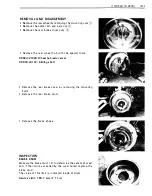
R E M OVAL 

• 

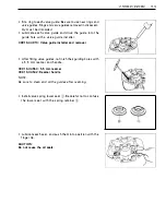
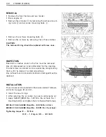
R e move  the  fro nt  fe n d e r   a n d   rea r  fen d e r .  

• 

D r a i n  e n g i n e   o i l .  

• 

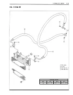
Re move the o i l  coo l e r  

CD 

by remov i n g  t h e  o i l  hose m o u nt­

i n g   bolts 

a n d   oil  c oo l e r   m o u nt i n g   bolts 

@ .  

• 

Re move  t h e  o i l   h o s e   m o u nt i n g   bolts 

@. 

• 

Re move  the  o i l   h o s e   b y   r e m ov i n g   t h e  o i l   hose  c l a m p s .  

CAUTION : 

The  removed  0-ring  should  b e   replaced  with  new  ones . 

I N S PECT I O N  

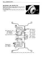
R o a d   d i rt  o r  trashes  stu c k   t o   t h e   f i n s   m u st  b e   removed . 
U s e   o f   c o m p ressed  a i r   i s   rec o m me n d e d   for  t h i s   c l ea n i n g . 
F i n s   bent  d o w n   or  d e nted  c a n   be  re p a i red  by  stra i g h te n i n g  

t h e m   with  t h e   b l a d e   of  a  s m a l l   screwd rive r .  
A n y  o i l  hose fo u n d  i n  cracked c o n d it i o n  o r  d a m ag e d  m u st  b e  

r e p l a ced . 

I N STA L LAT I O N  

T h i s  o i l  cooler is t o  be i n sta l l ed  i n  t h e  reverse order o f  removal ,  

a n d   refer  t o  pages  2 6   a n d  4 2 .  

• 

I nsta l l  t h e  n e w   0-ri n g s . 

• 

After  i n stal l i ng  t h e   o i l   c o o l e r ,   be  s u re  to  a d d   e n g i n e   o i l . 

• 

A p p l y   S U Z U K I   B O N D   N o .  1 2 0 7 8   to  t h e   o i l   hose  N o .   1 
mounti n g  bolts

® 

and tighte n them to the specified torq u e .  

99 1 04-3 1 1 40 :   S U Z U K I   B o n d   N o .   1 20 7 B   ( For  U . S . A . )  
99000-3 1 1 40 :   S U Z U K I   Bond  N o .   1 20 7 8   (For  the  others) 

Tightening  torque :  9  - 1 0  N · m 

( 0 . 9   - 1 . 0  kg-m,  6 . 5   - 8 . 0   lb-ft ) 

Summary of Contents for LT-4WD 1990

Page 1: ...lllllllllllllllllllllllllll 1111 11 Ill 1111111111111 1111111IIIII 1 1 II11111111 99500 42059 01 E ...

Page 2: ...to standard specifications is the main subject matter of this manual However the LT 4WD machines distributed in your country might differ in minor respects from the standard specification and if they do it is because some minor modifica tions which are of no consequence in most cases as far as servicing is r oncerned had to be made to comply with the statutory requirements of your country This man...

Page 3: ...VI EW O F SUZU KI LT 4WDH 87 MODEL R IGHT SI D E L E FT SI D E ...

Page 4: ...FERENTIAL GEARS FUEL AND LUBLICATION SYSTEM ELECTRICAL SYSTEM CHASSIS SEARVICING INFORMATION LT F4WDH APPENDIX LT 4WD AND LT F4WD LT 4WDJ AND LT F4WDJ LT 4WDK AND LT F4WDK 89 MODEL LT 4WDL AND LT F4WDL 90 MODEL LT 4WDM AND LT F4WDM 91 MODEL LT F4WDXM 91 MODEL LT F4WDV W AND LT F4WDXV W 97 AND 98 MODELS ...

Page 5: ......

Page 6: ... CONTENTS VIN AND SERIAL NUMBER LOCATIONS 1 1 FUEL AND OIL RECOMMENDATIONS 1 1 BREAKING IN PROCEDURE 1 1 S PECIAL MATERIALS 1 2 PRECAUTIONS AND GENERAL INS TRUCTIONS 1 5 S PECIFICATIONS 1 6 ...

Page 7: ...owing chart SINGLE GRADE MULTIGRADE TEMP D I F F E R E N T I A L G EA R O I L Use SEA 90 hypo id gear oil which is rated GL 5 under API classification system If you operate the vehicle where ambient temperature is below ooc 32 F use SAE 80 hypoid gear oil B RA K E F LU I D Specification and SAE J 1 703 classification DOT 3 or DOT 4 99000 23021 SUZU K I B RAKE F LU I D Not available i n U S model B...

Page 8: ...t Page Throttle lever 2 20 Brake pedal shaft and rod lin k 2 20 Front brake anchor and cup 2 20 Oil seals 3 50 6 9 Recoil starter spiral spring 3 80 shaft and ratchet 0 ring Propeller shaft and u nivaersal 4 37 joint Wheel cylinder dust seal 7 12 In ner spline of hub 7 14 Front wheel h ub bearing 2 20 7 22 Steering shaft lower portio n 7 31 Dust seals 7 31 7 32 Steerin g shaft holer and dust 7 32 ...

Page 9: ...AD LOCK SUPER 1305 99000 32100 THREAD LOCK SUPER 1322 99000 32110 Part Page Magneto lead wire gro m met 3 48 Matin g surface of rig ht 3 58 crankcase Blow by gas pipe 3 58 Mating surface of rear brake 7 40 panel Wheel h ub bolts 7 41 Brake fluid front Starter clutch bolts 3 47 Oil pump case securing screw 3 48 Cam sprocket bolts 3 75 Magneto rotor nut Differential bevel gear hub bolts Propeller sh...

Page 10: ...LICON E GREASE 99000 25100 G E N E RA L I N F O R M AT I O N 1 4 Part Secondary driven outpu t shaft nut Secondary driven outpu t shaft Drive gear nut and front drive output yoke n u t Differential gear shaft 2nd drive gear Page 4 7 4 8 4 11 4 19 3 53 Sub transmission cam stopper 3 63 bolt Drive shift cam stopper bolt 3 65 Drive shift cam plate bolt 3 65 Gearshifter m o u n ting bolt 3 66 Suspensi...

Page 11: ...mended oils When more than 2 persons perform work together pay attention to the safety of each other After the reassembly check parts for tighteness and operation Treat gasoline which is extremely flammable and highly explosive with greatest care Never use gasoline as cleaning solvent Warning Caution and Note are included in th is manual occasional ly describing the fol lowing contents WARNING The...

Page 12: ...arburetor M I KUN I VM24SS single Air cleaner Polyurethane foam element Starter system E lectric and recoiI starter Lubrication system Wet sump T RA N SM I S S I O N Clutch Wet mu lti plate automatic centrifugal type Transmission 5 forward constant mesh 1 reverse with 3 sub transmission Gearshift pattern Forward All up foot lever operated Reverse Hand lever operated Primary reduction 3 250 65 20 S...

Page 13: ...ped spring preload 5 way adjustable Steering angle I nside 43 48 Outside 29 1 2 Trail 1 6 mm 0 6 in Turning rad ius 2 7 m 8 9 ft Front brake I nterna l expand ing hydrau l ica l ly operated Rear brake I nterna l expanding mechanica l ly operated Front tire size 22 x 8 00 1 0 x2 Rear tire size 25 x 1 2 00 1 0 x2 Front wheel travel 85 mm 3 3 in Rear wheel travel 95 mm 3 7 in CAPACITIES Fuel tank inc...

Page 14: ...i J V l VE CLE fl CE 5 E GI E LJ TI G fllJBBER BLJ fl 6 l flK PLLJG 7 FLJEL l I E 7 Jiflfl JiTL E C Bl E 8 l GI E ll LE I EEl 8 E GI E ll D IL Fll JiER 9 lJIFFEflE TI L Gl fl JL 10 Cl LJTCfl 11 Tlfll 2 11 Bfl KE I ElJ l l EVEfl 2 1 Bfl KE FLLJID 13 Bfl Kl fi E 14 Bfl KE fi E 15 JiEEfli G 2 16 LJ PE I 16 Cfi S I NLJJiS D B Lji 17 CJE l R l L liBfli TI S ...

Page 15: ...ding or months wh ichever 100 mi les comes first or 1 month Battery I Air cleaner element E ngine nuts and bolts T Valve clearance I E ngine mounting rubber bush Every 1 000 km Every 2 000 km 600 m iles 1 200 mi les or 3 months or 6 months I c T I Replace every 4 years I Spark plug Replace every 6 000 km 4 000 miles or 1 8 months I Fuel lines Replace every 4 years Throttle cable I I E ngine id le ...

Page 16: ...X level line To deter mine state of change check specific gravity with hydrometer 09900 28403 Standard specific gravity Hyd rometer A specific gravity reading of 1 22 at 20 C or under means that the battery needs recharging CAUT I O N D o not charge the battery wh ile connected to the vehicle Charging the battery while connected into the circuit may damage the regulator rectifier or other componen...

Page 17: ...the polyurethane foam element from the element frame by loosening the screw F i l l a washing pan of a proper size with non flammable cleaning solvent I mmerse the ele ment in the cleaning solvent and wash it clean Squeeze the cleaning solvent out of the washed element by pressing it between the palms of both hands I mmerse the element in motor oi I and squeeze the oil out of the element leaving i...

Page 18: ...8 0 lb ft torque 6 mm 7 1 1 N m 0 7 1 1 kg m 5 0 8 0 lb ft When instal l ing the cylinder head cover apply SUZU K I Bond No 1 207B 1 2 1 5 to the mating surface 99 1 04 31 1 40 SUZU K I Bond No 1 207 B For U S model 99000 3 1 1 1 0 SUZU K I Bond No 1 2 1 5 For other models Tighten the cyl inder head cover bolts to the specified torque Refer to page 3 77 Exhaust p ipe nuts and muffler bolts Tighten...

Page 19: ...ead Center T D C of the com pression stroke o Remove the seat rear carrier and rear fender Refer to page 3 4 Remove the spark plug and valve inspection caps CD Remove the T D C plug Remove the recoi I starter Refer to page 3 1 3 Rotate the magneto rotor to set the piston at T D C of the compression stroke by tu rning the starter cup Rotate the rotor unti l the T line on the rotor is aligned with t...

Page 20: ...ve the six rubber bushes After install ing the new rubber bushes remount the engine and tighten the engine mounting bolts to the specified torque FRONT Tighte n i ng torqu e D ia m 1 2 m m 60 70 N m Length 300 m m 6 0 7 0 kg m J 43 5 52 0 lb ft D ia m 1 0 m m 80 95 N m Length 1 90 m m 8 0 9 5 kg m 58 0 68 5 lb ft 60 70 N m D ia m 1 0 m m 6 0 7 0 kg m 43 0 50 5 lb ft ...

Page 21: ...t porcelain is wh itish in appearance replace with colder one FOR E 03 Standard Cold type N G K D7EA D8 EA N D X22ES U X24ES U FOR E 24 I 0 6 0 7 m m 0 024 0 028 i n Standard Cold type R type spark plug N G K D7EA D8EA FOR E 28 Standard Cold type N G K D R7ES D R8ES L N D X22ES R U X24ES R U FUEL LINES Inspect every 1 000 km 600 miles Replace Every 4 years I nspect the fuel lines and connections f...

Page 22: ...al 200 km 1 00 miles and Every 2 000 km 1 200 miles Idling adjustment NOTE Make this adjustment when the engine is hot Turn in the pilot screw CD until it bottoms NOTE Be careful not to overtighten the screw F rom that position turn out the pi lot screw 2 3 8 turns Connect a tachometer Start up the engine and set its speed between 1 350 and 1 450 r min by turning throttle stop screw Turn in or out...

Page 23: ...6 51b ft Start up the engine and allow it to run for several seconds at idl ing speed Shut down the engine and wait about one minute Then check the oil level in the oi l level window The veh icle must be in a level position for accurate measurement I f the level is below the upper line add oil u ntil the level reaches the upper I ine Engine oil filter Replace the oi l filter in the fol lowing mann...

Page 24: ...en reassembling the o i l filter make sure to check that the oil filter is installed as shown above If the filter is installed i mproperly serious engine damage may result DIFFERENTIAL GEAR OIL I nspect I nitial 200 km 100 miles and Every 2 000 km 1 200 m iles Replace Every year To change the differential gear oil locate the vehicle on level ground and carry out the fol lowing steps Use SEA 90 hyp...

Page 25: ...hat position loosen the release screw 0 1 8 rotation and tighten the lock nut while holding the release screw I nstall the clutch adjuster cap bolt properly TIRES I I nspect Every month I nspect the tires for wear and damage Check the tire tread depth as shown Replace a bad ly worn or damaged tire A tire with its tread worn down to the limit in terms of thread depth must be replaced Tread depth se...

Page 26: ...ol lows NOT E First adjust the brake pedal and next adjust the brake lever Brake pedal Remove the right rear mud guard Level the brake pedal with the footrest This is effected by turning the adjusting bolt CD Be sure to tighten the lock nut good and hard after setting the bolt When adjusting the travel of brake pedal adjust the free travel to 20 30 m m 0 8 1 2 in by turning the adjusting bolt Be s...

Page 27: ...000 23021 SEA J 1703 DOT 3 or DOT 4 SUZU K I Brake fluid Not available in U S model Bleeding air from the brake fluid circuit Air trapped in the fluid circu it acts like a cushion to absorb a large proportion of the pressu re de veloped by the master cylinder and thus interferes with the ful l braking performance of the drum brake The presence of air is indicated by spongi ness of the brake lever ...

Page 28: ...and squeeze the lever ful l y without releasing it Loosen the bleeder valve by turning it a quarter of a turn or so that brake fluid runs into the receptacle th is wil l remove the tension of the brake lever causing it to touch the handlebars grip Then close the valve pump and squeeze the lever and open the valve Repeat this process u ntil the fl uid flowing into the receptacle no longer contains ...

Page 29: ...hicle is equ ipped with brake l ining wear limit indicator on the brake panel At the condi tion of normal lining wear an extended line from the index mark on the brake camshaft should be with in the range embossed on the brake panel with the brake on To check wear of the brake lining follow the steps below First check if the brake system is properly adjusted While operating the brake check to see ...

Page 30: ...e seat M easu re t h e d istance A and B i n i l l ustrati o n o f fr o nt w he e ls with a t o e i n gauge as sh o wn i n i l l ustrati o n and cal icu late the d iffe r ence between A and B T oe in 75 kg l th 165 l b s loa 11 19 m m 0 43 0 75 i n I f the t o e i n is o ff the specificati o n bri n g it i nto the specified ran g e Refer to page 7 34 SUSPENSION I I nspect Every 2 000 km 1 200 m i ...

Page 31: ...Upper and Lower Front brake panel bolt 1 8 28 1 8 2 8 1 3 0 20 0 j Front axle nut 85 1 1 5 8 5 1 1 5 6 1 5 83 0 F ront wheel set nut 45 65 4 5 6 5 32 5 47 0 Air bleeder valve 6 9 0 6 0 9 4 5 6 5 Steering knuckle arm pinch bolt 44 66 4 4 6 6 32 0 47 5 Upper Lower j Shock absorber mounting bolt 40 60 4 0 6 0 29 0 43 5 Steering knuckle arm end pinch bolt 40 60 4 0 6 0 29 0 43 5 Steering knuckle arm p...

Page 32: ...PE R I O D I C M A I N TE N AN C E AN D TU N E U P P R O C E DU R ES 2 1 8 STEERING AND FRONT SUSPENSION CD Ac B c VIEW A VIEW B ...

Page 33: ...2 1 9 P ER I O D I C M A I N T E N AN C E AN D TU N E U P P R O C E DU R ES ...

Page 34: ... to rust with motor oil or grease Before lubricating each part clean off any rusty spots and wipe off any grease oil dirt of grime WAR N I NG Be careful not to apply too much grease to the brake cam shaft I f grease gets on the linings brake slippage wil l result Q Steering sha ft holder Speedometer cable Choke cable B ra ke l ever holder and cabl e T hrottl e c ab le a n d holder T h rottle le v ...

Page 35: ......

Page 36: ...NE REASSEMBLY 3 50 OIL SEALS 3 50 CRANKSHAFT 3 50 SECONDARY DRIVEN OUT PUT SHAFT 3 51 TRANSMISSION 3 52 GEARSHIFT CAM AND FORK 3 55 CRANKCASE 3 57 REVERSE SWITCH AND REVERSE CAM STOPPER BOLT 3 59 SPEEDOMETER DRIVE GEARB0 3 59 NEUTRAL SWITCH 3 59 STARTER CLUTCH AND MAGNETO ROTOR 3 60 SUB TRANSMISSION 3 61 SUB TRANSMISSION GEARSHIFT CAM AND FORK 3 63 MAGNETO COVER 3 64 DRIVE SHIFT CAM 3 64 OIL PUMP ...

Page 37: ...or a few seconds with starter and read the highest gauge indication as the compression of the cylinder CD 0991 5 645 1 0 Compression gauge 099 1 5 632 1 0 Adaptor Compression pressu re Standard Limit 1 000 1 400 kPa 800 kPa 1 0 14 kg cm2 142 1 99 psi 8 kg cm2 1 1 4 psi A low compression pressu re may indicate any of the fol lowing malfunctions Excessively worn cylinder wal l Worn piston or piston ...

Page 38: ... 09900 26005 E ngagement r mi n Standard Tolerance Engine tachometer Not avai lable in U S model 2 000 r m in 200 r min I f the engagement r min does not coincide with the standard range inspect the following items for any abnormal ity Page Clutch shoes 3 45 Clutch wheel 3 45 Clutch drive and driven plates 3 44 3 45 CLUTCH LOCK UP INSPECTION Perform this inspection to determine if the clutch is en...

Page 39: ...over 3 1 4 Camsh aft 3 1 4 Cy l i nder head 3 1 5 Cyl i nder 3 1 5 Starter m oto r 3 1 6 P i ston 3 1 6 R everse swi tch 3 25 O i l su m p fi lter 3 57 N eutra l cam stopper b o l t 3 25 P ro pe l ler sh aft 3 9 E N G I N E R I G H T S I D E See page O i l fi lter 2 8 C l utch cover 3 1 6 C l utch re l ease m ech a n ism 3 1 7 C l utch shoe 3 1 7 P r i m a ry d rive gea r 3 1 7 O i l p u m p asse ...

Page 40: ... clean the engine with a su itable cleaner The procedure of engine removal is sequentially explained in the following steps Remove the seat by pul l ing the lever CD Remove the rear carrier Remove the fou r bolts Remove the mud flap mounting brackets right and left Remove the rear fender E N G I N E 3 4 ...

Page 41: ...lock Remove the rear wheels right and left by loos ening nuts Remove the rear suspensions and suspension arms right and left by removing bolts and nuts NOTE To remove the right suspension arm it becomes necessary to d isconnect the rear brake cable CD ...

Page 42: ... lts Disc o nnect the lead wi r e and r emove the r ea r c o nta i ne r e Rem o ve t h e f o u r b o lts andr em o ve the p late L oo sen t h e b o lt CD and r em o ve the bolts r ig h t a nd left and then r em o ve the m uffle r backw a r ds E N G I N E 3 6 ...

Page 43: ...Loosen an air cleaner intake pipe clamp screw G Remove the three air cleaner mounting bolts Sl ide the clip and disconnect the blow by gas hose Take out the air cleaner Remove the three bolts and pu l l out the sub transmission lever transmission lever and reverse lever 0 ...

Page 44: ...t the speedometer cable Disconnect the lead wires Neutral switch Reverse switch Charging Pick up Power source Remove the universal joints right and left with the special tool 09930 301 02 Slid ing shaft 09924 2 1 9 1 0 Wheel hub remover set E N G I N E 3 8 ...

Page 45: ...tor lead CD and ground lead Pu l l out the spark plug cap Remove the two exhaust pipe clamp nuts Pu l l out the cotter pin and disconnect the gearshift lever cable Remove the engine mou nting nuts Remove the two bolts and then remove the left side frame bridge with engine mounting bolt Use both hands and remove the engine from the frame removing it from the left side ...

Page 46: ...nting bolts I TEM N m kg m l b ft 60 72 6 0 7 2 43 5 52 0 80 95 8 0 9 5 58 0 68 5 Tighten the propel ler shaft coupl ing bolts to the specified torque Tightening torque N m kg m l b ft 40 50 4 0 5 0 29 0 36 0 N OT E E N G I N E 3 1 0 The engi ne mounting nuts are self lock nut O nce the nut has bee n removed it is no longer of any use Be sure to use new nuts and tighten them to the specified torqu...

Page 47: ...mission lever al ign the groove CD with sl it Tighten the exhaust pipe clamp nuts to the specified torque Tightening torque N m kg m 9 1 2 0 9 1 2 lb ft 6 5 8 5 Tighten the muffler connection bolt and mounting bolts to the specified torque Tighteni ng torque ITEM N m kg m lb ft 1 8 23 1 8 2 3 1 3 0 16 5 1 8 28 1 8 2 8 1 3 0 20 0 ...

Page 48: ...b ft CD 40 60 4 0 6 0 29 0 43 5 50 70 5 0 7 0 36 0 50 5 T ighten t h e r ea r w h eel set nuts t o the specified t or q ue Tihgtening torque I T E M N m kg m l b ft 45 65 4 5 6 5 32 5 47 0 e T ighten t h e rear carrier b o lts and t o t h e specified t or que Tightening torque IT E M N m kg m lb ft 30 40 3 0 4 0 2 1 5 29 0 20 30 2 0 3 0 1 4 5 2 1 5 I E N G I N E 3 1 2 ...

Page 49: ...move the recoil starter assembly 09900 00302 01 1 T type box wrench 8 mm Not available in U S model Remove the inspection plug Rotate the recoil cup u ntil the T l ine on the rotor is aligned with the index mark on the crankcase N OT E When removing the cylinder head cover piston must be at top dead center on com pression stroke ...

Page 50: ...cyl inder head c o ve r N OT E When removing the cyl inder head cover do not remove the conically recessed top bolts Rem o ve the ca mshaft end cap CD F latten the l o ck washer and rem o ve the two camshaft s p r o cket bolts Rem o ve the ca mshaft and sp ro cket NOT E Do not drop camshaft drive chain pin and sprocket into the crankcase E N G I N E 3 1 4 ...

Page 51: ... t s t h e n d et acht h e cyl ind er h e ad NOT E I f i t i s d ifficu lt t o remove the cyl inder head gently pry it off while tapping the finless portion of the cyl inder head with a plastic hammer Be careful not to break the fins R e m o v e t h e cam cha i n guid e R e m o v e t he cy l i nd er bas e n u t s R e m o v e t h e cy l i nd er CAUT I O N I f tapping with plastic hammer i s necessa...

Page 52: ... piston pin ci rclip from dropping into crankcase and then remove the piston pin circl ip with long nose pl iers Remove the piston pin with the special tool 09910 34510 Piston pin pul ler Remove the starter motor Remove the clutch cover E N G I N E 3 1 6 ...

Page 53: ...move the clutch shoe assembly 0991 0 201 1 5 Conrad holder NOTE Clutch shoe nut has left hand thread Do not attempt to disassemble the clutch shoe it is not serviceable To prevent the conrad small end from getting into the conrad holder insert the piston pin to the conrad small end Remove the one way clutch inner race one way clutch washer primary drive gear bearings circl ips and spacer ...

Page 54: ...al tool and then remove the release plate 0991 0 201 1 5 Conrad holder NOTE To prevent the conrad small end from getting into the conrad holder insert the piston pin to the conrad small end Remove the clutch sleeve hub nut with the special tool 09920 53730 Clutch sleeve hub holder Remove the concaved washer clutch sleeve hub drive plates driven plates and pressure disc E N G I N E 3 1 8 ...

Page 55: ... assembly Remove the spacer and washer Remove the E ring and oil pump driven gear NOTE When removing the oil pump driven gear be careful not to lose the pin Remove the oil pump drive gear j Remove the oi l pump with the special tool 09900 09003 I mpact driver set ...

Page 56: ... gea rs h i ft i n g shaft o R e m ove the ca m sto pper spri n g w i t h l o n g nose p l iers G R e m ove the b o l t a nd washer then remove the ca m sto pper R e m ove the b o l t J s h i ft cam stopper p l ate p i ns and sh i ft ca m d r i ve p i n reta i ne r f o C1 E N G I N E 3 20 ...

Page 57: ... 201 1 5 Conrad holder NOTE To prevent the conrod sma l l end from getting i nto the conrod holder insert the piston pin to the conrod small end Remove the starter cup Remove the magneto cover Pul l out the sub transmission shift fork shafts No 1 CD and No 2 Remove the sub transmission shift forks No 1 and No 2 ...

Page 58: ... idle gear Remove the sub transm ission d rive sliding dog J and driven sliding dog Remove the circl i p w ith the specia l tool and then remove the washer a nd sub trans m ission drive No 1 gear j Remove the circ l i p with the special too l and then remove the washer and sub transmission driven No 1 gear Jl 09900 061 07 Snap ring pl iers E N G I N E 3 22 ...

Page 59: ...washer Remove the sub transmission shift cam stopper spring R emove the bo lt and then remove the sub transmission shift cam stopper j and washer Remove the washer and pul l out the sub transm ission sh ift cam Pu l l out the shaft and remove the starter idle gear j and spacer ...

Page 60: ...avai lable i n U S model Screw in the rotor remover attachment u nt i l t h e left su rface o f t h e cran kshaft seats the attachment 09930 3 1 920 Rotor remover set I nstal l the rotor remover correctly and remove the rotor NOT E Do not hit the rotor with a hammer Remove the key CD Pu l l out the sta rter clutch gear E N G I N E 3 24 ...

Page 61: ...3 25 E N G I N E Remove the cam chain Remove the neutral switch CD 0 ring Pin Spring Remove the reverse lever bracket Remove the reverse switch and reverse cam stopper bolt ...

Page 62: ...lts for right side NOT E Be sure to remove a bolt Separate the crankcase with the special tool 09920 131 20 Crankcase separating tool NOTE F it the crankcase separating tool to the right side so that the tool plate is paralleled with the end face of the crankcase Pul l out the shift fork shafts No 1 and No 2 E N G I N E 3 26 ...

Page 63: ... cam I and then take out the reverse shift fork and shift forks Remove the washer and the reverse idle gear Remove the reverse idle gear shaft I bush and spacer 0 Remove the reverse sliding dog I and then remove the cou ntershaft and driveshaft assem blies ...

Page 64: ...bly by tapping with a plastic hammer from the opposite side Draw out the rear final d riven shaft assembly by tappi ng with a plastic hammer from the opposite side Remoe the cran kshaft from the crankcase with the special too l I 09920 1 3 1 20 I Crankshaft remover Cra nkcase separati ng o l 1 E N G I N E 3 28 ...

Page 65: ... be restored to the original location during assembly Pu I I out the de compression shaft CD Remove the rocker arm shaft set bolts and puI I out the rocker arm shafts with a pi iers CAUT I O N Use a new gasket on the set bolt to prevent o i l leakage The exhaust rocker arm can be distinguished from that of the intake by the de compression shaft contacting surface for exhaust Remove the cam chain t...

Page 66: ...the valve retainer inner spring and outer spring Pu ll out the valve from the other side Remove the oil seal using long nose pliers Take off the spring seat NOT E Removal of valves completes ord inary d isas sembli ng work I f valve gu ides have to be removed for replacement after inspecting related parts carry out the steps shown in valve g u ide servicing E N G I N E 3 30 ...

Page 67: ...d 09900 20205 1 1 966 1 1 984 m m 0 47 1 1 0 47 1 8 in Micrometer 0 25 mm R O C KER A R M I D When checking the valve rocker arm the inside diameter of the valve rocker arm and wear of the camshaft contacting surface should be checked Standard 1 2 000 1 2 01 2 mm 0 4724 0 4729 in 09900 20605 Dial cal ipers Not available in U S model CYL I N D E R H EAD D I STO RT I O N Decarbon combustion chamber ...

Page 68: ...09900 20606 Dial gauge 1 1 00 mm VALVE HEAD RADIAL RUNOUT Place the dial gauge at right angles to the valve head and measure the valve head radial runout If it measures more than limit replace the valve Service Limit 0 03 mm 0 001 in VALVE GUIDE VALVE STEM CLEARANCE Measure the clearance in two directions X and Y perpendicular to each other by rigging up the dial gauge as shown If the clearance me...

Page 69: ... 0 2 1 50 0 2 1 56 i n EX 5 445 5 460 mm 0 2 1 44 0 2 1 50 in VALVE GUIDE SERVICING Remove the valve guide with the valve guide remover 0991 6 4491 0 Valve guide remover Re finish the valve guide holes in cyl inder head with a 1 1 3 mm reamer CD and handle 0991 6 34561 1 1 3 mm reamer 0991 6 34541 Hand le Fit a ring to each valve guide Be sure to use new rings and valve guides Rings and valve guid...

Page 70: ...he lower seat with the spring retainer Lubricate each seal and drive them into position with the finger tip CAUT I ON Do not reuse the oil seals VALVE AND SEAT CONDITION VALVE SEAT WIDTH Coat the valve seat with prussian blue uniformly Fit the valve and tap the coated seat with the valve face in a rotating manner in order to obtain a clear i m pression of the seating contact I n this operation use...

Page 71: ...00 1 0 Sol id pi lot EX For other models 0991 6 2 1 1 1 0 Valve seat cutter set 0991 6 24900 Valve seat cutter set 0991 6 206 1 0 Cutter N 1 2 1 0991 6 20620 Cutter N 1 22 0991 6 249 1 0 Cutter N 2 1 2 0991 6 24935 Cutter N 608 0991 6 24480 Sol id pi lot N 1 40 5 5 0991 6 24450 Sol id pilot N 1 00 1 0 N OTE T he valve seat contact area must be inspected after each cut 1 I nsert with a slight rotat...

Page 72: ...onds of engine operation 5 Clean and assemble the head and valve compo nents Fill the intake and exhaust ports with gasoline to check for leaks If any leaks occur inspect the valve seat and face for burrs or other things that could prevent the valve from sealing WAR N I NG A lways use extreme caution when hand l ing gaso l i ne NOT E Be sure to adjust the valve clearance after reassembl ing the en...

Page 73: ... 5 7 20 3 lbs 1 28 in OUT E R 1 7 3 21 3 kg 36 0 m m 38 1 47 0 lbs 1 42 in REASSEMBLY I nsert the valve with thei r stems coated with SUZ U K I M O LY PASTE al l around and along the ful l stem length without any break Simi larly oi l the lip of the stem seal 99000 251 40 SUZU K I Moly paste CAUT I ON When inserting each valve take care not to damage the l i p of the stem seal I nstall the valve s...

Page 74: ...ng in reduced output power The l i m it of cam wear is specified for both intake and exhaust cams in terms of cam height 8 which is to be measu red with a micrometer Re place the camshaft if fou nd it worn down to the limit 09900 20202 M icrometer 25 50 mm Cam height Height 8 Service Limit Intake cam 33 870 mm 1 3335 in Exhaust cam 33 1 70 mm 1 3059 in CAMSHAFT JOURNAL WEAR Determi ne whether each...

Page 75: ...over tightening torque Tightening torque 09900 22301 9 1 1 N m 0 9 1 1 kg m 6 5 8 0 lb ft Plastigauge Not available in U S model If the camshaft journal oil clearance measured exceeds the limit measure the outside diameter of camshaft Replace either the cylinder head set or the cam shaft if the clearance is incorrect 09900 20205 Camshaft journal O D Micrometer 0 25 m m 2 1 959 21 976 m m 0 8645 0 ...

Page 76: ... straightedge exceeds the l imit replace the cyl inder Service Limit 0 05 mm 0 002 in CYLINDER BORE Measure the cyl inder bore diameter at six places If any one of the measu rements exceeds the limit overhaul the cylinder and replace the piston with an oversize or replace the cyl inder 09900 20508 Cylinder gauge set Service Limit 66 090 mm 2 6020 in PISTON DIAMETER Using a micrometer measure the p...

Page 77: ...1 st and 2nd rings I f any of the clea rances exceeds the limit replace both piston and piston rings 09900 20803 Thickness gauge Piston ring groove clearance Piston ring Service Limit 1 st 0 1 80 mm 0 007 1 in 2nd 0 1 50 mm 0 0059 in Piston ring groove width Piston ring Standard 1 st 1 01 1 03 mm 0 0398 0 0406 in 2nd 1 22 1 24 m m 0 0480 0 0488 i n Oi l 2 01 2 03 mm 0 0791 0 0799 in Piston ring th...

Page 78: ...n 7 5 mm 0 30 in Vernier calipers Service Limit 0 70 mm 0 028 in Thickness gauge The following two types of oversize piston rings are used They bear the following identification numbers Piston ring 1 st 2nd 0 5 mm O S 50 50 1 0 mm O S 1 00 1 00 Oversize oil rings The following two types of oversize oil rings are used They bear the fol l owing identification marks S I Z E MA R K Standard N I L 0 5 ...

Page 79: ...1 in 1 5 980 mm 0 629 1 in CON ROD S MALL EN D I D Using a caliper gauge measure the conrad small end inside d iameter Service Limit 1 6 040 mm 0 63 1 5 in I f the conrad smal l end bore inside d iameter ex ceeds the limit replace conrad CON ROD DEFLECTION AN D CON ROD B I G END S I DE C LEARAN CE Wear on the big end of the conrad can be estimated by checking the movement of the sma l l end of the...

Page 80: ...shown with the two end journals resting on the blocks Position the dial gauge as shown and rotate the crankshaft slowly to read the runout Correct or replace the crankshaft if the runout is greater than the l imit A 0 05 m m 0 002 in Service Limit B 0 08 mm 0 003 in CLUTCH DRIVE PLATE Measure the thickness and claw width of each drive plate with vernier cal ipers Replace drive plates found to have...

Page 81: ...ernier cal i pers Service Limit 27 5 mm 1 08 in NOTE Clutch spring must be changed as a set and never i ndividually CLUTCH SHOE I nspect the shoes visually for chips cracking u neven wear and burni ng and check the depth of the grooves on the shoes If there is no groove at any part of the shoes replace them as a set NOTE Clutch shoes must be changed as a set and never individually CLUTCH WHEEL I n...

Page 82: ...race turns both directions or is locked replace the one way clutch assembly with a new one CLUTCH RELEASE MECHANISM R E MOVA L Remove the cl utch release outer guide release bal l inner guide and washer Remove the lock nut and pul l out the clutch release CLUTCH RELEASE BALL Rotate the bal ls by hand to inspect for an ab normal noise and a smooth rotation Replace the clutch release bal l if there ...

Page 83: ...al led in the proper direction as shown in Fig NOTE When installing the starter clutch to the rotor face the cut of the cage to the rotor Apply engine oi l to the starter clutch Apply TH R EAD OCK SUPE R 1 303 to Al len bolts Tighten them to the specified torque whi le holding the rotor by using the 29 mm off set wrench 99000 32030 Tightening torque Thread Lock Super 1 303 23 28 N m 2 3 2 8 kg m 1...

Page 84: ...ounting bolts 99000 32050 Thread Lock 1 342 NOTE Bond No 12078 1215 should be appl ied to the groove of magneto lead wire grommet 99 1 04 31 1 40 SUZUK I BON D No 1 207B For U S model 99000 31 1 1 0 SUZ U K I BON D No 1 2 1 5 For other models OIL PUMP CAUT I ON The o i l pump case securing screw i s applied with SUZ U K I T H R EAD LOCK S UPER 1303 I f an attempt is made to overhaul the o i l pump...

Page 85: ...or the gear shifting fork should be replaced by measu ring the thickness and groove width 09900 20803 Thickness gauge Item Standard Shift fork 0 1 0 0 30 mm to groove 0 004 0 0 1 2 in clearance Limit 0 50 mm 0 020 i n 09900 201 01 Vernier calipers Standard Standard Shift fork groove width Transmission No 1 No 3 No 2 Sub transmission No 1 No 2 Reverse 4 50 4 60 mm 0 1 77 0 1 81 in 5 45 5 55 0 2 1 5...

Page 86: ... Apply engine o i l t o each running and sl iding part before reassembling OIL SEALS Apply grease to the lip of oil seals 99000 25030 For U S model 99000 2501 0 SUZUK I Super G rease A For other models NOT E Replace the oi l seals with new ones every d isassembly to prevent oil leakage CRANKSHAFT E N G I N E 3 50 CD Bea r i ng R O i l pu m p d ri ve ge a r Bearing P i n Cra n k s haft R C ra n k p...

Page 87: ...case by using the special tools 0991 0 3281 2 Cran kshaft instal ler CAUT ION N ever fit the crankshaft into the crankcase by striking it with a plastic hammer A lways use the special tool otherwise crank shaft al ignment accuracy w i l l be affected SECONDARY DRIVEN OUT PUT SHAFT When installing the secondary driven out put shaft assembly be sure to install the C ring CD for the rear side bearing...

Page 88: ...ashers and circl ips CAUTI ON Never reuse a circl ip After a circlip has been removed from a shaft the removed circl ip should be d iscarded and a new circlip must be installed When installing a new circl ip care must be taken not to expand the end gap larger than req u ired to slip the circl ip over the shaft After install ing a circl ip always insure that it is completely seated in its groove an...

Page 89: ... SUPE R 13338 NOT E After mounting the 2nd d rive gear check that TOP drive gear spins smoothly by moving it w ith your fingers This procedure may be performed only twice before shaft replacement is required CD R everse sl id i ng dog R everse driven ge a r Low driven gear 4th driven gear 3rd driven gear Top driven gear J 2 n d d riven gear D ri veshaft Cou nte rshaft Low drive gear R everse d ri ...

Page 90: ...e shaft insert lock washer No 2 into the drive shaft and tu rn and fit it into the groove Then fit the lock washer No 1 in the lock washer No 2 e When insta l l ing a circl ip pay attention to the direction of the circl ip Fit it to the side where the thrust is as shown in the figure with the rounded side against the gear surface E N G I N E 3 54 Thrust kl ...

Page 91: ... the ne to nn CD Gea rsh ifter f g shaft r i Gearsh l tm s 1de 61 E ng m e Gearsh ift l ever e r bolt R everse ca m sto pp R everse sw itch J h ft ca m R everse gears I h ift lever j R everse g ars E n g i n e s1de h ift fork R everse gears 1 G ea rsh i ft fork N o 2 G ea rsh ft for o o haft N o 1 lti G ea rsh 1 ft 1 n g Y gea r Shift ca m d nve Gearsh ift c a m N eutra l SW itch r l Cam stopper 3...

Page 92: ...sta l l the reverse sl iding dog Fit the reverse gearsh ift fork j into the gear shifting groove and reverse gearshifting groove Insta l l the gearshifting fork shafts NOT E Four kinds of gear shifting forks are used They resemble each other very closely in external appearance and configuration Q Gearshift fork No 1 Gearshift fork No 2 Gearshift fork No 3 j Reverse gearshift fork E N G I N E 3 56 ...

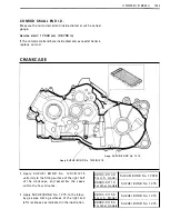
Page 93: ...ide of the spacer should face to the reverse idle gear CD After the reverse id le gear has been fitted confirm that reverse gear change is normal while shifting the gearshift into the neutral position If reverse gear change is not obtained it means that assembly of reverse parts is incorrect I f this is the case disassemble and trace the mistake CRANKCASE When reassembling the crankcase pay attent...

Page 94: ...assemble the cases within few minutes 99 1 04 3 1 1 40 SUZ U K I BOND No 1 207 B For U S model 99000 31 1 1 0 SUZU K I BON D No 1 21 5 For other models Apply SUZ U K I BON D No 1 2 1 6 to the blow by gas pipe mating surfaces of the right and left crankcase as indicated in the figure 991 04 31 1 60 SUZU K I BON D No 1 2 1 6 For U S model 99000 31 1 60 SUZU K I BON D No 1 2 1 6 For other models F i ...

Page 95: ... a plastic hammer REVERSE SWITCH AND REVERSE CAM STOPPER BOLT Tighten the reverse switch CD and reverse cam stopper bolt to the specified torque Tightening torque 20 25 N m 2 0 2 5 kg m 1 4 5 1 8 0 lb ft S P EEDOMETER D RIVE GEARBOX Fit the gasket to the gearbox CAUTI ON Use a new gasket to prevent oil leakage Align the protrusion of the gearbox with the groove of the sub transmission output shaft...

Page 96: ... H R EAD LOCK SUP E R 1 303 1 305 to the rotor nut 99000 32030 Thread Lock Super 1 303 For U S model 99000 321 00 Thread Lock Super 1 305 For other models Tighten the rotor nut to the specified torque by using 29 mm off set wrench 22 mm long socket and torque wrench 09924 62420 Tightening torque 22 mm Long Socket Not available in U S model 1 45 1 75 N m 1 4 5 1 7 5 kg m 1 05 0 1 26 5 lb ft E N G I...

Page 97: ...eference for correctly mounting the gears washers and circlips CAUT I ON Never reuse a circl ip After a circlip has been removed from a shaft the removed circlip should be discarded and a new circlip must be insta11ed When install ing a new circlip care must be taken not to expand the end gap larger than required to slip the circl ip over the shaft After i nstal ling a circlip always i nsure that ...

Page 98: ...i rection of the circl ip Fit it to the side where the thrust is as shown in the figure with the rounded side against the gear surface E N G I N E 3 62 CD S u b transm ission out pu t sh aft Sub transm iss i o n d r iven N o 1 gear S ub transm iss i o n d r iven s l i d ing d og Sub transm ission d riven No 2 gear S u b transm ission d rive N o 1 gear S u b transm ission d r ive s l i d i n g d og...

Page 99: ...ing with the shaft No 1 Apply a small quantity of TH R EAD LOCK 1 3338 1 322 to the threaded parts of the bolt and install the sub transmission shift cam stopper with a washer 99000 32020 Thread Lock Super For U S model 1 3338 99000 32 1 1 0 Thread Lock Super For other models 1 322 CD Sub transm ission sh ift cam stoppe r S u b transm ission gearsh ifting cam Sub transm ission gearsh ift l ever E ...

Page 100: ...r installation of gearshifting fork is incorrect I f this is the case d isassemble and trace the mistake MAGNETO COVER e Fit two dowel pins and a new gasket Install the magneto cover CAU T ION Make sure to properly position the l ip of the gasket Use a new gasket to prevent oil leakage Install the starter cup and tighten the mounting nut to the specified torque Tightening torque 30 35 N m 3 0 3 5 ...

Page 101: ...t and tighten the bolt 99000 32020 Thread Lock Super 1 3338 For U S model 99000 32 1 1 0 Th read Lock Super 1 322 For other models Apply a sma l l quantity of TH R EAD LOCK 1 3338 1 322 to the threaded parts of the bolt and install the sh ift cam stopper with a washer 99000 32020 Thread Lock Super 1 3338 For U S model 99000 32 1 1 0 Thread Lock Super 1 322 For other models Hook the cam stopper spr...

Page 102: ... a sma l l quantity of T H R EAD LOCK 1 3338 1 322 to the th readed parts of the bolt and instal l the gear shifter with a washer 99000 32020 Thread Lock Super 1 3338 For U S model 99000 32 1 1 0 Thread Lock Super 1 322 For other models OIL PUMP DRIVE GEAR When install ing the oil pu mp drive gear align the pin with the groove E N G I N E 3 66 ...

Page 103: ...r inner rotor and shaft Apply a small quantity of TH R EAD LOCK 1 342 to the threaded parts of oil pump mounting screws 99000 32050 Thread Lock 1 342 Tighten the oil pump mounting screws Tighten ing torque 7 1 0 N m 0 7 1 0 kg m 5 0 7 0 lb ft When insta l l ing the oil pump driven gear align the pin CD with the pin groove ...

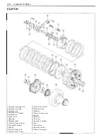
Page 104: ...CLUTCH Insta l l the washer spacer primary driven gear and washer Insta l l the clutch plates to the clutch sleeve hub and engage the cl utch pressure plate to the sleeve hub E N G I N E 3 68 ...

Page 105: ...Tightening torque Clutch sleeve hub holder 60 80 N m 6 0 8 0 kg m 43 5 58 0 lb ft I nstall the cl utch springs and clutch release plate Tighten the clutch spring bolts diagonal ly NOTE After tighteni ng the clutch spring bolts make sure to have no clearance between clutch plates I nstall the bearing and spacer to the crankshaft I nstall the primary drive gear ...

Page 106: ...ns counter clockwise freely and never turns clockwise I nsta l l the con caved washe r a n d t i ghten the shoe n ut to t h e specified to rq u e w i t h t h e specia l too l Con rad h o l d e r NOTE To prevent the con rad sma l l end from getting into the conrod holder insert the piston to the conrad small end i ng 90 1 1 0 N m 9 0 1 1 0 kg m 65 0 7 9 5 l b ft NOTE i nut has I Cl thread e I n sta...

Page 107: ...s and a new gasket I nstall the clutch cover CAUT ION Make sure to properly position the lip of the gasket Use a new gasket to prevent oil leakage Tighten the cl utch cover bolts NOTE Position the two clamps correctly F it a gasket to a bolt as shown in F ig CAUT I O N D o not use the o l d gasket to prevent oil leakage ...

Page 108: ...op or bottom when they are new When reassembl ing used parts install them in thei r original place and direction TOP RING AND 2ND RING Top ring and 2nd ring differ in the shape of ring face and the face of top ring is chrome plated whereas that of 2nd ring is not The color of 2nd ring appears darker than that of the top one Top and 2nd rings have the letter R marked on the top Be sure to bring the...

Page 109: ... the piston turn triangle mark CD on the piston head to exhaust side 99000 25 1 40 SUZ U K I Moly Paste Before mounting the cyl inder block oil the big end and sma l l end of the conrad and also the slid ing su rface of the piston F it dowel pins to cran kcase and then fit the gasket CAUT I ON To prevent oil leakage do not use the old gasket again always use a new one Hold each piston ring with th...

Page 110: ...head gasket to prevent oil leakage Do not use the old gasket Copper washers and cap nuts are also used to secure the cyl i nder head These parts must be fitted in the correct position as shown in the i l lustration Copper washer Stee l washer With the head snugly seated on the cyl inder secure it by tightening the nuts diagonal ly Tighten each nut to the torque value specified below Cylinder head ...

Page 111: ... i nto the camshaft Engage the chain on the cam sprocket with the locating pin ho le at just before top position NOT E D o not rotate magneto rotor while doing this When the sprocket is not positioned correctly turn the sprocket When install ing the cam shaft into the cam sprocket pay attention not to dislodge the locating pin or it may fall into the crankcase Al ign the marks on the camshaft so t...

Page 112: ...e rocker arms and shafts After inserting the shafts tighten the set bolts NOT E Use a conically recessed top bolt as the set bolts CAUT I ON Use a new 0 ring Q o n the rocker arm shafts to prevent oil leakage Use a new gasket on the set bolts to prevent oil leakage DE COMPRESSION SHAFT Apply SUZU K I M O LY PASTE to the de com pression shaft and then insert the de compres sion shaft E N G I N E 3 ...

Page 113: ... n d cam d rive cha i n e F i t t h e two d owe l p i n s CD to t h e cy l i n de r h ea d side F it the camshaft e n d cap F i t a gasket to each h ea d cover bo lt as shown i n F ig CAUT I ON Do not use the o l d gaskets to prevent oil leakage NOTE When tightening the cyl i nder head cover bolts piston position must be at top dead center on compression stroke Lightly tighte n the cy l i n d e r ...

Page 114: ...inder and tighten the two Al len bolts to the specified torque Tightening torque 8 1 2 N m 0 8 1 2 kg m 6 0 8 5 lb ft Fit an 0 ring and spring and tighten the bolt to the specified torque Tightening torque CAUT I ON 7 9 N m 0 7 0 9 kg m 5 0 6 5 l b ft Always use a new gasket and a 0 ring to prevent oil leakage VALVE CLEARANCE After tightening the head cover bolts check and adjust the valve clearan...

Page 115: ... j Spiral spring jJ Gasket D I SA S S E M B LY After removing the nut CD take out the recoil starter related parts from the housing CD Nut Spacer Friction plate j Ratchet Ratchet guide Pin Spring cover Reel Spring WAR N I NG When removing the reel spiral spring will expand Protect your hands with gloves Gasket position ...

Page 116: ...9000 25030 For U S model SUZUK I Super G rease A 99000 250 1 0 For other models Turn the starter rope on the reel properly After i nstal ling the spi ral spring engage the part of reel with the part of spiral spring Apply grease to the shaft and ratchet 99000 25030 For U S model 99000 250 1 0 For other models SUZ U K I Super G rease A Spiral spring tension adjustment Hook the rope onto the hook pa...

Page 117: ......

Page 118: ...FORMATION 4 1 2 REAR AXLE 4 1 3 REMOVAL AND DISASSEMBLY 4 1 3 REASSEMBLY 4 1 3 DIFFERENTIAL BEVEL GEARS CONSTRUCTION 4 1 4 REMOVAL 4 1 5 FRONT DRIVE BEVEL GEAR HOUSING 4 1 7 DISASSEMBLY 4 1 7 INSPECTION 4 1 8 REASSEMBLY 4 1 9 FRONT DRIVEN BEVEL GEAR AND DIFFERENTIAL BEVEL GEARS 4 2 1 DISASSEMBLY 4 2 1 INSPECTION AND SERVICING 4 25 BACKLASH MEASUREMENT 4 30 FRONT DRIVEN BEVEL GEAR TO DRIVEN BEVEL G...

Page 119: ...4 1 S H A FT D R I V E A N D D I F F E R E N T I A L D R IVE L I N E ...

Page 120: ...l lar Washer 0 ring Spacer Oil seal J R ight side bearing Rear final driven gear Rear final driven shaft Left side bearing jJ Shim Secondary d rive bevel gear Circlip j Secondary driven bevel gear Secondary d riven output shaft rear bearing Secondary driven output shaft Sh im Secondary d riven output shaft front bearing Oil seal Spacer 0 ring Washer Col lar Front d rive output yoke C ring Universa...

Page 121: ... Remove the engine Refer to page 3 4 Separate the crankcase Refer to page 3 26 Remove the secondary d riven output shaft Remove the sub transmissio n output shaft DISASSEMBLY SECONDARY D R I V E N O UTPUT SHAFT Remove the circl ip 09900 06 1 07 Snap ring pl iers ...

Page 122: ...the front drive output yoke and propel ler shaft joint yoke Remove the bearing from propel ler shaft joint yoke by the same manner of front drive output yoke NOT E Take care not to drop the needle roller Loosen the front drive output yoke nut by hold ing the yoke with vise S H A F T D R I V E A N D D I F F E R E N T I A L 4 4 ...

Page 123: ... the bearing and shims with the hydraulic press SUB TRANSMISSION OUTPUT SHAFT Loosen the sub transmission output shaft nut with the special tool and vise 0992 1 5 1 9 1 0 Output shaft holder 09924 5 1 9 1 0 Not available 27 mm deep socket in U S model ...

Page 124: ...ct the secondary driven output shaft for distortion The drive and driven bevel gears must be inspected thoroughly for excessive wear or damage It is important that both gears be in good condition to maintain proper tooth contact REASSEM B LY Reassemble the gears in the reverse order of disassembly and also carry out the following steps NOT E Before reassembly thoroughly clean all parts in cleaning...

Page 125: ...the secondary d riven output shaft Apply TH R EAD LOCK 1 303 to the thread of nut 99000 32030 For U S model Thread Lock Super 1 303 99000 32 1 20 For the other Thread Lock 1 324 models Tighten the front drive output yoke nut to the specified torque Tightening torque 90 1 1 0 N m 9 0 1 1 0 kg m 65 0 79 5 lb ft When insta l ling the universal joint take care not to drop the need le rol ler from cage...

Page 126: ...or the other Thread Lock 111 324 models Tighten the sub transm ission output shaft nut to the specified torque with the special tool Tightening torque 0992 1 5 1 9 1 0 09924 5191 0 Not available in U S model 90 1 1 0 N m 9 0 1 1 0 kg m 65 0 79 5 lb ft Output shaft holder 27 mm deep socket SECON DARY G EARS SH I M ADJUSTM ENT is necessary S H A FT D R I V E A N D D I F F E R E N T I A L 4 8 ...

Page 127: ...ndary bevel gear backlash NOTE 0 05 0 32 mm 0 002 0 01 3 in Remove the coupl i ng and coupl ing joints when measuring the backlash I f the backlash is not within the specification the shims must be changed and the backlash should be re checked u ntil correct Refer to the chart at right for appropriate changes NOTE When changing the sh ims measure the th ick ness of old sh ims Using the th ickness ...

Page 128: ...ssembly sub section and complete I f tooth contact is fou nd to be incorrect CD and the shims of the secondary drive bevel gear and secondary driven bevel gear must be chang ed tooth contact shou ld be re checked u ntil correct CAUTION After the tooth contact adjustment has been performed the backlash must be re checked because it may have changed Refer to the backlash check sub section and readju...

Page 129: ...te from the gear teeth and lubricate the teeth with engine oil Apply TH R EAD LOCK SUP E R 1 303 to the drive gear nut and front drive output yoke nut 99000 32030 For US model Thread Lock 1 303 99000 32 1 20 For the other Thread Lock 1 324 models Tighten the sub transm ission output shaft nut and front drive output yoke nut to the specified torque Refer to page 4 7 and 4 8 Tightening torque 90 1 1...

Page 130: ...y grease to the Iips seals Tightening torque 90 1 1 0 N m 9 0 1 1 0 kg m 65 0 79 5 lb ft Apply TH R EAD LOCK 1 303 Thickness mm 0 80 0 85 0 90 0 95 1 00 1 05 1 1 0 1 1 5 1 20 S H A F T D R I V E A N D D I F F E R E N T I A L 4 1 2 Tightening torque 90 1 1 0 N m 9 0 1 1 0 kg m 65 0 79 5 lb ft List of shim Part No Thickness mm 24935 19800 090 0 90 24935 1 9800 095 0 95 24935 1 9800 1 00 1 00 24935 1...

Page 131: ...arate the crankcase Refer to page 3 26 Remove the secondary driven output shaft and sub transmission output shaft Refer to page 4 2 Remove the rear final d riven shaft Remove the circl ip with the special tool 09900 06 1 07 Snap ring pliers REASSEMBLY I nstall the rear final driven gear onto the shaft as shown in the i l lustration ...

Page 132: ...asher 0 ring Spacer j Dust seal F ront d rive bevel gear rear bearing Spacer jj Front drive bevel gear front bearing Front d rive bevel gear F ront driven bevel gear housing right bearing D ifferential bevel gear case Shim Front d ifferential right side gear Pinion Front differential pinion shaft Front differential left side gear Wave washer Shim Front differential bevel gear hub Shim Front driven...

Page 133: ... and then l oosen the ax l e n u t after remov i n g t h e cotter p i n R emove the front whee l s R emove t h e u n iversa l j o i n t f r o m d i ffere nt i a l gear case w i t h the specia l too l 09924 2 1 9 1 0 Whee l h u b remover set R emove the ax l e shaft D i scon nect the se l ect i o n l ever cab l e a n d b reather h ose R emove the p rope l l er shaft cover Loosen the p rope l l er s...

Page 134: ...ns and then loosen the right and left tie rod end nuts Remove the right tie rod Loosen the front d ifferential securing nuts Remove the front differential from chassis S H A F T D R I V E A N D D I F F E R E N T I A L 4 1 6 ...

Page 135: ...I NG D I SASS E MB LY Loosen the nuts and remove the coupling Loosen the front drive bevel gear housing bolts Remove the drive gear housing Remove the drive gear 0 ring and shims NOTE Do not lose the removed shims Loosen the front drive bevel gear nut by holding the flange with vise ...

Page 136: ...uter race with the special tool 09941 549 1 1 Bearing outer race remover 099 1 3 8451 0 Bearing installer I NSPECTION I nspect and check the fol lowing items Bearing race wear and brinell ing Worn or damaged bearing Front drive bevel gear housing brinell ing Worn oil seal I f the excessive wear is fou nd replace the oil seal and col lar S H A F T D R I V E A N D D I F F E R E N T I A L 4 1 8 ...

Page 137: ...tall a new front drive bevel gear front bearing with the special tool 09941 749 1 0 Bearing instal ler I nstall a new spacer Apply TH R EAD LOCK SUP E R 1 303 to the thread of gear shaft 99000 32030 Thread Lock Super 1 303 For US model 99000 32 1 20 Thread Lock Super 1 324 For other models Tighten the front drive bevel gear nut to speci fied torque Tighten ing torque 1 1 0 1 30 N m 1 1 0 1 3 0 kg ...

Page 138: ...If the bearing pre load is not with in the specifica tion retighten the nut to the specified torque and bring the pre load to the specification Tightening torque CAUT I ON 90 1 1 0 N m 9 0 1 1 0 kg m 65 0 79 5 lb ft It is necessary to check the backlash and tooth contact when chang ing the gear bearing and or outer race R E F E R TO SH I M ADJUSTMENT SECT ION PROPE L LE R SHAFT I NSPECT ION I nspe...

Page 139: ... T I A L FRONT DRIVEN BEVEL GEAR A N D D I F F ERENTIAL GEARS D ISASS E MB LY Loosen the driven bevel gear bearing case securing bolts Remove the driven bevel gear bearing case Remove the cam stopper bolt and cam cover Remove the washer and spring ...

Page 140: ... Remove the cam shaft and shift fork shaft Remove the cam and washer Remove the sliding dog and shift fork Remove the driven gear and shims S H A F T D R I V E A N D D I F F E R E NT I A L 4 22 ...

Page 141: ... Remove the differential bevel gear case from the front driven bevel gear housing O i l seal bearing removal and reinstallation Remove the dust seal with the special tool 099 1 3 50 1 2 1 O i l seal remover Remove the front driven output shaft bearing with the special tool 099 1 3 75820 Bearing remover ...

Page 142: ...specia l tools 09924 7451 0 I nstal ler handle 09924 74520 I nstal ler N OT E When installing the bearing tap on the punched mark side of bearing with the bearing installer I nsta l l a new front d riven output shaft bearing with the specia l too l 0991 3 75520 Bearing instal ler NOT E When installing the bearing tap on the punched mark side of bearing with the bearing installer S H A FT D R I V E...

Page 143: ...I N G BEAR I NGS I nspect the play of bearing inner race by hand while it is in the case Rotate the inner race by hand to inspect for abnormal noise and smooth rotation Replace the bearing if there is anything unusual O I L SEAL I nspect the oil seal for wear I f the excessive wear is found replace the oil seal and col lar with new ones AXLE SHAFT NOT E D o not disassemble the axle shaft joint ...

Page 144: ... an excessive p lay is noted rep lace it with a new u n it as an assembly D I F F E R ENT I A L BEVE L G EA R CASE e Loosen the front d i fferentia l bevel gear h u b bolts w ith t h e special too l 09900 00401 H exagon wrench set CD Sh im Wave washer F ront d i fferential l eft side gear S H A F T D R I V E A N D D I F F E R E N T I A L 4 26 ...

Page 145: ...netic hand CD Thrust washer Pinion Front d ifferential pinion shaft Remove the front d ifferential right side gear and shims NOTE Do not lose the removed shims M EASU R I NG TH E BACK LASH I nstall the right side gear removed shims pinion shaft and pinions in the original position 0 ...

Page 146: ...ges F ront d ifferentia l right side gear back lash NOT E 0 05 0 1 m m 0 002 0 004 i n When changing the shims measure the th ick ness of the old shim Using the th ickness of the o ld shims as a gu ide adjust the backlash by referring to the chart at right S H A FT D R I V E A N D D I F F E R E N T I A L 4 28 Backlash Shim adjustment U nder 0 05 mm Decrease sh i m 0 002 i n thickness 0 05 0 1 mm C...

Page 147: ... must be changed Clearance N OTE 0 4 0 6 mm 0 0 1 6 0 024 in When changing the shims measure the th ick ness of the old shims as a guide adjust the c learance by referring the right chart e Apply TH R EAD LOCK SUPE R 1 303 to the differential bevel gear hub bolts 99000 32030 Thread Lock Super 1 303 For US model 99000 32 1 1 0 For the other Thread Lock Super 1 322 models Tighten the front different...

Page 148: ... front driven bevel gear on the differ ential bevel gear hub I nstal l the removed shim on the drive bevel gear housing I nsta l l the drive bevel gear into the front driven bevel gear housing BACKLASH MEAS U REMENT Set up a dial gauge as shown in the F ig D ifferential drive gear backlash 0 0 05 mm 0 0 002 in S H A F T D R I V E A N D D I F F E R E N T I A L 4 30 ...

Page 149: ...u b I f backlash is too sma l l a I nsta l l a th icker sh i m pack between final d riven bevel gear and the d ifferential bevel gear hub FRONT DRIVEN BEVEL GEAR TO DRIVEN BEVEL GEAR BEARING SHIM ADJUSTMENT M easu re the clearance between the d riven gear and beari ng i n the fo l lowing steps Measure the height CD of the bearing i nner race surface and bearing case flange with the special tools a...

Page 150: ... V block set in US model Decide the proper shim thickness b y the following formu la CD 0 1 5 mm Shim thickness 0 1 5 mm Proper clearance Proper shim thickness EXAMP LE 5 00 mm CD 3 75 mm 5 00 3 75 0 1 5 1 1 0 So 1 1 0 is the proper shim size Select the 1 1 0 mm shims from the right table SHAFT D R I V E A N D D I F F E R E N T I A L 4 32 J List of shims Refer to page 4 38 U n it mm Part No Shim t...

Page 151: ...el gear several turns in each direction whi le loading the driven bevel gear This wil l provide a contact pattern on the coated teeth of the drive bevel gear Remove the d rive bevel gear and inspect the coated teeth of the drive bevel gear The con tact patch shou ld be as shown at right If the tooth contact pattern is correct as shown in go to the Final Assembly sub section If the tooth contact pa...

Page 152: ...the driven gear bearing case remove the driven gear bearing case front driven bevel gear and front bevel gear housing from front driven bevel gear housing Clean off any machinist s dye or paste from the gear teeth and lubricate the teeth with Hypoid gear oil I nstal l new 0 rings to the driven gear bearing case and front drive bevel gear housing Coat the 0 rings with grease I nsta l l the front dr...

Page 153: ...g m 1 4 5 1 9 0 lb ft AI ign the punched mark CD of cam shaft with punched mark of cam I nsta II the dog and shift fork into the driven gear bearing case I nstal l the shift fork shaft and shift cam into the driven gear bearing case as shown in the i l lustration CD Washer Shift fork shaft Spring J Driven bevel gear Washer bearing case Cam shaft Dog Cam Shift fork ...

Page 154: ...2 0 2 6 kg m 1 4 5 1 9 0 l b ft Remou nt the front d ifferentia l Tighten the mou nti ng nuts to the specified torqu e Tighte n i ng torque 40 50 N m 4 0 5 0 kg m 29 0 36 0 l b ft When insta l l i ng the selection lever d ifferential gear case side to the cam shaft a l ign the sl it CD of lever with mark of cam shaft as shown i n the i l l u stration S H A F T D R I V E A N D D I F F E R E N T I A...

Page 155: ...ling joint nuts to the specified torque after applying TH R EAD LOCK SUPE R 1 303 to the thread 40 50 N m Tighten ing torque 4 0 5 0 kg m J 29 0 36 0 lb ft 99000 32030 Thread Lock Super 1 303 For U S model 99000 321 1 0 For the other Thread Lock Super 1 322 models Engage the universal joint to the differential spline securely Tighten the axle nut and wheel set nut Tightening torque 85 1 1 5 N m Ax...

Page 156: ...7327 34220 0 50 mm 2 7327 34230 0 60 m m Tighte n i ng torq ue 1 1 0 1 30 N m 1 1 0 1 3 0 kg m 79 5 94 0 l b ft Apply grease to 0 r i ng Tighte n i ng torq u e 20 30 N m 2 0 3 0 kg m 1 4 5 2 1 5 l b ft Apply grease to 0 r i n g A p p l y th read l o c k 1 303 Tighte n i ng torque 23 30 N m Apply g rease to t h e l i p a n d o u t s i d e of the o i I sea l L i st o f s h i m s S h i m Pa rt No t h...

Page 157: ...A N D D I F F E R E N T I A L Tightening torque 40 50 N m 4 0 5 0 kg m 29 0 36 0 lb ft Tightening torque 40 50 N m 4 0 5 0 kg m 29 0 36 0 lb ft Apply TH R EAD LOCK 1 303 for U S model Apply TH R EAD LOCK 1 322 for other models ...

Page 158: ...PECIFIC TION 5 7 I D NO LOC TION 5 7 SLOW SYSTEM 5 8 M IN SYSTEM 5 9 ST ARTER SYSTEM WITfi UMITER S 1 0 FLO T SYSTEM 5 1 1 C RBURETOR REMOVAL ND DIS SSEMBLY 5 1 2 INSPECTION 5 1 4 NEEDLE VALVE INSPECTION 5 1 4 FLOAT HEIGfiT DJUSTMENT 5 1 4 CARBURETOR REASSEMBLY AND REMOUNTING 5 1 5 FUEL T NK REMOVAL ND REMOUNTI G 5 1 5 FUEL LINE INSPECTION 5 1 5 REMOV L 5 1 5 REMOUNTING 5 1 6 LUBRICATION SYSTEM 5 ...

Page 159: ...rom the fuel tan k to the carburetor The pump is necessary as the fuel tan k is mounted lower than the carburetor fuel bowl In addition the pump assures an adequate supply of fuel to the engine under the steepest cl imbing conditions as wel l as while running across rough terrain Carburetor Fuel tank Fuel hose No 1 ...

Page 160: ...S M F U E L A N D L U B R I CAT I O N SYST E M 5 2 A valve is provided at the top of the fuel cock lever and can switch over to OF F ON and R ES With the valve ON normal the main passage opens With the valve OF F both holes close OF F ...

Page 161: ...the two screws and then remove the fuel cock assembly CD Screw Fuel cock body ON fuel strainer R ES fuel strainer F U E L ST RAI N E R Wash the strainer with non flammable cleaning solvent and blow compressed air through it to dry off solvent N OTE When reinstal l ing the fuel cock to the fuel tank fit a new 0 ring correctly A lways use a new 0 ring to prevent fuel leakage ...

Page 162: ...rom the tan k into the diaphragm s chamber As positive pressure is applied the spring forces the diaphragm back pushing the fuel through the outlet to the carburetor A series of check valves is used in the fuel flow route to allow the fuel to move in only one direction through the pump body The pump is mounted as near to the fuel tank as possible for the greatest effi ciency Fuel from fuel cock Ne...

Page 163: ...um hose CD Slide the clips and disconnect the fuel in let hose and fuel outlet hose Remove the two bolts and then remove the fuel pump In case of fuel leak at fuel pump or air leak into the fuel l i ne check the fol lowing items Broken diaphragm Malfunction of check valve Loose screws on fuel pump If any defect is found replace the fuel pump assembly with a new one ...

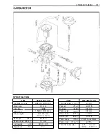
Page 164: ...nger spring Starter plunger Starter l imiter Jet needle stopper plate E ring Jet needle j Throttle valve Throttle valve return spring Breather hose Throttle stop screw j Pilot screw Pilot jet Needle valve j Float arm pin Needle jet Air bleeder Main jet Float Gasket Drain screw Drain hose One way valve ...

Page 165: ...ve seat V S Starter jet G S Pilot screw P S Pilot air jet P A J Throttle cable play I D NO LOCATION Each carburetor has I D Number CD printed on the carburetor body accord ing to its specifications SPEC I F ICAT I O N M I KU N I VM24SS 24 mm 0 94 in 1 9BOO 1 400 50 r min 24 5 1 0 mm 0 96 0 04 in 1 00 1 0 mm 0 04 in 5 L2 1 3rd 0 1 1 5 22 5 0 8 mm 0 03 1 in 0 7 mm 0 028 in 1 2 mm 0 05 in 30 P R E SE...

Page 166: ...by the pilot jet is mixed with the proper amount of air metered by the pilot air jet and is separated into fine particles Mixture then exits into the main bore through the pilot outlet The pi l ot screw controls the amount of mixture When the piston valve opens a l ittle the mixture jets through the by pass and the pilot outlet Pilot jet Pilot air jet Fuel Air mixture Fuel ...

Page 167: ...the piston valve is 1 4 Full open The fuel passes through the main jet and mixes with air metered by the main air jet The mixture passes by the clearance between the needle jet and jet needle and then exits into the main bore after being metered by the jet need le Main jet Main air jet J Air F uel Air mixture F uel ...

Page 168: ...e starter system features both a summer and winter starter setting for easy starting in a l l air temperature conditions The starter circuit is fitted with a limiter device that allows the starter plunger to only move to the summer starting position under normal use of the starter Summer starting temperature conditions are considered to be in the 5 C 40o F and higher range Under winter type air te...

Page 169: ... in float chamber floats are up and need le valve remains pushed up against valve seat Under this condition no fuel enters the float chamber As the fuel level fal ls floats go down and needle valve unseats itself to admit fuel into the chamber In this manner needle valve admits and shuts off fuel alternately to maintain a practical ly constant fuel level inside the float chamber J l j L I _ J L __...

Page 170: ...en the nut and separate the starter plunger assembly Loosen two carburetor clamp screws and then remove the carburetor Remove the float chamber body by removing four screws with the special tool 09900 09003 I mpact driver set Pul l out the float arm pin and remove the float CAUTION When removing the float arm p i n b e careful not to damage the carburetor body F U E L A N D L U B R I C AT I O N S ...

Page 171: ... pilot jet Remove the plate by removing the screw then remove the needle valve seat Remove the nut 0 and take out the l i miter Separate the throttle valve assembly Top cap Retu rn spring Throttle valve j Stopper plate E ring Jet needle j Needle jet Main jet Pilot jet Needle valve Limiter ...

Page 172: ...loat chamber Clean the float chamber and float parts with gasoline If the needle is worn as shown in the i l lustration replace it together with a valve seat Clean the fuel passage of the mixing chamber with compressed air FlOAT HEIGHT ADJUSTMENT To check the float height invert the carburetor body with the float arm kept free measure the height while float arm is just in contact with needle valve...

Page 173: ...ustment Refer to page 2 8 F U El TAN K R E MOVA L A N D R E MO U NTI N G FUEL L I NE I NS P ECTION Visually inspect the fuel lines fuel tan k and tank cap for damage and fuel leakage If they are found to be damaged replace them with new ones REMOVAL Remove the front carrier and fender Refer to page 7 1 Remove the engine Refer to page 3 4 Turn the fuel cock to 0 F F position Sl ide the clip CD and ...

Page 174: ...lide down and back the fuel tank and remove it from the frame REMOUNTING Remount the fuel tank by reversing the sequence of removal and following step is necessary When mounting the fuel tan k bolts right side rear bolt is installed with the ignition coil mou nting bracket F U E L A N D L U B R I CAT I O N SYST E M 5 1 6 ...

Page 175: ...05 NOTE Engine tachometer Not available in U S model E ngine oil must be warmed up to 60 C 1 40 F when checking the oil pressure 0991 5 7451 0 Oi l pressu re gauge 0991 5 74530 Adaptor O i l pressure specification Above 30 kPa 0 30 kg cm2 4 3 psi Below 70 kPa 0 70 kg cm2 1 0 0 psi at 3 000 r min Oil temp at 60 C 1 40 F If the oil pressure is lower or higher than the specifications several causes m...

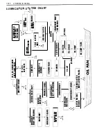
Page 176: ...E WAY CLUTCH BEARING FIRST CLUTCH SHOE 4 H CON ROD SMAll END CONROD BIG END BEARING L__ _ C _ Y_ UN _ D _ ER _ ___J I J CL _ U _ TC H _ C _ O V _ ER ____j l CRANKSHAFT RIGHT I END BEARING OIL L t BY PASS OIL JET 1 J CLUTCH RElEASE BEARING SECOND CLUTCH Oil PUMP I DRIVE DRIVEN PlATES 6 0 1 I L PAN J I c w 0 0 0 2 en m 4 s 0 t 0 c m z 0 c OJ 0 n I 0 z I m s ...

Page 177: ...5 1 9 F U E L A N D L U B R I CAT I O N SYST E M LUBRICATION SYSTEM ...

Page 178: ...ER MOTOR REMOVAL AND DISASSEMBLY 6 6 ST ARTER MOTOR INSPECTION 6 7 ST ARTER MOTOR REASSEMBLY 6 8 ST ARTER RELAY INSPECTION 6 1 0 NEUTRAL RELAY INSPECTION 6 1 0 LAMPS 6 1 1 INSPECTION 6 1 1 SWITCHES 6 1 2 INSPECTION 6 12 BATTERY 6 1 4 SPECI ICATIONS 6 1 4 INITIAL CHARGING 6 1 4 SERVICING 6 1 4 RECHARGING OPERATION 6 1 5 SERVICE LI E 6 1 6 ...

Page 179: ...t flows through the primary side of the ignition coil A high voltage current is induced in the secondary windings of the ignition coil resu lting in strong spark between the spark plug gap R otor W I R E COLOR B Black G Green B l Blue y Yellow MAG N ETO B R B W B Y W BI Pick up coil AC generator power source coils Spark plug Black with Red tracer Black with White tracer Black with Yel low tracer W...

Page 180: ...ro tester B Y G W 90 1 40 n B B I Y 1 05 1 60 n Remove the ignition coil from the fra me Test the ignition coil for sparking performance Test connection is as indicated Make sure that the three needle sparking d istance is at least 8 mm 09900 28 1 06 Electro tester 8 mm 0 3 in STD Spark performance Checking with pocket tester 09900 25002 Pocket tester Ignition coil resistance Primary E8 tap 8 tap ...

Page 181: ... 0 e c CD I f the resistance checked is incorrect replace the CDI unit 09900 25002 Pocket tester Unit Approx kn ffi Probe of tester to 8 8 1 G 8 R W 8 1 8 W 8 Y 8 I 1 0 80 1 0 60 1 0 60 00 1 0 60 2 1 0 8 1 5 40 5 30 4 20 00 4 20 20 1 00 G 3 20 3 20 1 6 00 1 6 8 40 8 R 2 1 0 2 1 0 1 6 00 0 5 30 W 81 00 00 00 00 00 00 8 W 2 1 0 2 1 0 1 6 0 00 5 30 8 Y 00 00 00 00 00 00 WI R E CO LO R B Bl G 00 Black...

Page 182: ...e bat tery is fully charged condition STD charging output 09900 25002 1 4 0 1 5 5V DC at 5 000 r min Pocket tester AC G E N E RATOR NO LOAD PE R FO R MANCE Remove the seat Discon nect the AC generator lead wire coupler Start the engine and keep it running at 5 000 r min Using the pocket tester measure the AC voltage between the three yellow lead wires If the tester reads u nder 55V the AC generato...

Page 183: ...t cover battery and front fender R efer to page 7 2 Using the pocket tester X 1 kS1 range measure the resistance between the lead wires in the fol lowing table If the resistance checked is incorrect replace the regulator rectifier 09900 25002 Pocket tester Unit Approx kn EB Probe of tester to K R 0 B B W v v v R 00 00 00 00 00 0 0 B 6 20 0 1 1 2 7 2 7 2 7 Q Q K B W 6 20 0 1 1 1 6 1 6 1 6 0 Q 0 v K...

Page 184: ... amperes to start the engine I I Battery I I I _I_ STARTER M OTOR REMOVAL AND DISASSEMBLY Disconnect the starter motor lead wire by removing the nut then remove the starter motor by removing the mounting bolts Engine ground wire Disassemble the starter motor as shown in the fol lowi ng i l lustration Neutral switch Y B WI R E CO LOR Bl B lue 0 Orange R Red B W B lack with White tracer BI B Blue w ...

Page 185: ...r with 400 or similar fine emery paper when it is dirty After pol ishing it wipe the commutator with a clean dry cloth Measure the commutator under cut CD Service Lim it 0 2 mm 0 008 in ARMAT U R E COI L Using a pocket tester check the coil for open and ground by placing probe pins on each commutator segment and rotor core to test for ground and on any two segments at various places to test for op...

Page 186: ...Y 0 R I NG CAUT I ON R eplace the 0 rings with new ones to prevent oil leakage and moisture B R US H HOLD E R Align the groove CD on the housing end with the tab of brush holder A R MAT U R E Apply a smal l quantity of moly paste to the armature end 99000 25 1 40 SUZU K I Moly Paste E L E CT R I CA L SYSTE M 6 8 ...

Page 187: ...housing end with the tabs of washer 99000 25030 For U S model 99000 2501 0 For other models HOUSI NG E N D SUZU K I Super G rease I I A SUZ U K I Super G rease A Al ign the engraved l ine marks on the housing ends with the engraved l ine marks on the starter motor case HOUSING SCR EW Apply a sma l l quantity of TH R EAD LOCK 1 342 to the starter motor housing screws and tighten them 99000 32050 Th...

Page 188: ... relay is in sound condition conti nuity is found 09900 25002 Pocket tester Disconnect the two lead wi res from the starter relay Check the coil for open ground and ohmic resistance The coil is in good condition if the resistance is as follows 09900 25002 Pocket tester STD resistance 3 1 st J NEUTRAl RElAY INSPECTION Remove the neutral relay from the starter relay holder e Apply 12 volts to CD and...

Page 189: ...ontinu ity I f the bulb does not l ight i nspect the wiring for open or short circuit Headlight 1 2V 30 30W Taillight 1 2V 5W Speedometer 1 2V 3 4W Reverse indicator l ight 1 2V 3 4W Neutral indicator l ight 1 2V 3 4W 09900 25002 Pocket tester CAUTI ON Do not overtighten the lens fitting screws ...

Page 190: ...ce the respective switch assemblies with new ones 09900 25002 Pocket tester ENG I N E STOP AND START SWITCH COLO R B W B Y 0 0 W Y G POS I T I ON OFF o RUN o STA RT Push o iO D I M MER SWITCH N G r y w H I LO 0 o IGNITI ON AND LIGHTI NG SWITCH COLO R R 0 G r B Y B W POS I T I O N O F F 0 o ON o o L I G HT o o E L E CT R I CA L SYST E M 6 1 2 ...

Page 191: ... B B I R B l N E UT R A L R EV E RS E WI R E CO LO R 0 O ra nge B W Black with White tracer Gr G ray 0 W Orange with White tracer W Wh ite Y G Yel low with G reen tracer Y Yel l ow B Y B l ack with Yel l ow tracer B l B l ue B I R B l ue with Red tracer R R ed B I B B l ue with B l ack tracer ...

Page 192: ...arging time 1 4A The charging time for a new battery is determined by the number of months that have elapsed since the date of manufacture Confirmation for date of manufacture Date of manufacture is indicated by a three part number CD as shown in the photograph each indicating month date and year Near the end of charging period adjust the specific gravity of electrolyte to val ue specified After c...

Page 193: ... as shown in figure Check the reading as corrected to 20 C with chart to determine the recharging time in hour by constant current charging at a charging rate of 1 4 amperes which is tenth of the capacity of the present battery B e careful not to permit the electrolyte tempera ture to exceed 45 C 1 1 3 F at any time during the recharging operation I nterrupt the operation as necessary to let the e...

Page 194: ...eriorate the per formance sulfation Replace the battery with new one in such a case E L E CT R I CAL SYST E M 6 1 6 When a battery is left for a long term without using it is apt to subject to sulfation When the vehicle is not used for more than 1 month es pecially during the winter season recharge the battery once a month at least WAR N I N G Before charging a battery remove the seal cap from eac...

Page 195: ......

Page 196: ...AKE 7 7 FRONT U PEN ION 7 1 7 TEERING 7 25 FRONT fiEEL FRONT U PEN ION AND TEERING REA E BLING INFOR ATION 7 5 REAR BRAKE 7 37 REAR U PEN ION 7 2 REAR AXLE fiAFT 7 7 REAR BRAKE REAR U PEN ION AND REAR AXLE fiAFT REA E BL ING INFOR ATION 7 50 LEVER CA E 7 52 PU fi PULL CABLE 7 56 BRAKE fiO E ROUTING 7 59 ...

Page 197: ...l l C H ASS I S F RONT CAR R I E R A N D F RON T F E N D E R ...

Page 198: ...e Remove the band and remove the battery Disconnect the other lead wires Remove the seat and lever knobs by unscrewing the securing screws NOT E When installing the lever knobs apply T H R EAD LOCK SUPE R 1 303 1 322 to the securing screws 99000 32030 Thread Lock Super 1 303 For US model 99000 321 1 0 Thread Lock Super 1 322 For other models C H ASS I S 7 2 w D 1 ...

Page 199: ...7 3 C H ASS IS Remove the fuel tank cap and center cover After removing the center cover reinstall the fuel tank cap Loosen the front fender securing bolts and screws and then remove the front fender ...

Page 200: ...t the vehicle by jack or block Remove the wheel by removing the wheel set nuts REMOUNTING Tighten the wheel set nuts to the specified torq ue Tighten ing torque 45 65 N m 4 5 6 5 kg m 32 5 47 0 lb ft Tighteni ng torque C H ASS I S 7 4 I 45 65 N m 4 5 6 5 kg m 32 5 47 0 lb ft ...

Page 201: ...he wheel CAUT I ON When using the tire levers d o not scratch or h it the sealing portion hump of the wheel or it may cause air leakage R EASS E M BLY Lubricate the tire beads a nd rim flanges with clean water CAUT I O N Never use engine o i l o r gasol ine because they w i l l deteriorate the tire CAUT I O N The standard tire fitted on the vehicle i s 2 2 x 8 00 1 0 for front and 25 x 1 2 00 1 0 ...

Page 202: ...page 2 1 1 WAR N I NG D o not inflate the tire to more than 70 kPa 0 7 kg cm2 1 0 psi Over inflation may damage the tire We strongly recommend that a manual type air pump be used rather than a h igh pressure tire filler as fou nd in gas stations N OT E Check the rim l i ne cast o n the tire side wal l s It must be equally spaced from the wheel rim ali the way around If the d istance between the ri...

Page 203: ...ot t Piston and cup se Master cylinder Clamp j Gasket Air bleeder valve Dust seal Piston jJ Cup Spring Wheel cylinder Q l Pin Brake panel Brake shoe Stopper Strut No 1 Shoe holder sprmg No 2 S oe h holder sprIng Dust seal Brake drum Tightening to rq u e r kg L 1 N m 5 8 ...

Page 204: ... Loosen the axle nut by applying the front brake Remove the brake drum NOT E If removal of brake d rum i s d ifficult push the shoe hold spring by using the screw driver Driver Remove the front wheel hub with the special tool 09924 21 9 1 0 Wheel hub remover 09930 301 02 Sl iding shaft C H ASS I S 7 8 ...

Page 205: ... C H ASS IS Remove the two shoe holder springs by turn ing the pins CD 90 and then remove the shoes Discon nect the brake pipe with pipe wrench Loosen the brake panel bolts and then remove the brake panel ...

Page 206: ...tons and spring INSPECTION B R A K E D R U M CD Gasket Dust seal Piston Spring Wheel cylinder Measure the brake drum I D to determine the extent of wear and if the limit is exceeded by the wear noted replace the brake drum The value of this limit is indicated inside of drum Service Limit 1 65 7 mm 6 52 in C H ASS I S 7 1 0 ...

Page 207: ... I nspect the cup and boot for scratches or other damage Replace the cup and boot with new ones if any defects are found REASSEMBLY AND REMOUNTING Reassemble and remount the front brake in the reverse order of disassembly and removal and also carry out the following steps CAUT I O N Wash the cylinder components with fresh brake flu id before reassembly Never use cleani ng solvent or gasoline to wa...

Page 208: ...SUZU K I Si licone Grease CAU T I ON B e careful not to apply too much grease to the part and If grease gets on the lining brake slippage w i l l result Tighten the brake panel bolts to the specified torque Tightening torque 1 8 28 N m 1 8 2 8 kg m 1 3 0 20 0 lb ft Tighten the brake pipe nut to the specified torque Tightening torque CAU T ION 1 3 18 N m 1 3 1 8 kg m 9 5 1 3 0 lb ft Bleed the air a...

Page 209: ... S I nstall the shoes CD strut and springs to the proper position as shown in figure WAR N I NG After completing the above steps make sure that the stopper CD is h itched on the holder spring Shoe holder spring N o 2 ...

Page 210: ...Strut Ratchet Screwdriver Apply grease to the inner spline of hub 99000 25030 For U S model 99000 2501 0 SUZU K I Super G rease A For other models Tighten the front wheel set nuts and axle nut to the specified torque Tighteni ng torque I tem N m kg m lb ft F ront W heel 45 65 4 5 6 5 32 5 41 0 set nut Axle nut 85 1 1 5 8 5 1 1 5 6 1 5 83 0 C H ASS I S 7 1 4 ...

Page 211: ...ke flu id adhering to any part of vehicle The fluid reacts chem ically with paint plastics rubber mate rials etc Remove the two clamp bolts and then remove the master cylinder assembly Remove the front brake lever Remove the reservoir cap and diaphragm Drain brake fluid Pu I I out the dust boot Remove the circlip with the special tool Remove the piston primary cup and spring 09900 061 08 CD Circl ...

Page 212: ... owing steps CAUT ION Wash the master cyl inder components with fresh brake fluid before reassembly N ever use cleaning solvent or gaso l ine to wash them Apply brake fluid to the cyl i nder bore and a l l the i nternals t o b e i nserted i nto the bore When remounting the master cyl inder on the hand lebars first tighten the u pper clamp bolt as shown M aste r cyl inder clamp bolt tighte n i ng t...

Page 213: ...ng torque Item N m kg m 40 60 4 0 6 0 50 70 5 0 7 0 1 20 1 70 1 2 0 1 7 0 44 66 4 4 6 6 lb ft 29 0 43 5 36 0 50 5 87 0 1 23 0 32 0 47 5 CD Shock absorber Steering knuckle end upper Steering knuckle end lower Wishbone arm upper Wishbone arm lower Bush ...

Page 214: ... 8 Loosen the brake hose retainer bolt CD Remove the brake hose stopper ring and then remove the brake hose Remove the cotter pin and loosen the steering knuckle arm pinch bolt Loosen the shock absorber upper mounting bolt and Upper Lower wishbone arm pivot bolts C H ASS I S 7 1 8 ...

Page 215: ...7 1 9 C H ASS I S Loosen the shock absorber lower bolt CD Loosen the knuckle upper lower bolts Loosen the steering knuckle end bolt by holding its end side with vise ...

Page 216: ... special tool 0991 3 50 1 2 1 1 Oil seal remover First tap the bearing with the bar to get the clearance between bearing and spacer Then remove the bearing with the special tool 09923 745 1 0 Bearing pu l ler 09930 301 02 Sliding shaft C HASS I S 7 20 ...

Page 217: ...for distortion or other damage BUSH I nspect the rubber bush shock absorber wishbone arm for wear or other damage If any damage or wear is noted replace it with a new one When replacing the wishbone arm bush apply TH R EAD LOCK SUPE R 1 303 to the outer surface of bush 99000 32030 Thread Lock Super 1 303 For U S model 99000 32 1 1 0 Thread Lock Super 1 322 For other models ...

Page 218: ... SEAL I nspect the dust seal lip for wear or damage If any wear or damage is noted replace it with a new one REASSEMBLY Reassemble and remount the front suspension in the reverse order of disassembly and removal and also carry out the fol lowing steps H U B B EARI NG Apply grease to the bearing and the dust seal before installing them 99000 25030 For U S model 99000 2501 0 SUZ U K I Super G rease ...

Page 219: ... l the out side bearing first NOTE When install ing the bearing sealed side of bearing comes outside CD Outer bearing I nner bearing Spacer Apply TH R EAD LOCK SUP E R 1 303 to the steering knuckle end bolt 99000 32030 Thread Lock Super 1 303 For U S model 99000 32 1 1 0 Thread Lock Super 1 322 For other models ...

Page 220: ...er 1 303 99000 32 1 1 0 Thread Lock Super 1 322 I For other models 44 66 N m I Tighten ing torque 4 4 6 6 kg m I _ 32 e Tighten the shock a bsorber u pper and l ower mou nting n uts and wishbone arm pivot nuts T ightening torque S hock absorber mou nting bolt Wishbone arm p ivot bolt 40 60 N m 4 0 6 0 kg m 29 0 43 5 l b ft 50 70 N m 5 0 7 0 kg m 36 0 50 5 l b ft Tighten the steering knuckle arm bo...

Page 221: ...r Tie rod end outer Tie rod end inner Dust seal Dust seal Dust seal Tightening torque Item N m 1 8 28 1 8 28 44 66 40 60 22 35 38 60 kg m lb ft 1 8 2 8 1 3 0 20 0 1 8 2 8 1 3 0 20 0 4 4 6 6 32 0 47 5 4 0 6 0 29 0 43 5 2 2 3 5 1 6 0 25 5 3 8 6 0 27 5 43 5 ...

Page 222: ... Remove the speedometer lower cover Disconnect the lead wires and speedometer cable Remove the speedometer Remove the front wheel Refer to page 7 4 Loosen the brake hose joint securing bolt Remove the selection lever cable securing clip C H ASS I S 7 26 ...

Page 223: ... S Loosen t h e hand lebars c l a m p bolts R emove the lever case Refer to page 7 52 Loosen the fue l tan k securing bolts Refer to page 5 1 5 After removing t h e cotter p i n l oosen the steering knuckle arm bolts ...

Page 224: ... end nuts Remove the tie rods right and left while pulling the fuel tank backward After removing the cotter pin loosen the steering shaft lower nut Remove the cotter pin Loosen the steering shaft holder bolts Remove the steering shaft C H ASS I S 7 28 ...

Page 225: ...nuts surface finishing of yellow are left hand thread INSPECTION I nspect the removed parts for the fol lowing ab normal ities Handlebars distortion Handlebars clamp wear D UST SEAL I nspect the dust seals and 0 rings for wear or damage T I E ROD I nspect the tie rod for distortion and the boot for wear I nspect the tie rod end for smooth movement c o O o o r __ ...

Page 226: ...LD E R I nspect the steering shaft for distortion o r bend I nspect the two steering shaft holders for wear REAS SEMBLY AND REMOUNTI NG Reassemble and remount the removed part i n the reverse order of disassembly and removal and also carry out the following steps C H ASS I S 7 30 ...

Page 227: ...aft 99000 25030 For U S model 99000 2501 0 For other models SUZ U K I Super G rease 1 1 A Fit the ring to the dust seal STE E R I NG SHAFT Apply grease to the steering shaft lower portion 99000 25030 For U S model 99000 250 1 0 For other models SUZ U K I Super G rease All Install a new 0 ring and dust cover 0 ...

Page 228: ...le arm bolt to the specified torque and insta l l new cotter pins Tightening torque Item N m kg m lb ft Q 38 60 3 8 6 0 27 5 43 5 22 35 2 2 3 5 1 6 0 25 5 40 60 4 0 6 0 29 0 43 5 Apply grease to the steering shaft holders and dust seals 99000 25030 For U S model 99000 250 1 0 For other models NOT E SUZU K I Super G rease I I All The dust seal end should be mounted on the steering shaft facing forw...

Page 229: ...ch a way that the cleanrances ahead of and behind the handlebar shou ld be equalized Tightening torque 1 8 28 N m 1 8 2 8 kg m 1 3 0 20 0 lb ft Route the brake hose properly Refer to page 7 57 TIE ROD When install ing the tie rod make sure that the narrow side of the tie rod comes inside NOTE Outside lock nuts surface finish ing of yel low are left hand thread ...

Page 230: ...e in Toe in 1 1 19 mm 0 43 0 75 in Temporarily tighten the fou r lock nuts Check that the distances C and D in i l lustration are equal If the distances C and D are not equal readjust the tie rod right or left whichever makes the toe in value closer to the specification Check the toe in again by measuring the dis tances A and B If the toe in is not within the specification repeat the adjustment as...

Page 231: ...7 35 C H ASS I S F RONT WH EEL F RONT S U S P E N S I ON AN D STEE R I N G R EAS SE M B L I NG I N FO R M AT I O N Ac B e f 1 _ _ _ L I VIEW A VIEW 8 ...

Page 232: ...ck absorber 40 60 4 0 6 0 29 0 43 5 mou nting bolt Steering knuckle arm 40 60 4 0 6 0 29 0 43 5 end pinch bolt Steering knuckle arm 40 60 4 0 6 0 29 0 43 5 pinch bolt Steering 7 shaft holder and dust seal Tie rod end 22 35 2 2 3 5 1 6 0 25 5 nut C H ASS I S 7 36 NOTE For U S model For other m odels SUZU K I Super G rease A SUZU K I Super G rease fo 99000 25030 99000 2501 0 Thread Lock Super Thread...

Page 233: ...L A N D D I S A S S E M B LY Remove the rear wheel Refer to page 7 4 Loosen the rear axle nut by applying the rear brake after removing the cotter pin Remove the brake durm Remove the 0 ring CD B rake drum 0 ring Rear wheel hub B rake shoe B rake cam shaft 0 ring j Breather hose 0 ring B rake cam lever Water drain hose j Plug ...

Page 234: ...pecial tools 09924 2 1 9 1 0 Wheel hub remover 09930 301 02 Sl iding shaft Remove the brake shoes Disconnect the rear brake cable water drain hose and breather hose Remove the brake panel by unscrewing the secu ring bolts C H ASS I S 7 38 ...

Page 235: ... bolt I N S P ECTI O N I nspect the dust seal and 0 ring for wear or other damage If wear or other damage is noted replace them with new ones I nspect the seal ring mounted on brake drum for any scuffing or flaws CAUT I O N The removed dust seal and 0 ring should be replaced with new ones ...

Page 236: ...0 25030 For U S model 99000 2501 0 SUZU K I Super G rease A For other models Insta l l the new 0 rings on brake camshaft When insta l l ing the brake cam lever on the camshaft al ign the punched mark CD of cam lever with sl it of camshaft Apply SUZU K I Bond No 1 2 1 6 to the mating surface of brake panel 99 1 04 3 1 1 60 For U S medels SUZU K I BON D No 1 21 6 99000 3 1 1 60 For other models Inst...

Page 237: ...G rease A For other models Apply SUZU K I BON D No 1 21 6 to the joint of bolts and hub and then insta l l a new 0 ring 99 104 31 1 60 For U S model SUZU K I Bond No 1 2 1 6 99000 31 1 60 For other models Tighten the rear axle nut to the specified torque Tightening torque 85 1 1 5 N m 8 5 1 1 5 kg m 61 5 83 0 lb ft After i nstalling the rear brake adjust the fol lowing items Rear brake cable play ...

Page 238: ...ening torque I I tem N m I 40 60 I 50 70 I kg m 4 0 6 0 5 0 7 0 I lb ft 29 0 43 5 36 0 50 5 C H ASS I S 7 42 CD Shock absorber D ust seal Outer bearmg Spacer I nner beanng Dust seal 0 Bush R ight suspension arm Left suspension arm ...

Page 239: ...CD and suspension arm mounting bolts and remove the suspension arm and shock absorber Remove the shock absorber lower bolt and nut and then separate the shock absorber from the suspension arm Remove the dust seal with the special tool 0991 3 501 2 1 O i l seal remover First tap the bearing with the bar to get the clearance between bearing and spacer uz z J I ...

Page 240: ...oiI leakage or other damage SUSPENSION A R M I nspect the suspension arm for distortion or other damage BUSH If wear or damage is noted replace the respective bushes When replacing the suspension arm bush apply TH R EAD LOCK SUP E R 1 3338 to outer surface of bush 99000 32020 Thread Lock Super 1 3338 For U S model 99000 32 1 1 0 Thread Lock Super 1 322 For other models C H ASS I S 7 44 ...

Page 241: ...ything unusual D UST SEAL I nspect the dust seal lip for damage or wear If wear or other damage is noted replace it with a new one REASSEMBLY Reassemble and remount the rear suspension in the reverse order of d isassembly and removal and also carry out the following steps H U B BEAR I N G Apply grease to the bearing and dust seal before installing them 99000 25030 For U S model 99000 2501 0 SUZ U ...

Page 242: ...e bearing sealed side bearing comes outside CD Outer bearing I nner bearing Spacer Tighten the shock absorber mounting bolts and suspension arm pivot bolts to the specified torq u e Tightening torque Shock absorber 40 60 N m mou nting bolt 4 0 6 0 kg m 29 0 43 5 l b ft Suspension arm 50 70 N m p ivot bolt 5 0 7 0 kg m 36 0 50 5 l b ft C H ASS I S 7 46 ...

Page 243: ...er to page 7 4 Pul l out the cotter pin and remove the rear axle nut Disconnect the rear brake cable Disconnect the breathe hose Remove the rear suspension Refer to page 7 43 N OT E I t i s not necessary t o remove the rear brake Remove the axle shaft and universal joint with the special tool 09924 21 9 1 0 Wheel remover set 09930 301 02 Sliding shaft ...

Page 244: ...t the rubber boot for wear breakage and other damage If wear or other damage is noted replace it with a new one REASSEMBLY Reassemble and remount the rear axle shaft i n the reverse order of disassembly and removal and also carry out the fol lowing steps CAUT I ON When assembling the universal joint always use a new C ring C H ASS I S 7 48 ...

Page 245: ...align the universal joint and rear axle when mounting the rear axle to the universal joint Otherwise a large fluctuation of the torque transmitted to the wheel during rear axle rotation takes place and produce vibration To prevent the above phenomenon it is necessary to synchronize the universal joint CD with the universal joint when installing the rear axle shaft To synchronize them align the pha...

Page 246: ...AN D R EA R AXL E S HAFT REAS S E M B L I N G I N FO R M AT I O N Tighte n i ng torque Item N m kg m lb ft Q 45 65 4 5 6 5 32 5 47 0 85 1 1 5 8 5 1 1 5 61 5 83 0 40 60 4 0 6 0 29 0 43 5 50 70 5 0 7 0 36 0 50 5 Apply grease to the bearing dust seal and spline ...

Page 247: ... I I Tightening torque 85 1 1 5 N m 8 5 1 1 5 kg m 61 5 83 0 lb ft Tightenint torque 45 65 N m 4 5 6 5 kg m ll r 32 5 47 0 lb ft Apply SUZU K I Bond No 1 2 1 6 Apply grease to bearing dust seal spline brake cam shaft and cam face Rear brake cover Clamp ...

Page 248: ... R E M OVAL Remove the front fender Refer to page 7 2 Disconnect the selection lever cable reverse cable and range lever cable Loosen the air cleaner inlet securing bolt and lever case bracket bolts C H ASS I S 7 52 ...

Page 249: ...7 53 C H ASS I S DISASSEMBLY Remove the case securing bolts Remove the lever case from case bracket Remove the lever holder bolts Remove the shaft and interlock shaft 0 ...

Page 250: ... Remove the dust seal Remove the spacer and 0 ring INSPECTION I nspect the shaft for wear d istortion or other damage I nspect the dust seal for wear or other damage C H ASS I S 7 54 ...

Page 251: ... case in the reverse order of disassembly and removal and also carry out the fol lowing steps Apply grease to the shaft interlock shaft spacer mating surface of lever and dust seal 99000 25030 For U S model 99000 250 1 0 SUZ U K I Super G rease A For other models ...

Page 252: ... bolt F ig 3 Tightening torque 5 8 N m 0 5 0 8 kg m 3 5 6 0 lb ft I nstall the cable and fit the washer CD and E ring to the lever Fig 3 F it the cable into the stopper of the selection lever case side Do not fit the cl ip in th is state F ig 4 Fit the cable into the stopper of the selection lever side so that the stopper comes between the two adjusting nuts and washers Tighten the adjusting nuts ...

Page 253: ...y differences are as described below Set the shift lever to the I I L range and select the I I L range position on the crankcase F ig 7 Fig 8 refer to that for the selection lever cable but the word differencial case should be replaced with crankcase and stopper on the frame L F _ ig _ _ 7_ _ _ _ _ _ _ _ _ _ _ _ _ _ _ _ _ with cable stopper on the crankcase By putting the pin through the pin hole ...

Page 254: ...ad to the end o f the eye rod with the cable fixed with the m etal fix ture Applying a load in such a state may cause the sleeve to break or come off the pivot suspen sion resu lting in unusable state Make sure to adjust the cable length As it is positioned on the shift lever side proper adjust ment must be made with the transfer and trans m ission side or such a trouble as poor sh ifting may occu...

Page 255: ...se and steering plate 1J To front Brake fluid bolt Front brake hose long Harness To brake hose guide No 1 C Assemble direction of brake hose guide Knuckle steering arm E ring t0 Brake hose C guide No 2 o No 2 guide bolt Brake pipe Brake hose Leift side is symmetry to right side Knuckle steering arm ...

Page 256: ... CONTENTS TROUBLESHOOTING 8 1 WIRING DIAGRAM 8 8 CABLE HARNESS AND HOSE ROUTING 8 9 SPECIAL TOOLS 8 18 TIGHTENING TORCJUE 8 SERVICE DAT A 8 5 ...

Page 257: ...ive valve chatter 1 Valve clearance too large 2 Weakened or broken valve springs 3 Worn down rocker arm or rocker arm shaft Noise appears to come from piston 1 Piston or cylinder worn down 2 Combustion chamber fouled with carbon 3 Piston pin or piston pin bore worn 4 Piston rings or ring groove worn Noise seems to come from tim i ng chain 1 Stretched chain 2 Worn sprockets 3 Tension adjuster not w...

Page 258: ...sm 5 I m properly adjusted reverse cable 6 I mproperly adjusted gearshift cable Transm ission will 1 Broken reverse sh ift cam not sh ift back 2 Shift shafts are rubbing or sticky 3 Distorted or worn gearshift forks 4 Broken or damaged gearsh ift lever return spring Transm ission jumps 1 Worn sh ifting gears on driveshaft or countershaft out of gear 2 Distorted or worn gearsh ift forks 3 Weakened ...

Page 259: ... i ne overheats 1 Heavy ca rbon deposit o n p isto n crow n 2 N o t enough o i l i n t h e engine 3 Defective o i l p u m p o r cl ogged o i l c i rcu it 4 F u e l l evel too l ow i n f l oat cham ber 5 A i r l ea k f r o m i ntake p i pe 6 Use of i ncorrect e n g i n e o i l SHAFT DRIVE Complaint Symptom and possible causes N o power transm it 1 Wo r n o r broken rear ax l e shaft serrati o n ted...

Page 260: ... fuel tank vent hose Medium or high 3 Fuel pump is not operating properly speed trou ble E L E CT R I CAL Complaint Symptom and possible causes No sparking or 1 Defective ignition coi l poor sparking 2 Defective spark plug 3 Defective magneto 4 Defective CDI unit 5 Defective pick up coil Spark plug soon 1 M ixture too rich becomes fouled 2 Idl ing speed set too h igh with carbon 3 I ncorrect gasol...

Page 261: ...i o n U nstable chargi ng 1 Lead w i re insu l ation frayed due to vi bration resu lting R e place i n i ntermittent shorting 2 Mag neto i nterna l ly shorted R eplace 3 Defective reg u l ator rectifier R eplace Starter butto n is not 1 Battery ru n down R echarge or replace effective 2 Defective switch co ntacts R e place 3 B ru shes not seat i ng properl y on commutator in starter R epa i r or r...

Page 262: ... be i ng charged i n the reverse sure to connect the battery d i rection prope r l y C HAS S I S Complaint Symptom and possible causes Remedy Handl i n g feels too 1 D istu rbed front wheel a l ign ment Adj ust heavy o r stiff 2 Poorly l u b r i cated Lubricate 3 Not enough pressure i n ti res Adj ust 4 Tie rod ends tend ing to se i ze R e p l ace 5 L i n kage con nections ten d i ng to sei ze R e...

Page 263: ... nut on axle shaft R etighten 6 I mproperly adj usted rear brake Adj ust 7 Worn rear suspension arm related bush i ng R epl ace 8 Oi I leakage of rear shock absorber R epl ace 9 Loose nut on rear suspension arm R etighten BRAKES Complaint Symptom and possible causes R emedy Poor bra k i ng 1 L i n i ng worn down Replace 2 Too much p l ay on brake lever a n d ped a l Adj ust 3 Leakage of brake f l ...

Page 264: ... t b l u e Lg L i g ht g r e e n 0 O ra n g e R w y B W B Y G W G Y 0 B R ed W h i t e Y e l l o w BATTERY B l a c k w i t h W h i t e t ra c e r B l a c k w i t h Y e l l o w t ra c e r G r e e n w i t h W h it e t ra c e r G r e e n w i t h Y e l l o w t ra c e r O ra n g e w i t h B l a c k t ra c e r 0 B I 0 G 0 R 0 W W B Y B Y G Y W O ra n g e w i t h B l u e t ra c e r O ra n g e w i t h G r...

Page 265: ... shift lever mounting Rear brake cable stopper bracket Pass the parking cable bracket throttle cable and choke cable between the range cable and reverse cable and then clamp the parking throttle choke and range cables together Parking Cable protector a b Clamp Air cleaner water drain hose Rear brake cable Guide Front brake hose Pass the cables beneath the wiring harness Throttle cable ...

Page 266: ...the head p i pe BATTERY B REAT H E R H O S E R O UT I N G C l a m p S E RV I C I N G IN F 0 R M AT I 0 N 8 1 0 F ace the cab le forward F R O N T Speedometer f Speedometer cabl e Battery breather hose H a n d l e Pass i nside o f t h e frame Clamp w ith w i re harness Pass outside of the frame ...

Page 267: ...p the harness not to go inside of the frame C D I u n it W i r i ng harness N eutral sw itch R everse switch R everse sw itch Starter motor Battery 8 C l a m p Battery 8 Sta rter motor Park ing brake cable Battery 8 lead C l a m p N e utral rel ay C l a m p W i r i ng harness Starter motor Battery 8 D i ff breather hose Power sou rce fuse M a i n fuse lead W i r i ng harness Battery 8 lead D iff b...

Page 268: ... N N E U T RAL A N D R EVE R S E SWITC H E S Neutral sw itch S E RV I C I N G I N F O R M AT I O N 8 1 2 Starter m otor l ead w i re Battery 8 lead w i re When insta l l ing the plug cap to the h igh tension cord apply B ond No 1 207 B to the sea l ends R everse sw itch ...

Page 269: ...d i ff e r e n c i a l g e a r case b re at h e r hose C l a m p C a r b u reto r a i r v e n t h o se F u e l p u m p v a c u u m h ose 0 C l a m p C l a m p C a r b u reto r o v e rf l ow p i pe I r p 0 w C m m lJ JJ 0 n c f z G 2 z C n 0 JJ 1 0 z ...

Page 270: ...de No 2 J D Jrm long Harness To brake hose guide No 1 i Assemble d irection of brake hose guide Knuckle steering arm E ring 0 Brake h ose C guide No 2 Q Brake pipe Brake hose No 2 guide bolt Left side is symmetry to right side S E R V I C I N G I N F O R M AT O N 8 1 4 Knuckle steering arm Suspension upper arm Left front brake ...

Page 271: ...ar brake drain hose plug Clamp Clip Rear brake drain hose Clip Speedometer cable Rear brake drain hose Clamp hose Rear brake cable Rear brake breather hose Pass the rear brake breather hose above the cable assembly and speedometer cable Clamp Clamp Front differential case breather hose ...

Page 272: ... I N STA L L AT I O N FORWARD 3 4 m m 0 1 2 0 1 6 i n Throttle case I I I Approx 1 0 degree S E RV I C I N G I N F O R MAT I O N 8 1 6 When sq ueezing the brake lever fu l l y have clearance between case a n d lever ...

Page 273: ...R V I C I N G I N F O R MATI O N F R O N T A i r cleaner i n l et mud guard F u e l tank A i r cleaner i n l et Clamp F ront d ifferential case b reather hose R ea r brake d ru m breather hose Outlet tube F rame ...

Page 274: ...I N F O R M AT I O N 8 1 8 PART NAM E T type box wrench 8 m m N A i n USA Hexagon wrench set Snapri n g p l iers Snaprin g p l iers I mpact d river set Vern ier ca l ipers M icrometer 0 25 m m D i a l gau ge Dial cal i per N A i n USA Dial gauge 1 1 00 m m Magnetic stand N A i n U SA Th ickness gauge Torque wrench Su rface plate Steel V bl ock set Plastigauge Pocket tester Engi ne tachometer E lec...

Page 275: ...30 301 02 09930 31 920 09941 549 1 1 09941 7491 0 09941 8451 0 j PART NAM E Va lve seat cutter set Cutter head N 2 1 2 Cutter head N 608 Handle 5 5 m m reamer 1 1 3 mm reamer Valve gu ide remover Tweezers Crankcase separating tool Clutch sleeve hub holder Bearing holder Output shaft holder Bearing pu ller Wheel hub remover set 27 m m deep socket N A in USA 22 mm long socket N A in USA I nsta ller ...

Page 276: ... S E RV I C I N G I N F O R M AT I O N 8 20 000 0 _5 t ...

Page 277: ...8 2 1 S E R V I C I N G I N F O R MATI O N c ...

Page 278: ...1 0 1 5 20 1 0 1 2 8 1 2 7 9 8 mm 2 1 25 6 mm 7 1 1 7 1 1 30 35 1 45 1 75 90 1 1 0 23 28 60 80 8 1 2 20 25 9 1 5 7 1 0 1 4 mm 20 25 1 2 mm 1 8 23 20 25 20 25 6 mm 9 1 3 8 mm 20 24 1 0 mm 80 95 1 2 mm 60 72 9 1 2 1 8 23 1 8 28 1 5 23 8 1 2 8 1 2 8 1 2 S E R V I C I N G I N F O R M AT I O N 8 22 kg m l b ft 0 8 1 0 6 0 7 0 1 5 2 0 1 1 0 1 4 5 1 0 1 2 7 0 8 5 0 8 1 2 6 0 8 5 0 7 0 9 5 0 6 5 2 1 2 5 1...

Page 279: ... brake cam lever nut Rear brake dru m cover bolt Rear shock absorber mounting bolt Rear suspension arm pivot bolt Rear carrier bolt N m 60 70 20 30 20 30 90 1 1 0 1 1 0 1 30 90 1 1 0 40 50 23 30 20 26 20 26 40 50 1 8 28 1 8 28 38 60 1 20 1 70 44 66 40 60 22 35 40 60 40 60 50 70 85 1 1 5 45 65 6 9 20 25 1 3 1 8 6 9 1 8 28 1 0 1 3 40 50 85 1 1 5 45 65 8 1 2 1 8 25 40 60 50 70 30 40 kg m lb ft 6 0 7 ...

Page 280: ...0 0 3 0 6 2 0 4 5 6 4 0 7 0 0 4 0 7 3 0 5 0 8 0 1 2 0 0 8 1 2 6 0 8 5 8 1 0 0 1 6 0 1 0 1 6 7 0 1 1 5 1 8 0 28 0 1 8 2 8 1 3 0 2 0 0 1 0 22 0 35 5 2 2 3 5 1 6 0 2 5 5 40 0 60 0 4 0 6 0 29 0 43 5 1 2 35 0 55 0 3 5 5 5 2 5 5 40 0 70 0 1 00 0 7 0 1 0 0 50 5 72 5 1 4 50 0 80 0 5 0 8 0 36 0 58 0 1 1 0 0 1 60 0 1 1 0 1 6 0 7 9 5 1 1 5 5 1 6 80 0 1 30 0 8 0 1 3 0 58 0 94 0 1 70 0 250 0 1 7 0 25 0 1 23 0 ...

Page 281: ... 1 50 Valve stem r u n out I N E X 0 05 0 002 Valve head t h i c kness I N E X 0 5 0 02 Valve stem e n d length I N EX 2 7 0 1 1 Valve seat width I N E X 0 9 1 1 0 03 5 0 043 Valve head r a d i a l runout I N E X 0 03 0 00 1 Valve spri ng free l ength I N EX I N N ER 3 5 1 1 3 8 O U T E R 3 9 9 1 5 7 Valve spring tension I N E X 7 1 9 2 kg I N N E R 1 5 7 20 3 l b s at l e ngth 3 2 5 mm 1 2 8 in 1...

Page 282: ... kPa 800 kPa 1 0 1 4 kg c m 2 8 kg c m 2 1 42 1 99 psi 1 1 4 psi Piston to cyl i n d e r clearance 0 040 0 050 0 1 20 0 00 1 6 0 0020 0 0047 C y l i nder bore 66 000 6 6 0 1 5 6 6 090 2 5984 2 5990 2 6020 Piston diam 6 5 9 5 5 6 5 9 7 0 6 5 8 80 2 5966 2 59 7 2 M e a s u re at 1 8 0 7 1 from the s k i rt end 2 5 9 3 7 Cy l i nder d i stortion 0 0 5 0 00 2 Piston ring free end g a p 1 st R Approx 7...

Page 283: ...t runout at left side 0 0 5 0 002 at right side 0 08 0 003 OIL PU MP ITEM STANDARD LIMIT Oil pump red uction ratio 1 5 6 6 4 7 30 Oil p ressure at 60 C 1 40 F Above 30 kPa 0 30 kg cm2 4 3 psi Below 70 kPa 0 70 kg cm2 1 0 0 psi at 3 000 r m i n CLUTCH U n it m m i n ITEM STANDARD LIMIT Cl utch release screw 0 1 s turn back D rive plate thickness 2 7 2 9 2 4 0 1 06 0 1 1 4 0 094 D rive plate claw wi...

Page 284: ... p re load Dif side Differential side gear backlash Right side Differentia l side gear backlash Left side STANDARD 3 2 50 6 5 20 3 284 1 7 1 6 X 3 4 1 1 3 64 7 6 2 1 7 S E RV I C I N G I N F O R M AT I O N 8 28 U n it m m i n Except ratio LI M IT 3 1 7 6 1 7 1 8 x 2 5 1 1 x 3 7 2 5 1 480 3 7 2 5 1 1 1 2 1 1 2 5 X 1 8 1 7 X 43 1 8 3 0 8 3 3 7 1 2 1 9 3 3 2 9 1 5 1 3 8 8 2 5 1 8 1 0 9 5 2 3 2 1 0 9 ...

Page 285: ... lot a i r jet P A J 1 5 m m 0 06 i n Th rottle cable play 0 5 1 0 m m 0 02 0 04 i n E lECTRICAl Unit mm i n ITEM SPECIFICATION NOTE I g n ition timing 5 B T D C Below 1 800 1 00 r mi n and 3 5 B T D C Above 3 800 1 00 r mi n Spa rk p l u g Type N D X 2 2 ES U For E 03 model N G K D 7 EA Type N G K D 7 EA For E 2 4 model Type N D X 2 2 ESR U For E 2 8 model N G K D R 7 E S G a p 0 6 0 7 0 024 0 02...

Page 286: ...aster cylinder piston diam Stee ring angle Turning rad ius Toe in with 75 kg 1 6 5 l bs Camber with 7 5 kg 1 6 5 l bs S E R V I C I N G I N F O R MAT I O N 8 30 SPECIFICATION NOTE 1 4 0 1 5 5 V at 5 000 r m i n Limit 6 0 24 M ITSU BA Limit 0 2 0 008 3 7 FB 1 4A A2 1 2V 50 4 kC 1 4 A h 1 0 H R 1 2 8 at 20 C 68 F 20 A 1 5 A U n it W SPECIFICATION 30 x 2 pes 30 x 2 pes 5 3 4 x 2 pes 3 4 3 4 U n it m ...

Page 287: ...380 l bs FUEL OIL ITEM SPECIFICATION Fuel type Use only u n l eaded or low lead type gasoline of at least 8 5 9 5 pump octane R M method or 8 9 octane or higher rated by th Research M ethod Gasoline used should be graded 8 5 9 5 oc tane or higher An unleaded or low lead type gasoline is recommended Fuel tan k including reserve 1 2 L 3 2 2 6 U S I m p gal reserve 2 0 L 2 1 1 8 US Imp qt Engine oil ...

Page 288: ...F O R MAT I O N 8 32 ITEM SPECIFICATION NOTE D ifferentia l gear o i l type Hypoid gear oil SAE 90 API g rade G L 5 Diffe renti a l gear oil capacity 1 50 m l 5 1 5 3 U S I m p oz Brake fluid type DOT 3 DOT4 o r SAE J 1 703 ...

Page 289: ......

Page 290: ...TIONS 9 2 CARRIER 9 4 SERVICE DAT A 9 5 NOTE Any differences in service specifications with those that apply to the LT F4WD model are clearly indicated with an asterisk Please refer to the sections 1 through 8 for details which are not given in this section ...

Page 291: ...9 1 LT F4W D H 87 M O D E L VI EW O F S UZ U K I LT F4WDH 8 7 MODEL R IG HT S I D E L E FT S I D E ...

Page 292: ... Carburetor M I KU N I VM24SS single Air cleaner Polyurethane foam element Starter system Electric and recoil starter Lubrication system Wet sump T RAN S M I S S I O N Clutch Wet mu lti plate automatic centrifugal type Transmission 5 forward constant mesh 1 reverse with sub transmission Gearshift pattern Forward All up foot lever operated Reverse Hand lever operated Primary reduction 3 250 65 20 S...

Page 293: ...il damped spri ng preload 5 way adjustable Steerin g angle I nside 38 3 Outside 28 3 Caster 3 30 Trail 1 6 mm 0 6 i n Tu rning radi us 2 7 m 8 9 ft F ront b rake I nternal expanding hyd rau lically operated Rear brake I nternal expandi ng mechanically operated F ront tire size 22 x 8 00 1 0 x 2 Rear ti re size 25 x 1 2 00 1 0 x 2 F ront wheel travel 85 mm 3 5 i n R ear wheel travel 9 5 mm 3 7 i n ...

Page 294: ...R EAR CAR R I E R Tighte n i ng torque I T E M N m CD 20 30 20 30 Tightening torque I T E M N m 20 30 20 30 LT F4WD H 87 M O D E L 9 4 kg m lb ft 2 0 3 0 1 4 5 2 1 5 2 0 3 0 1 4 5 2 1 5 kg m lb ft 2 0 3 0 1 4 5 21 5 2 0 3 0 14 5 21 5 ...

Page 295: ...te S G T I R E P R ESS U R E COLD INFLATIO N kPa kg cm 2 TIRE PRESSURE FRONT 35 0 35 REAR 20 0 20 VEHICLE LOAD CAPACITY LIMIT 1 7 7 kg 390 l bs SPEC I F ICATION F B 1 4A A2 1 2V 50 4 kC 1 4 Ah 1 0 H R 1 28 at 20 C 68 F Y50 N 1 8A A 1 2V 72 kC 20 Ah 1 0 H R 1 28 at 20 C 68 F psi 5 1 2 9 Specification marked with asterisks are excl usive to LT F4WD NOTE E 03 Others ...

Page 296: ... CONTENTS flf f iJL l flf fl J l f f 1 ...

Page 297: ... oint CD w i t h the u n iversal j o i nt w hen i nsta l l i ng the rea r axle s haft To synchronize them a l i g n the phase of u n i versal j o i nt with that of u n iversal joint G At the same t i m e the right and l eft u niversa l j o i nts s h o u l d be a l so a l i g ned each other at the same positi o n Universal joint Rear axle NOTE Apply grease to the splines of universal joint and rear...

Page 298: ... 1 1 11 HARNESS ROUTING 1 1 27 SPEEDOMETER CABLE ROUTING 1 1 27 CRANKCASE BREATHER HOSE ROUTING 1 1 28 REAR BRAKE DRAIN HOSE AND BREATHER HOSE ROUTING 1 1 29 WIRING DIAGRAM 1 1 30 TIGHTENING TORQUE 1 1 31 NOTE Please refer to the sections 1 through 10 for details which are not given in this section ...

Page 299: ... 0 cu in Compression ratio 8 5 1 Carburetor M I KUN I VM24SS single Air cleaner Polyurethane foam element Starter system E lectric and recoil starter Lubrication system Wet sump TRANS M I SS I O N Clutch Wet mu lti plate automatic centrifugal type Transmission 5 forward constant mesh 1 reverse with 3 speed sub transmission Gearshift pattern Forward All up foot lever operated Reverse Hand lever ope...

Page 300: ...nt diagonal swing axle oi l damped spring preload 5 way adjustable Steering angle I nside 38 Outside 28 Trail 1 6 m m 0 6 in Turning radius 2 7 m 8 9 ft Front brake I nternal expanding hydraul ical ly operated Rear brake I nternal expanding mechanically operated Front tire size 22 x 8 00 1 0 Rear tire size 25 x 1 2 00 1 0 Front wheel travel 8 5 m m 3 5 in Rear wheel travel 95 mm 3 7 in CA PACITI E...

Page 301: ... EX STANDARD 33 1 3 28 1 1 7 5 0 30 6 5 0 26 0 03 0 08 0 00 1 0 003 0 08 0 1 3 0 003 0 005 0 0 1 0 0 037 0 0004 0 00 1 5 0 030 0 057 0 001 2 0 0022 5 500 5 5 1 2 0 2 1 6 5 0 2 1 70 5 475 5 490 0 2 1 56 0 2 1 6 1 5 455 5 470 0 2 1 48 0 2 1 54 0 9 1 1 0 03 5 0 043 24 1 29 3 kg 53 1 64 6 lbs at length 36 8 mm 1 45 in CAMS HAFT CYLI N DER H EAD ITEM STANDARD Cam height I N 33 780 33 820 1 3299 1 33 1 ...

Page 302: ...00 kPa 800 kPa 1 0 1 4 kg cm 2 8 kg cm 2 1 42 1 99 psi 1 1 4 psi Piston to cylinder clearance 0 040 0 050 0 1 20 0 00 1 6 0 0020 0 0047 Cyl i nder bore 6 6 000 66 0 1 5 66 090 2 5 9 84 2 5990 2 6020 Piston d i a m 6 5 9 5 5 6 5 970 6 5 880 2 5 9 6 6 2 59 7 2 Measure at 1 8 0 7 1 from the skirt end 2 5937 Cyli nder d i stortion 0 0 5 0 002 Piston ring free end gap 1 st R Appro x 7 5 6 0 0 30 0 24 2...

Page 303: ...agement r m i n Cl utch lock up r min STANDARD 1 6 002 1 6 008 0 6300 0 6302 1 5 9 96 1 6 000 0 6298 0 6 2 9 9 STANDARD 1 6 006 1 6 0 1 4 0 6302 0 6305 0 1 0 0 4 5 0 004 0 0 1 8 1 7 95 1 8 00 0 707 0 709 5 3 0 0 1 2 087 0 004 STANDARD 1 5 6 6 47 30 Above 30 kPa 0 30 kg cm2 4 3 psi Below 70 kPa 0 70 kg cm2 1 0 0 psi at 3 000 r min STANDARD 0 1 8 turn back 2 7 2 9 0 1 06 0 1 1 4 1 1 8 1 2 0 0 46 0 4...

Page 304: ... Differential side gear backlash Right side Differentia l s i d e g e a r backlash Left side LT 4WDJ A N D LT F4WOJ 88 M O O E L 1 1 6 Unit m m in Except ratio STA N DARD liM I T 3 2 50 6 5 20 3 284 1 7 1 6 X 34 1 1 3 647 62 1 7 3 1 7 6 1 7 1 8 X 2 5 1 1 X 37 2 5 1 480 3 7 2 5 1 1 1 2 1 1 2 5 X 1 8 1 7 X 43 1 8 3 083 37 1 2 1 9 3 3 29 1 5 1 388 2 5 1 8 1 0 9 5 2 3 2 1 0 9 1 3 2 1 2 3 2 833 29 1 2 ...

Page 305: ...w P S PRE SET 1 3 4 tu rns back Pilot air jet P A J 1 5 m m 0 06 i n Throttle cable play 0 5 1 0 m m 0 02 0 04 in ElECTRICAl Unit mm in ITEM SPECI FICATION NOTE Ignition ti ming 5 B T D C Below 1 800 1 00 r min and 35 B T D C Above 3 800 1 00 r mi n Spark plug NGK D 7 EA For E 03 and 2 4 Type model For E 0 2 1 7 and N G K D R 7 E S 2 8 model Gap 0 6 0 7 0 024 0 028 Spark performa nce Over 8 0 3 at...

Page 306: ...der piston d i a m Steering angle Turning radius Toe i n with 75 kg 1 65 l bs Camber with 7 5 kg 1 65 lbs LT 4WDJ A N D LT F4WDJ 88 M O D E L 1 1 8 SPECIFICATIO N 1 4 0 1 5 5 V at 5 000 r m i n Limit 6 0 24 Limit 0 2 0 008 3 7 Q FB 1 4A A2 1 2V 50 4 kC 1 4 Ah 1 0 H R Front Rear Front Front Inside Outside 1 28 at 20 C 68 F Y 50 N 1 8A A 1 2V 72 kC 20 Ah 1 OHR 1 28 at 20 C 68 F 20 A 1 5 A SPECIFICAT...

Page 307: ... 35 0 3 5 5 1 REAR 20 0 20 2 9 VEHICLE LOAD CAPACITY LI M IT 1 77 k g 3 9 0 l bs F U EL O I L ITEM Fuel type Fuel tank i ncluding reserve reserve Engine oil type Engine oil capacity SPECIFICATION Use only u nleaded or low lead type gasoline of at least 8 5 9 5 pump octane R M method or 8 9 octane or higher rated by th Research M ethod Gasoline used should be g raded 8 5 9 5 oc tane or higher An un...

Page 308: ...ar oil SAE 90 API grade G L 5 Differential gear oil capacity 1 50 ml 5 1 5 3 US Imp oz Brake fluid type DOT3 or DOT4 DOT3 DOT4 or SAE J 1 703 SPEC I F ICATION AND D I ST I NAT I ON E 02 For U K E 03 For U S A E 1 7 For Sweden E 24 For Australia E 28 For Canada NOTE E 03 model E 02 1 7 24 and 28 models ...

Page 309: ...i s elimi nated on the air cleaner case Crankase breather hose routing also has been changed Refer to page 28 EX HAU ST P I P E C OV E R Exhaust pipe covers mounting method and its shape are changed VA LVE S P R I N G For the valve spring use of double coil type is changed to single coil type H model J model ...

Page 310: ...e change the spacer and ring are eliminated R I G HT C RA N KS H A FT The dimensions of right crankshaft are modified as shown below H model J model CD 3 mm 4 mm 22 mm 25 mm 22 mm spline 20 m m spline Thread 20 mm Thread 1 8 m m LT 4WDJ A N D LT F4WDJ 88 M O OE L 1 1 1 2 Spacer Bearing R i ng H model J model ...

Page 311: ...8 7 80 1 97 7 76 44 5 1 75 44 0 1 73 1 09 4 29 44 5 1 75 44 0 1 73 41 0 1 6 1 41 2 1 62 63 2 48 J 46 1 8 1 41 0 1 6 1 41 2 1 62 1 6 0 06 1 8 0 07 35 1 38 33 1 30 C j 22 0 87 24 0 94 E N G I N E M O U NTI N G B U S H The engine mounting side damper Q and the engine mounting bushing are integrated to be one piece engine mou nting H model J model 99000 32030 99000 321 00 1 Tightening torque 90 1 1 0 ...

Page 312: ...modified as shown in the right figure The oil seal col lar CD and plate are el iminated The dimension of spl ine has been changed from 22 mm to 24 mm CAM C HA I N T E N S I O N E R The shape of tensioner is modified LT 4WDJ A N D LT F4WDJ 88 M O D E L 1 1 1 4 f J m odel H model J model H mod e l ...

Page 313: ... changed from 20 degrees to 22 degrees and 30 minutes F R O NT D R IV E N B EV E L G EA R The pressu re angle of teeth has been changed from 20 degrees to 22 degrees and 30 minutes F R O NT D I F F E R E NTIAL B EVE L G EA R H U B The shape of the front differential bevel gear hub has been modi fied J model H model ...

Page 314: ...d U nit mm in H model J model CD 1 1 3 5 1 1 6 5 4 47 4 59 1 8 2 1 0 7 1 0 83 1 5 1 5 0 59 0 59 F R O NT D I F F E R E NTIAL R I G HT G EA R The following dimensions of fromt differential right gear have been modified LT 4WDJ A N 0 LT F4WDJ 88 M 0 D E L 1 1 1 6 CD r 1 I r 1 1 A h 11 1 l Y l H model CD J model H model ...

Page 315: ...d from J model F R O NT B RAKE MASTE R CYLI N D E R The master cylinder bore diameter i s enl arged modified over that of J model J model Item STAN DA R D Master cylinder 1 4 000 1 4 043 bore 0 55 1 2 0 5529 Master cylinder 1 3 957 1 3 984 piston diameter 0 5495 0 5506 STA RTE R M OT O R The starter motor has been changed to compact size Its capacity remains the same as that of H model Q v LF H mo...

Page 316: ...n The joint is composed of an outer race cage inner race and bal ls I n the turning direction the joint rotates in the same way as a bal l bearing The 6 bal ls lock rotation completely and transmit drive I n addition this vehicle is also characterized by a function that the shaft can slide through the bal ls in the grooves of the outer race in the extention contraction direction of the drive shaft...

Page 317: ... front ax le nut Remove the front suspension Remove the front ax le shaft with the special tools 09930 301 02 Sliding shaft 09950 81 9 1 0 Remover 09924 21 9 1 0 Wheel h u b remover set D I SASS E M B LY Clean the front axle shaft R emove the boot band of differential side joint Double offset joint ...

Page 318: ...ve the snap ring from the outer race Separate the outer race from the shaft Wipe off grease and remove the circlip fixing the cage on the shaft 09900 06 1 07 Snap ring pl iers Remove the cage and boot from the shaft LT 4WDJ A N D LT F4WDJ 88 M O D E L 1 1 20 ...

Page 319: ...circlip snap ring and boot bands for breakage or deformation R ep lace them as necessary To be checked on this joint is its axial play which shows up when a push and pu l l motion is given to the l ive axle shaft and wheel spindle held in the both hands as shown in the photograph There should b e n o play at all but a play of u p to 1 5 mm 0 06 in i s permissible I f the play exceeds the limit rep...

Page 320: ...ser causes deterioration of the boot ASS E M B LY CAUTI ON Wash a l l parts before installation wipe out the boot with a cloth Fit a boot on the drive shaft end fitting the smal l diameter side of the boot to the shaft groove fix its end with a new band I nstaI I the cage CD on the shaft CAUTI O N I nsta l l the cage d irecti ng the larger d iameter s ide to the shaft end LT 4WDJ A N D LT F 4WDJ 8...

Page 321: ... tube included in the differential side boot set or the differential side joint assembly of spare parts Use the black joint grease in the tube included in the wheel side boot set or wheel side joint assembly of spare parts Insert the cage into the outer race and fit a snap ring in the groove of the outer race CAUTION Locate the opening of the snap ring CD so that the opening is not lined up with a...

Page 322: ...s the atmospheric pressure at the positions indicated in the i l lustration F ix the boot on the outer race with a boot band taking care not to distort the boot as shown in the i llustration After i nstal ling the new ring on the shaft rein stall the front drive axle shaft LT 4WDJ A N D LT F4WDJ 88 M O D E L 1 1 24 1 52 1 62 mm 5 98 6 38 i n R otational d i rection R ight side Left side ...

Page 323: ...ip Differential side outer boot clamp Differential side inner boot clamp Wheel side inner boot clamp Wheel side outer boot clamp F R O NT WH E E L F R O NT S U S PE N S I O N AN D STE E R I N G R EASS E M B LI N G I N FO R MATI O N T I GTEN I N G TO RQU E NOTE ITEM N m kg m l b ft For US model For other model Wish bone arm 40 60 4 0 6 0 29 0 44 0 pivot nut Steering Thread Lock Thread Lock knuckle ...

Page 324: ...kg m 60 70 6 0 7 0 80 95 8 0 9 5 80 95 8 0 9 5 LEVER CASE EXP LO D E D V I EW l b ft 43 5 50 5 58 0 68 5 58 0 68 5 LT 4WDJ A N D LT F4WDJ 88 M O D E L 1 1 26 E ngi n e mou n t i ng bolt D i a m Length 1 2 m m 300 m m 1 0 m m 1 90 m m Spacer length Le ngth 60 m m 1 3 m m ...

Page 325: ...AB LE R O UTI N G Speedometer O cable Pass the speedo m eter cable beh i nd the head p i pe R everse sw itch Starter motor Battery 8 Sta rte r motor Park i ng brake cab l e C l a m p F ace the cab le forwa rd F R O N T S peedometer D S peedo meter cab l e D o n o t tuuch t h e speedomete r cable to ___ the steering holder when fu l l tu rn ing the handlebers right and l eft lead W i r i ng harness...

Page 326: ...R H OS E R O UTI N G Pass the breather h ose u nd er the reverse cable Clamp Pass the b reather h ose thro ugh the rig ht side of a i r cleaner d ra i n h ose Breather h ose Air c l eaner i n let tube D o n ot touch t h e breath er h o s e t o t h e cy l i nder head ...

Page 327: ...A N D LT F4W DJ 88 M O D E L R EAR B RAKE D RAI N H OS E AN D B R EATH E R H OS E R O UTI N G A Drain h ose Speedometer cab l e R ear brak e cab l e R e a r brake b reather h ose C l a m p R ea r brak e breather hose ...

Page 328: ...R M w t J G U C A O R E C T I F I E R MAGNETO C D I UNIT N E U TRAL INDICATOR LIGHT SWITCH W I R E C O LO R B B l a c k B l B l u e B r B r o w n G G r e e n G r G ra y Lb l L i g h t b l u e Lg L i g h t g r e e n 0 O ra n g e R R ed W W h i t e Y Y e l l ow B W B l a c k w i t h W h i t e t ra c e r B Y B l a c k w i t h Y e l l ow t r a c e r G W G r e e n w i t h W h i t e t ra c e r G Y G r e...

Page 329: ...ft lever bolt Reverse gearshift lever bolt N m 8 1 0 1 5 20 1 0 1 2 8 1 2 7 9 8 mm 2 1 25 6 mm 7 1 1 7 1 1 30 35 1 45 1 75 1 1 0 1 30 23 28 60 80 8 1 2 20 25 9 1 5 7 1 0 1 4 mm 20 25 1 2 mm 1 8 23 20 25 20 25 6 mm 9 1 3 8 mm 20 24 1 0 mm 80 95 1 2 mm 80 95 9 1 2 1 8 23 1 8 28 1 5 23 8 1 2 8 1 2 8 1 2 kg m lb ft 0 8 1 0 6 0 7 0 1 5 2 0 1 1 0 1 4 5 1 0 1 2 7 0 8 5 0 8 1 2 6 0 8 5 0 7 0 9 5 0 6 5 2 1...

Page 330: ...el cylinder bolt Footrest bolt Rear axle nut Rear wheel set nut Rear brake cam lever nut LT 4WDJ AND LT F4WDJ 88 M O D E L 1 1 32 N m kg m l b ft 60 70 6 0 7 0 43 5 50 5 20 25 2 0 2 5 1 4 5 1 8 0 20 25 2 0 2 5 1 4 5 1 8 0 90 1 1 0 9 0 1 1 0 65 0 79 5 1 1 0 1 30 1 1 0 1 3 0 79 5 94 0 90 1 1 0 9 0 1 1 0 65 0 79 5 40 50 4 0 5 0 29 0 36 0 23 28 2 3 2 8 1 6 5 20 0 1 8 23 1 8 2 3 1 3 0 1 6 5 20 26 2 0 2...

Page 331: ... 7 1 5 1 5 3 0 0 1 5 0 3 5 2 0 4 0 0 2 0 4 1 5 3 0 3 0 6 0 0 3 0 6 6 4 0 7 0 0 4 0 7 3 0 5 0 8 0 1 2 0 0 8 1 2 8 1 0 0 1 6 0 1 0 1 6 7 0 1 1 5 1 8 0 28 0 1 8 2 8 1 0 22 0 35 0 2 2 3 5 1 6 0 25 5 40 0 60 0 4 0 6 0 1 2 35 0 55 0 3 5 5 5 25 5 40 0 7 0 0 1 00 0 7 0 1 0 0 1 4 50 0 80 0 5 0 8 0 36 0 58 0 1 1 0 0 1 60 0 1 1 0 1 6 0 1 6 80 0 1 30 0 8 0 1 3 0 58 0 94 0 1 7 0 0 250 0 1 7 0 25 0 1 8 1 30 0 1...

Page 332: ...9 MODEt CONTENTS SPEC FICA TIONS 12 1 SERVICE DA TA 12 2 CHANGES 12 9 WIRING DIA GRAM 12 12 CABLE HARNESS AND HOSE ROUTING 12 1 3 NO TE Please refer to the sections 1 through 1 1 for details which are not given in this section ...

Page 333: ... 1 480 37 25 H igh 1 1 1 2 1 1 2 5 x 43 1 7 Final reduction Front 3 090 34 1 1 Rear 3 647 62 1 7 Gear ratios Low 3 083 37 1 2 2nd 1 933 29 1 5 3rd 1 388 25 1 8 4th 1 095 23 2 1 Top 0 9 1 3 2 1 23 Reverse 2 833 34 1 2 Drive system Front Shaft drive Rear ElECTRICAl Ignition type SUZUKI PEl Ignition timing 5 B T D C below 1 800 r min and 35 B T D C above 3 800 r min Spark plug N G K D 7EA For U S A N...

Page 334: ... 00 1 0 003 0 08 0 1 3 0 003 0 005 0 0 1 0 0 037 0 3 5 0 0004 0 00 1 5 0 0 1 4 0 030 0 057 0 35 0 00 1 2 0 0024 0 0 1 4 5 500 5 5 1 2 0 2 1 6 5 0 2 1 70 5 47 5 5 490 0 2 1 56 0 2 1 6 1 5 45 5 5 470 0 2 1 48 0 2 1 54 0 05 0 002 0 5 0 02 2 7 0 1 1 0 9 1 1 0 03 5 0 043 0 03 0 00 1 4 1 0 1 68 24 1 2 9 3 kg 5 3 1 64 6 lbs at length 36 8 mm 1 45 in CAMSHAFT CYLI N DER H EA D Unit m m in ITEM STANDARD LI...

Page 335: ...8 0 7 1 from the skirt end Cylinder distortion Piston ring free end gap 1 st R Approx 7 5 0 30 2nd R Approx 9 0 0 35 Piston ring end gap 1 st 2nd 0 1 0 0 2 5 0 004 0 00 1 0 Piston ring to groove clearance 1 st 2nd Piston ring groove width 1 st 1 0 1 1 03 0 040 0 04 1 2 nd 1 2 2 1 24 0 048 0 049 Oil 2 0 1 2 03 0 079 0 080 Piston ring thickness 1 st 0 97 0 99 0 038 0 039 2 nd 1 1 7 1 1 9 0 046 0 047...

Page 336: ...T 4WDK AND LT F4WDK 89 MODEL 1 2 4 Unit mm in STANDARD LIMIT 1 6 006 1 6 0 1 4 1 6 040 0 6302 0 6305 0 63 1 5 3 0 0 1 2 0 1 0 0 45 1 00 0 004 0 01 8 0 039 1 7 95 1 8 00 0 707 0 709 53 0 0 1 2 087 0 004 at left side 0 05 0 002 at right side 0 08 0 003 STANDARD LIMIT 1 566 47 30 Above 30 kPa 0 30 kg cm2 4 3 psi Below 70 kPa 0 70 kg cm2 1 0 0 psi at 3 000 r min Unit mm in STANDARD LIMIT 1 a turn back...

Page 337: ...clslash Right side Differential side gear backlash Left side CARBU RETOR ITEM Carburetor type Bore size STANDARD LIMIT 3 1 76 1 7 1 8 X 25 1 1 X 37 2 5 1 480 3 7 2 5 1 1 1 2 1 1 2 5 X 1 8 1 7 X 43 1 8 3 083 37 1 2 1 933 29 1 5 1 388 2 5 1 8 1 09 5 2 3 2 1 0 9 1 3 2 1 23 2 833 29 1 2 X 34 29 0 1 0 0 30 0 50 0 004 0 0 1 2 0 020 0 05 0 2 5 0 05 0 002 0 0 1 0 0 020 0 1 0 0 30 0 50 0 004 0 0 1 2 0 020 ...

Page 338: ... 50 r min 24 5 1 0 mm 0 96 0 04 in 1 3 0 5 mm 0 5 1 0 02 in 1 00 1 20 1 0 mm 0 04 in 0 6 mm 0 02 in 5L2 1 3rd 5040 3th 0 1 P 4 1 5 1 2 5 22 5 42 5 0 8 mm 0 03 in 0 7 mm 0 028 in 0 8 mm 0 03 1 in 1 2 m 0 05 in 1 5 mm 0 06 in 30 50 PRE SET 1 3 4 turns back PRE SET 2 0 turns back 1 5 mm 0 006 in 1 60 0 5 1 0 mm 0 02 0 04 in Unit mm in SPECIFICATION NOTE 5 B T D C Below 1 800 1 00 r min and 3 5 B T D ...

Page 339: ...ton diam Steering angle T rning radius Toe in with 75 kg 1 65 lbs Camber with 75 kg 1 6 5 lbs Kingpin inclination Caster S PECIFICATION NOTE FB 1 4A A2 1 2V 50 4 kC 1 4 Ah 1 0 HR For U K and U S A 1 28 at 20 C 68 F Y50 N 1 8A A 1 2V 72 kC 20 Ah 1 0 HR For Others 1 2 8 at 20 C 68 F 20 A 1 5 A Unit W SPECIFICATION For Sweden For others 3 5 x 2 pes 30 x 2 pes 36 5 x 2 pes 30 x 2 pes 5 3 4 x 2 pes 3 4...

Page 340: ... less than 1 0 ethanol or less than 5 methanol with a ppropriate cosol vents and corrosion inhibitor is permissible Use only unleaded or low lead type gasoline of at least 8 5 9 5 p u m p octane For Canada method or 89 octane or higher rated by the Research Method Gasoline used should be graded 85 95 octane or higher An unleaded or low lead For Others type gasoline is recommended Fuel tank includi...

Page 341: ...case oil separator I nstall the crankcase breather inlet hose LT 4WD K A N D LT F4WDK Apply SUZUKI BON D N o 1 2 1 6 to the blowby gas pipe mating surfaces of the right and left crankcase as indicated in the figure 9 9 1 04 3 1 1 60 SUZUKI BON D No 1 2 1 6 For U S model 99000 3 1 1 60 SUZUKI BON D No 1 2 1 6 For other models ...

Page 342: ...in is turned or removed due to brake shoe replacement or other disassem bly work be sure to throughly clean off the sealant at the hold down p i n And after relocat ing the pin properly reseal it with Suzuki Bqnd N o 1 2 1 6 so that there is no clearance between the pin head and brake back plate I nstal l the new 0 ring LT 4WDK AND LT F4WDK 89 MODEL 1 2 10 ...

Page 343: ...m Boot t rA Piston and cup se 1 der Master cy In Clamp j Gasket Air b l eeder valve Dust seal j Piston QD Cup Spr ing Whee l cy l i nder jJ Pin Brake pane l Brake shoe Stopper liD Strut No 1 9 holder spnng j Shoe holder spring No 2 Shoe 0 ring Brake d rum O ring r hteni ng torque 9 N m ...

Page 344: ... H o r n a n d s w i t c h a r e p r o v i d e d f o r t h e E 1 7 a n d E 2 4 s p e c i f i c a t i o n s N E U T RA L I N D I C A T O R L I G H T S W I T C H W I R E C O LO R B B l a c k B l B l u e B r B r o w n G G r e e n G r G r a y L b l L 1 g h t b l u e Lg L i g h t g r e e n 0 O r a n g e R W y B W B Y G W G Y 0 B M A G N ETO R ed W h i t e Y e l l o w B l a c k w i t h W h i t e t r a c...

Page 345: ...e shift lever mounting Rear brake cable stopper bracket Pass the parking bracket throttle cable and choke cable between the range cable and reverse cable and then clamp the parking throttle choke and range cables together Parking Cable protector Clamp Air cleaner water drain hose Rear brake cable Guide Front brake hose Wiring harness Pass the cables beneath the wiring harness Throttle cable ...

Page 346: ... the head p i pe BATTERY BREATHER HOSE ROUTING C l a m p LT 4WDK AND LT F4WDK 89 MODEL 12 14 F ace t h e cabl e forwa rd F R O NT S peedometer Speedometer cable Battery breather hose H a n d l e Pass i nside o f t h e frame C l a m p w i t h w i re harness Pass outside of the frame ...

Page 347: ...ket C l a m p the ha rness not to go i nside of the frame C D I u n it W i r i n g Harness W i r i ng H arness R everse sw itch Clamp Power sou rce C l a m p Clam p C l a m p Battery EB l ead Battery 8 l ead C l a m p Main fuse Neutra l rel ay Starter motor C l a m p C l a m p W i r i ng harness C D I u n it Battery EB lead W i r i ng harness Battery 8 l ead D iff breather hose ...

Page 348: ...I O N N E U T RAL A N D R EVE R S E SWITC H E S Neutral sw itch LT 4WDK AND LT F4WDK 89 MODEL 1 2 16 Sta rter m otor l ead w i re Battery 8 lead w i re When i n sta l l ing the plug cap to the h igh tension cord apply Bond No 1 207 B to the sea l ends R everse sw itch ...

Page 349: ...t d i ff e re n c i a l gear case b re a t h e r hose C a r b u reto r air v e n t h o s e F u e l p u m p vacu u m h o se C l a m p C l a m p C a r b u reto r o v e rf l ow p i pe I _ J 0 1 en m r JJ i J 0 c 0 I 2 z 0 C r 1 u u u u 0 oO 0 0 0 m s ...

Page 350: ...C RA N KCASE BREAT H E R HOSE ROUTIN G Q l 0 _c c c Cii c ro Q u Q 0 _c Cii _c ro Q _Ci Q _c _ ro L LT 4WDK AND LT F4WDK 89 MODEL 1 2 1 8 ...

Page 351: ...ring plate Front brake h ose To brake hose guide No 2 D JJJllll Dl ll Jm long Harness Parking brake cable To brake hose guide No 1 Assemble direction of brake hose guide iJ To front Knuckle steering arm E ring t0 Brake hose C guide No 2 r No 2 guide bolt Brake pipe Brake hose _______ Left side is symmetry to right side Knuckle steering arm ...

Page 352: ...rake drain hose plug Clamp Clip Rear brake drain hose Clip Speedometer cable Rear brake drain hose Clamp Clamp brake breather Rear brake cable Rear brake breather hose Pass the rear brake breather hose above the cable assembly and speedometer cable Clamp Front d ifferentia l case breather hose ...

Page 353: ...4WDK AND LT F4WDK 89 MODEL B RAKE LEVE R I N STA L L AT I O N FORWARD 3 4 m m 0 1 2 0 1 6 in Throttle case I I I Approx 1 0 degree When sq ueezing the brake l ever fu l ly have cl earance between case and lever ...

Page 354: ... A i r cleaner i n l et mud guard LT 4WDK AND LT F4WDK 89 MODEL 1 2 22 F u e l tank Air cleaner i n let C l a m p F ront d ifferential case breather hose R ea r brake d ru m breather hose O u tl et tube F ra me ...

Page 355: ......

Page 356: ...EVER 1 3 14 SUB TRANSMISSION ARM LEVER 1 3 1 4 CRANKCASE 1 3 15 CARBURETOR 1 3 1 6 IGNITION S YSTEM 1 3 1 7 STARTER S YSTEM 1 3 18 CHARGING S YSTEM 1 3 18 TIRES 1 3 20 WIRING DIA GRAM 1 3 22 WIRE AND CABLE ROUTING 1 3 25 NOTE Please refer to the sections 1 through 1 2 for details which are not given in this section ...

Page 357: ... 1 7 Gear ratios Low 3 083 37 1 2 2nd 1 933 29 1 5 3rd 1 388 25 1 8 4th 1 095 23 2 1 Top 0 9 1 3 2 1 23 Reverse 2 833 34 1 2 D rive system Front S haft d rive Rear ELECTRICAL Ignition type Ignition timing Spark plug Batery Headlight Taillight C HASSI S Front suspension Rear suspension Steering angle Caster Trail Turning radius Front brake Rear brake Front tire size Rear tire size Front wheel trave...

Page 358: ...in STANDARD LIMIT 33 1 3 28 1 1 7 5 0 30 6 5 0 26 0 03 0 08 0 00 1 0 003 0 08 0 1 3 0 003 0 005 0 0 1 0 0 037 0 35 0 0004 0 00 1 5 0 0 1 4 0 030 0 057 0 35 0 00 1 2 0 0022 0 0 1 4 5 500 5 5 1 2 0 2 1 6 5 0 2 1 70 5 475 5 490 0 2 1 56 0 2 1 6 1 5 455 5 470 0 2 1 48 0 2 1 54 0 05 0 002 0 5 0 02 2 7 0 1 1 0 9 1 1 0 03 5 0 043 0 03 0 00 1 4 1 0 1 68 24 1 29 3 kg 53 1 64 6 lbs at length 36 8 mm 1 45 in...

Page 359: ... 0 050 0 00 1 6 0 0020 Cylinder bore 66 000 66 0 1 5 2 5984 2 5990 Piston diam 6 5 9 5 5 6 5 970 2 5966 2 59 7 2 Measure at 1 8 0 7 1 from the skirt end Cylinder distortion Piston ring free end gap 1 st R Approx 7 5 0 30 2nd R Approx 9 0 0 35 Piston ring end gap 1 st 0 1 0 0 2 5 2nd 0 004 0 0 1 0 Piston ring to groove clearance 1 st 2nd Piston ring groove width 1 st 1 0 1 1 03 0 040 0 04 1 2nd 1 2...

Page 360: ...4WDL AND LT F4WDL 90 MODEL 1 3 4 STANDARD LIM IT 1 6 002 1 6 008 1 6 030 0 6300 0 6302 0 63 1 1 1 5 996 1 6 000 1 5 980 0 6298 0 6299 0 629 1 U nit mm in STANDARD LIMIT 1 6 006 1 6 0 1 4 1 6 040 0 6302 0 6305 0 63 1 5 3 0 0 1 2 0 1 0 0 45 1 00 0 004 0 0 1 8 0 039 1 7 95 1 8 00 0 707 0 709 53 0 0 1 2 087 0 004 0 05 0 002 0 08 0 003 STANDARD LIM IT 1 566 47 30 Above 30 kPa 0 30 kg cm2 4 3 psi Below ...

Page 361: ...Final d rive bevel gear pre load Dif side Differential side gear backlash Right side Differential side gear backlash Left side Unit mm in Except ratio STANDARD LIM IT 3 2 50 6 5 20 3 284 1 7 1 6 X 34 1 1 3 647 62 1 7 3 1 7 6 1 7 1 8 X 2 5 1 1 X 3 7 2 5 1 480 3 7 2 5 1 1 1 2 1 1 2 5 X 1 8 1 7 X 43 1 8 3 083 3 7 1 2 1 9 3 3 29 1 5 1 3 8 8 2 5 1 8 1 0 9 5 2 3 2 1 0 9 1 3 2 1 23 2 833 29 1 2 X 34 29 0...

Page 362: ...T 4WDL AND LT F4WDL 90 MODEL 1 3 6 SPECIFICATION MIKUNI BST3 1 SS 3 1 mm 1 9B60 1 500 1 00 r min 1 3 0 5 mm 0 5 1 0 02 in 1 2 2 5 0 6 mm 0 02 in 5D40 4th P 4 1 2 5 40 0 8 mm 0 03 in 0 8 mm 0 03 in 1 5 mm 0 06 in 50 2 7Ia turns back 1 60 0 5 1 0 mm 0 02 0 04 in Unit mm in SPECIFICATION NOTE 5 B T D C Below 1 800 r min and 3 5 B T D C Above 3 800 r min NGK D7EA For Australia and U S A Type NGK DR7ES...

Page 363: ...e d rum 1 0 Brake lining thickness Master cylinder bore Master cylinder piston diam Front Rear Front Front SPECIFICATION FB 1 4A A2 1 2V 50 4 kC 1 4 Ah 1 0 H R 1 28 a t 20 C 68 F Y50 N 1 8A A 1 2V 72 kC 20 Ah 1 0 H R 1 2 8 a t 20 C 68 F 20 A 1 5 A 1 0 A SPECIFICATION For Sweden 3 5 x 2 pes 36 5 x 2 pes 5 3 x 2 pes 3 4 3 4 1 7 3 4 STANDARD 3 7 0 1 0 3 20 30 0 8 1 2 0 Zero 1 4 000 1 4 043 0 5 5 1 2 ...

Page 364: ... RONT R EAR kPa 30 20 35 20 Front Rear Front Rear kg cm2 0 30 0 20 0 35 0 20 VEHI C LE LOAD CAPACITY LIMIT 1 72 kg 380 l bs LT F4WD COLD I NFLATION kPa kg cm2 TIRE PRESSURE FRONT 35 0 35 REAR 20 0 20 VEHI C LE LOAD CAPACITY LIMIT 1 77 kg 390 l bs 1 1 1 9 0 43 0 7 5 1 0 1 2 3 30 AT22 x 8 1 0 tr tr AT2 5 x 1 2 1 0 tr psi NOTE 4 4 LOAD CAPACITY U P TO 80 kg 2 9 1 75 l b s 5 1 LOAD CAPACITY 2 9 80 1 7...

Page 365: ...ethanol with appropriate coso vents and corrosion inhibitor is permissible Use only unleaded gasoline of at least 87 pump octane R M method or 9 1 octane or higher rated by the Research Method Gasoline used should be graded 8 5 95 octane or higher An unleaded gasoline is recommended 1 2 L 3 2 2 6 US Imp gal 2 0 L 0 5 0 4 US Imp gal SAE 1 OW 40 API SE or SF Change 3 500 ml 3 7 3 1 US Imp qt Filter ...

Page 366: ...6 mm 8 mm 1 0 mm 12 mm LT 4WDL AND LT F4WDL 90 MODEL 1 3 1 0 N m kg m l b ft 8 1 0 0 8 1 0 6 0 7 0 1 5 20 1 5 2 0 1 1 0 1 4 5 1 0 1 2 1 0 1 2 7 0 8 5 8 1 2 0 8 1 2 6 0 8 5 7 9 0 7 0 9 5 0 6 5 2 1 25 2 1 2 5 1 5 0 1 8 0 7 1 1 0 7 1 1 5 0 8 0 7 1 1 0 7 1 1 5 0 8 0 30 35 3 0 3 5 2 1 5 25 5 1 45 1 75 1 4 5 1 7 5 1 05 0 1 26 5 1 1 0 1 30 1 1 0 1 3 0 79 5 94 0 23 28 2 3 2 8 1 6 5 20 0 60 80 6 0 8 0 43 5...

Page 367: ...alve Front brake panel bolt Front wheel cyl inder bolt Footrest bolt Rear axle nut Rear wheel set nut Rear brake cam lever nut N m 60 70 20 25 20 25 90 1 1 0 1 1 0 1 30 90 1 1 0 40 50 23 28 1 8 23 20 26 40 50 8 1 2 20 25 1 8 28 1 8 28 38 60 1 20 1 70 44 66 40 60 22 35 40 60 40 60 50 70 85 1 1 5 45 65 6 9 20 25 1 3 1 8 6 9 1 8 28 1 0 1 3 40 50 85 1 1 5 45 65 8 1 2 kg m lb ft 6 0 7 0 43 5 50 5 2 0 2...

Page 368: ...lt m m N m kg m l b ft N m kg m l b ft 4 1 0 2 0 0 1 0 2 0 7 1 5 1 5 3 0 0 1 5 0 3 1 0 2 0 5 2 0 4 0 0 2 0 4 1 5 3 0 3 0 6 0 0 3 0 6 2 0 4 5 6 4 0 7 0 0 4 0 7 3 0 5 0 8 0 1 2 0 0 8 1 2 6 0 8 5 8 1 0 0 1 6 0 1 0 1 6 7 0 1 1 5 1 8 0 28 0 1 8 2 8 1 3 0 20 0 1 0 22 0 3 5 0 2 2 3 5 1 6 0 25 5 40 0 60 0 4 0 6 0 29 0 43 5 1 2 35 0 55 0 3 5 5 5 25 5 40 0 7 0 0 1 00 0 7 0 1 0 0 50 5 72 5 1 4 50 0 80 0 5 0 ...

Page 369: ... tightening the nut Apply SUZU KI Super g rease A 99000 2 5030 U S A 99000 2 50 1 0 Others Tightening torque ITEM N m kg m lb ft 60 70 6 0 7 0 43 5 50 5 60 7 2 6 0 7 2 43 5 5 2 0 64 76 6 4 7 6 46 5 5 5 0 Engine mounting bolt ITEM Diam Length 1 2 mm 300 mm 1 0 mm 240 mm Spacer ITEM Length 60 m m 1 3 m m ...

Page 370: ...aft vertically as shown in the i l l ustration N OTE Do not align the g roove on the shaft with slit S U B TRANSMISSION ARM L EVER When installing the sub transmission arm lever align the g roove CD on the s haft with the punched mark on the lever Ll4WDL AND LT F4WDL 90 MODEL 1 3 14 ...

Page 371: ...mbly the cases within the few m i n utes Apply S U Z U K I B O N D N o 1 2 1 6 to the blow by gas p i pe mating su rfaces of th _ e right nd left cran kcases as ind icated i n the 1 l lustrat1on 99 1 04 3 1 1 40 For U S model 99000 3 1 1 1 0 For other models 99 1 04 3 1 1 60 For U S Model 99000 3 1 1 60 For other models S U Z U K I BON D No 1 20 7 B S U Z U K I BON D No 1 2 1 5 S U Z U K I B O N D...

Page 372: ...22 5 Main a i r jet M A J 0 6 m m 0 0 2 i n J et needle J N 5 D 40 4th Needle jet N J P 4 LT 4WDL AND LT F4WDL 90 MODEL 1 3 16 ITEM SPECIFICATIO N Throttle valve Th V 1 2 5 Pilot jet P J 40 By pass B P 0 8 m m 0 0 3 i n Pilot outlet P O 0 8 m m 0 0 3 i n Valve seat V S 1 5 m m 0 0 6 i n Starter jet G S 50 Pilot screw P S 2 3 4 turns back Pilot a i r jet P A J 1 60 Throttle cable play 0 5 1 0 mm 0 ...

Page 373: ...mance Test connection is as i n dicated M a ke s u re that the three needle sparking d istance is at least 8 m m I STD sparking performance I 8 m m 0 3 i n 09900 2 8 1 0 6 Electro tester Checking with pocket tester I g n ition coil resistance Prim a ry 0 1 0 5 Q Terminal G ro u n d Secondary 1 2 20 kO Pl u g cap g rou nd REGUlATOR RECTIF I E R N OTE When the engine misfires or idles unsmoothly att...

Page 374: ...hen connecting the battery 8 and 8 terminals to the neutral relay be sure that the 8to CD and 8to as shown in the illustration C HARGING SYSTE M CHARGING O UTPUT Remove the head l i g ht cove r Start t h e engine and kee p it running at 5 000 r m i n and i g n ition switch turned L I G H T positio n Measure the D C voltage between t h e battery termi n a l s and 8 with the pocket tester If t h e t...

Page 375: ...e startor leads and g round If the contin uity o r resistance checked is incor rect replace the stator Charg i ng coi l resi stance j 0 1 1 0 0 09900 2 5002 Pocket tester N OTE When making this test it is not necessary to remove the AC generator REGULATOR RECT I F I E R Remove the seat headl i g ht cover battery and front fender Using the pocket tester x 1 kO rang e measure the resistance between ...

Page 376: ... engine oil or gasoline because they will deteriorate the tire CAUTION The standard tire fitted on this vehicle is AT22 x 8 1 0 t for front and AT25 x 1 2 1 0 t for rear The use of a tire other than the standard may cause instability It is highly recommended to use a SUZUKI Genuine tire Mou nt the tire on the rim by hand as shown in t h e illustration N OTE Before mounting the tire on the rim insp...

Page 377: ...seat the bead for the both sides Coat the bead with clean water and try again As soon as the bead is seated deflate the tire a n d rei nflate it to the p roper operating p ressure LT 4WD COLD I N FLATION kPa kg cm2 psi NOTE TIRE PRESSURE FRONT 30 0 30 4 4 LOAD CAPACITY REAR 20 0 20 2 9 U P T O 8 0 kg 1 7 5 1bs FRONT 35 0 3 5 5 1 LOAD CAPACITY R EAR 20 0 20 2 9 8 0 1 72 kg 1 7 5 380 lbs VEH I C LE ...

Page 378: ...ck with Yellow tracer O Orange BI B Blue with Black tracer R Red BI R Blue with Red tracer w White G W Green with White tracer v Yellow O W Orange with White tracer NEUTRAL SWITCH R W Red with White tracer W BI White with Blue tracer Y B Yellow with Black tracer Y G Yellow with Green tracer STARTER MOTOR POWER SOURCE FUSE BATTERY 0 0 c 2 en G I m m c G ll s TAI L LI G HT ...

Page 379: ...hite tracer W White G W Green with White tracer Y Yellow OJ G Orange with Green tracer B BI Black with Blue tracer 0 W Orange with White tracer NEUTRAL SWITCH STARTER MOTOR R W Red with White tracer W 81 White with Blue tracer W R White with Red tracer Y B Yellow with Black tracer Y G Yellow with Green tracer POWER SOURCE FUSE IGNITION COIL MAIN FUSE BATIERY rrnn rn1 l RECTI F I E R MAGNETO C D I ...

Page 380: ...iack with hite tracer BI R Blue with Bla ellow tracer G m Biua with R k tracer Green with tracer White tracer 0 W R W Orange with W Red with W White tracer y BI White with hite tracer Y Yellow with Biue tracer Yellow with Black tracer Green tracer STA R TER M OTDR POWER SOURCE FUSE IGNITION COIL _i 0 r CD 0 r CD en TAI L LI G HT ...

Page 381: ...to C l a m p Pass t h e w i re over th e speedometer bracket Wi ring Harness W i r i ng H a rness C l a m p Clamp Power source C l a m p g o inside o f t h e frame C D I u n it R everse sw itch Battery 8 Starter motor Park i ng brake cab l e Thermo switch Only for Sweden C D I u nit Clamp Power sou rce fuse Clamp Fan fuse Only for Sweden Battery EB l ead Wiring harness Battery 8 l ead D iff breath...

Page 382: ...es u nder the shift lever mounting Rear brake cable stopper bracket Pass the parking bracket throttle cable and choke cable between the range cable and reverse cable and then clamp the parking throttle c hoke and range cables together Parking Cable protector 1 Clamp Air cleaner water drain hose Rear brake cable Guide Front brake hose harness Pass the cables beneath the wiring harness Throttle cabl...

Page 383: ...1 3 27 LT 4WDL AND LT F4WDL 90 MODEL For Sweden Cooli ng fan switch Emergency switch Cooling fan Manual switch Horn Emergency switch Wiring harness Clamp ...

Page 384: ... CONTENTS SPEC FICA TIONS 1 4 1 SERVICE DA TA 14 2 TIGHTENING 1 4 1 0 CRANKCASE 1 4 1 1 WIRING DIA GRAM 1 4 12 CABLE ROUTING 1 4 1 5 FUEL HOSE ROUTING 1 4 1 6 ...

Page 385: ...igh 1 1 1 2 1 1 25 x 43 1 7 Final reduction Front 3 090 34 1 1 Rear 3 647 62 1 7 Gear ratios Low 3 083 37 1 2 2nd 1 93 3 29 1 5 3rd 1 388 25 1 8 4th 1 095 23 2 1 Top 0 9 1 3 2 1 23 Reverse 2 833 34 1 2 Drive system Front Shaft drive Rear ELECTRICAL Ignition type SUZUKI PEl Ignition timing 5 B T D C below 1 800 r min and 3 5 B T D C above 3 800 r min Spark plug N G K D7EA For Australia and U S A N ...

Page 386: ...D liMIT 33 1 3 28 1 1 7 5 0 30 6 5 0 2 6 0 03 0 08 0 00 1 0 003 0 08 0 1 3 0 003 0 005 0 0 1 0 0 037 0 3 5 0 0004 0 00 1 5 0 0 1 4 0 030 0 0 5 7 0 3 5 0 00 1 2 0 0022 0 0 1 4 5 500 5 5 1 2 0 2 1 6 5 0 2 1 70 5 47 5 5 490 0 2 1 56 0 2 1 6 1 5 4 5 5 5 470 0 2 1 48 0 2 1 54 0 05 0 002 0 5 0 02 2 7 0 1 1 0 9 1 1 0 03 5 0 043 0 03 0 00 1 4 1 0 1 68 24 1 2 9 3 kg 53 1 64 6 lbs at length 3 6 8 mm 1 4 5 i...

Page 387: ... 0 00 1 6 0 0020 Cyli nder bore 66 000 66 0 1 5 2 5984 2 5990 Piston dia m 6 5 9 5 5 6 5 970 2 5966 2 5972 Measure at 1 8 0 7 1 from the skirt end Cylinder distortion Piston ring free end gap 1 st R Approx 7 5 0 30 2nd R Approx 9 0 0 35 Piston ring end gap 1 st 0 1 0 0 2 5 2nd 0 004 0 0 1 0 Piston ring to groove clearance 1 st 2nd Piston ring g roove width 1 st 1 0 1 1 03 0 040 0 04 1 2nd 1 22 1 2...

Page 388: ... 4WDM AND LT F4WDM 91 MODEL 14 4 STANDARD LIMIT 1 6 002 1 6 008 1 6 030 0 6300 0 6302 0 63 1 1 1 5 996 1 6 000 1 5 980 0 6298 0 6 299 0 629 1 Unit mm in STANDARD LIMIT 1 6 006 1 6 0 1 4 1 6 040 0 6302 0 6305 0 63 1 5 3 0 0 1 2 0 1 0 0 45 1 00 0 004 0 0 1 8 0 039 1 7 95 1 8 00 0 707 0 709 53 0 0 1 2 087 0 004 0 05 0 002 0 08 0 003 STANDARD LIMIT 1 566 47 30 Above 30 kPa 0 30 kg cm2 4 3 psi Below 70...

Page 389: ...ide Final d rive bevel gear pre load Dif side Differential side gear backlash Right side Differential side gear backlash Left side Unit mm in Except ratio STAN DARD liMIT 3 2 50 6 5 20 3 284 1 7 1 6 X 34 1 1 3 647 62 1 7 3 1 76 1 7 1 8 X 2 5 1 1 X 37 2 5 1 480 3 7 2 5 1 1 1 2 1 1 2 5 X 1 8 1 7 X 43 1 8 3 083 37 1 2 1 933 29 1 5 1 388 2 5 1 8 1 095 23 2 1 0 9 1 3 2 1 23 2 833 29 1 2 X 34 29 0 1 0 0...

Page 390: ...arter relay resistance LT 4WDM AND LT F4WDM 91 MODEL 14 6 SPECIFICATION M I K U N I BST3 1 SS 3 1 mm 1 9B60 1 500 1 00 r min 1 3 0 5 mm 0 5 1 0 02 in 1 22 5 0 6 mm 0 02 in 5D40 4th P 4 1 2 5 40 0 8 0 8 0 8 m m 0 8 m m 0 03 i n 1 5 mm 0 06 in 42 5 2 7j8 turns back 1 60 0 5 1 0 m m 0 02 0 04 in U nit m m in SPECIFICATION NOTE 5 B T D C Below 1 800 r min and 35 B T D C Above 3 800 r min NGK D 7EA For...

Page 391: ...l Rear brake pedal height Brake drum 1 0 Brake lining thickness Master cylinder bore Master cylinder piston diam Front Rear Front Front SPECIFICATION NOTE FB 1 4A A2 1 2V 50 4 kC 1 4 Ah 1 0 H R For U K and U S A 1 28 at 20 C 68 F Y 50 N 1 8A A 1 2V 72 kC 20 Ah 1 0 H R For the others 1 2 8 at 20 C 68 F 20 A 1 5 A 1 0 A For Sweden Unit W SPECIFICATION For Sweden For the others 35 x 2 pes 30 x 2 pes ...

Page 392: ...SSURE FRONT R EAR FRONT R EAR kPa 30 20 3 5 20 Front Rear Front Rear kg cm2 0 30 0 20 0 3 5 0 2 0 VEH I C LE LOAD CAPACITY LI M I T 1 7 2 kg 3 8 0 l bs lT F4WD COLD I N FLATION kPa kg cm2 T I RE PRESSURE FRONT 3 5 0 3 5 R EAR 20 0 20 V E H ICLE LOAD CAPACITY LI M I T 1 7 7 kg 390 lbs 1 1 1 9 0 4 3 0 7 5 1 0 1 2 3 30 AT2 2 X 8 1 0 tr AT2 5 x 1 2 1 0 tr 4 0 0 1 6 4 0 0 1 6 psi NOTE 4 4 LOAD CAPACITY...

Page 393: ...less than 1 0 ethanol or less than 5 methanol with appropriate cosol vents and corrosion inhibitor is permissible Use only unleaded gasoline of at least 87 pump octane R M method or 9 1 octane or For Canada higher rated by the Research Method Gasoline used should be graded 8 5 95 octane or higher An unleaded gasoline is For the others recommended 1 2 L 3 2 2 6 US Imp gal 2 0 L 0 5 0 4 US Imp gal S...

Page 394: ...lt Front wheel cylinder bolt Footrest bolt Rear axle nut Rear wheel set nut Rear brake cam lever nut LT 4WDM AND LT F4WDM 91 MODEL 14 1 0 N m kg m lb ft 60 70 6 0 7 0 43 5 50 5 20 25 2 0 2 5 1 4 5 1 8 0 20 25 2 0 2 5 1 4 5 1 8 0 90 1 1 0 9 0 1 1 0 65 0 79 5 1 1 0 1 30 1 1 0 1 3 0 79 5 94 0 90 1 1 0 9 0 1 1 0 65 0 79 5 40 50 4 0 5 0 29 0 36 0 23 28 2 3 2 8 1 6 5 20 0 1 8 23 1 8 2 3 1 3 0 1 6 5 20 2...

Page 395: ... 1 2 1 5 Apply SUZUKI BO N D N o 1 20 7 B 1 2 1 5 uniformly to the fitting surface of the right half of the crankcase and assembly the cases within the few minutes Apply SUZUKI BON D N o 1 2 1 6 to the blow by gas pipe mating surfaces of the rig ht and left crankcases as indicated in the i l lustration 9 9 1 04 3 1 1 40 For U S m del 99000 3 1 1 1 0 For other models 99 1 04 3 1 1 60 For U S Model ...

Page 396: ... B W k with Yellow B Y Biac w h h B l ack tracer 81 B Blue wlth Red tracer 81 R n w t th W hite trac er G W G with White trac er OfW Ora n t h White tracer RIW Red lth Blue tracer W hite w k tracor W BI V ellow with B l ac tracer Y B Ye ll o w with GrH n Y G 1 1 0 c Ul g 0 z C 0 C 0 3 0 0 m c ...

Page 397: ...M I ___ MAI N FUSE REGULATOR COl UNIT iO _ ___ RECTI F I E R MAGNETO WIRE COLOR BI Biue G Green G r Gray O Orange R Red w White Y Yellow B 81 Black with Blue tracer IGNITION SWITCH STARTER RELAY 8 R Black with Red tracer B W Black with White tracer B Y Black with Yellow tracer 81 B Blue with Black tracer BI R Blue with Red tracer BI W Blue with White tracer G W Green with White tracer o t G Orange...

Page 398: ... trocor B I R Blue with Bl ollow trocar G lll ue with R ack tracer W Green I ed tracer w th White tracer LIEF HANDLEBAR SWITCH 0 W R W Orange with W W m Red with Wh hits trocer V B White with e trocer Y G Yellow with us tracor Yellow with Black tracor Green tracer 0 r 1 IGNITION COIL 0 i r I I A TA l LKlHT ...

Page 399: ...rd 0 Clamp Pass the speedometer cable outside of frame Rear brake cable hose Pass the parking ca ble Pass the cable under the shift lever throttle cable and choke mounting bracket cable between the range cable and reverse cable and then clamp the parking throttle choke and range cables together ...

Page 400: ... e v e n t h o s e T h rott l e c a b l e F u e l p u m p v e c u u m h o s e W h e n i n s t a l l i n g t h e c l i p f a c e t h e c l i p a s s h o w n i n t h e i l l u s t r a t i o n A i r c l e a n e r A i r c l e a n e r I n s t a l l t h e a i r v e n t h o s e v e r t i c a l l y D r a i n t u b e E n g i n e C l u t c h c o v e r C l a m P C l i p c m r I 0 m a 0 c 1 2 C c O 0 Cl m ...

Page 401: ......

Page 402: ...e not given in this section CONTENTS SPEC FICA T ONS 1 5 1 SERVICE DA TA 1 5 2 TIGHTENING TORQUE 1 5 10 SPECIAL TOOLS 1 5 12 CYLINDER HEAD 1 5 13 CAMSHAFT 1 5 1 7 CYLINDER PISTON AND PISTON RING 1 5 19 PISTON PIN AND CONROD 1 5 2 1 CRANKCASE 1 5 22 CL UTCH 1 5 23 CARBURETOR 1 5 24 LUBRICA T ON S YSTEM CHART 1 5 25 OIL COOLER 1 5 26 OIL INDICA TOR LIGHT THERMO SWITCH 1 5 28 FRONT WHEEL FRONT SUSPEN...

Page 403: ... ratios Low 3 083 37 1 2 2nd 1 933 29 1 5 3rd 1 388 25 1 8 4th 1 095 23 2 1 Top 0 9 1 3 2 1 23 Reverse 2 833 34 1 2 Drive system Front Shaft drive Rear Gear drive E LECTRICAL Ignition type SUZUKI PEl CD I Ignition timing 5 B T D C below 1 800 r min and 30 B T D C above 3 800 r min Spark plug NGK D 7EA For Australia and U S A NGK D R 7ES For the others Battery 1 2V 50 4 kC 1 4 Ah 1 OHR For U S A an...

Page 404: ... 5 1 2 0 2 1 6 5 0 2 1 70 Valve stem O D I N 5 47 5 5 490 0 2 1 5 6 0 2 1 6 1 EX 5 45 5 5 470 0 2 1 48 0 2 1 54 Valve stem runout I N EX 0 0 5 0 002 Valve head thi ckness IN EX 0 5 0 0 2 Valve stem end length I N EX 2 7 0 1 1 Valve seat width I N EX 0 9 1 1 0 0 3 5 0 043 Valve head radial runout I N EX 0 03 0 00 1 Valve spring free length INNER 3 5 1 IN EX 1 38 O UTER 39 9 1 5 7 Valve spring tensi...

Page 405: ...re 1 000 1 400 k Pa 1 0 1 4 kg cm2 1 42 1 99 psi Piston to cylinder clearance 0 060 0 070 0 0024 0 0028 Cylinder bore 68 500 68 5 1 5 2 69 68 2 69 74 Piston dia m 6 8 445 68 460 2 6947 2 69 5 3 Measure a t 18 mm 0 71 i n from the skirt end Cylinder distortion Piston ring free end g a p 1 st R 2nd R Piston ring end gap 1 st 2nd Piston ring to groove clearance 1 st 2nd 7 8 Approx 0 3 1 9 1 A pprox 0...

Page 406: ... 0 1 2 Conrad big end side clearance 0 1 0 0 4 5 1 00 0 004 0 0 1 8 0 039 Conrad big end width 1 7 9 5 1 8 00 0 707 0 709 Crank web to web width 5 5 0 0 1 2 1 6 5 0 004 Crankshaft runout at left side 0 0 5 0 00 2 at right side 0 08 0 003 OIL PUM P ITEM STANDARD LIMIT O i l pump reduction ratio 1 56 6 4 7 30 O i l pressure at 60 C 1 40 F Above 30 kPa 0 30 kg cm2 43 psi Below 70 kPa 0 70 kg cm2 1 0 ...

Page 407: ... 25 High 1 1 1 2 1 1 2 5 X 1 8 1 7 X 43 1 8 Gear ratios Low 3 083 3 7 1 2 2nd 1 933 2 9 1 5 3rd 1 388 2 5 1 8 4th 1 095 23 2 1 Top 0 9 1 3 2 1 23 Reserve 2 833 2 9 1 2 X 34 29 Shift fork to groove clearance 0 1 0 0 30 0 50 0 004 0 0 1 2 0 020 Sub transmission fork to 0 05 0 2 5 0 50 groove clearance 0 002 0 0 1 0 0 020 Reverse fork to groove 0 1 0 0 30 0 50 clearance 0 004 0 0 1 2 0 020 Shift fork...

Page 408: ... 1 50 C 302 F switch operating temperature ON OFF Appro x 1 3 5 C 2 7 5 F CARBURETOR ITEM SPECIFICATION Carburetor type M I K U N I BST3 1 SS Bore size 3 1 m m I D No 1 9B8 I d l e r m i n 1 500 1 00 r mi n Float height 1 3 0 5 m m 0 5 1 0 0 2 i n M a i n jet M J 1 20 M a i n air jet M A J 1 1 m m J et needle J N 5 D40 4th N eedle jet N J P 2 T hrottle valve Th V 1 30 Pilot jet P J 3 7 5 By pass B...

Page 409: ...ype designation YB 1 4A A 2 Capacity 1 2 V 50 4 kC 1 4 A h 1 0 H R Standard electrol yte S G 1 28 a t 20 C 68 F Type desig n ation Y50 N 1 8A A Capacity 1 2 V 72 kC 20 Ah 1 0 H R Standard 1 2 8 at 20 C 6 8 F electrol yte S G Fuse size Main 20 A Power source 1 5 A Cooling fan 1 0 A WATTAG E ITEM SPECIFICATIO N For t h e others Headlight H I 3 0 x 2pcs LO 30 x 2pcs Tail l i g ht 5 Speedometer light ...

Page 410: ...depth Front Rear T I R E PRESS U R E C O LD IN FLAT I O N kPa kg cm2 T I R E PR E S S U R E FRONT 30 0 30 REAR 2 7 5 0 2 7 5 STANDARD 3 7 0 1 0 3 20 30 0 8 1 2 0 Zero 1 4 000 1 4 043 0 5 5 1 2 0 5 5 2 9 1 3 9 5 7 1 3 984 0 549 5 0 5 506 3 6 3 2 6 3 3 2 m 1 0 5 ft 1 1 1 9 0 43 0 7 5 1 o Negative 8 54 5 30 AT24 X 8 1 1 AT 2 5 x 1 0 1 2 psi 4 4 4 0 i f VEH I C LE LOAD CAPAC ITY LI M I T 1 7 7 kg 390 ...

Page 411: ...riate cosol vents and corrosion inhibitor is permissible Use only unleaded gasoline of at least 8 7 p u m p octane R M method or 9 1 octane or higher rated by the Reserch Method Gasoline used should be graded 8 5 9 5 oc tane or higher An unleaded gasoline is re commended 1 2 L 3 2 2 6 US I m p gal 2 0 L 0 5 0 4 US Imp gal SAE 1 OW 40 API SE or SF Change 3 500 ml 3 7 3 1 U S I m p qt Filter change ...

Page 412: ... 1 5 20 1 0 1 2 8 1 2 7 9 8 mm 2 1 25 6 mm 7 1 1 7 1 1 30 35 1 45 1 75 1 1 0 1 30 23 28 60 80 8 1 2 20 25 9 1 5 7 1 0 1 4 m m 20 25 1 2 m m 1 8 23 20 25 20 25 6 m m 9 1 3 8 mm 20 24 1 0 mm 64 76 1 2 m m 60 7 2 9 1 2 1 8 23 1 8 28 1 5 23 8 1 2 8 1 2 8 1 2 1 7 23 9 1 1 Specifications marked with asterisk are exclusive to LT F4WDXM LT F4WDXM 91 MODEL 1 5 1 0 kg m lb ft 0 9 1 1 6 5 8 0 1 5 2 0 1 1 0 1...

Page 413: ... 0 Steering shaft lower nut 38 60 3 8 6 0 27 5 43 5 Steering knuck le end bolt U pper Lower 1 20 1 70 1 2 0 1 7 0 87 5 1 23 0 Steering knuck le arm end pinch bolt 40 60 4 0 6 0 29 0 43 5 Steering knuckle arm pinch bolt 40 60 4 0 6 0 29 0 43 5 Steering knuckle arm bolt 1 8 28 1 8 2 8 1 3 0 20 0 Tie rod end nut I 22 35 2 2 3 5 1 6 0 25 5 Tie rod lock nut 22 35 2 2 3 5 1 6 0 25 5 Tie rod end pinch bo...

Page 414: ...arm pivot nut 50 70 5 0 7 0 36 0 50 5 Rear carrier bolt 30 40 3 0 4 0 2 1 5 29 0 Rear brake pedal bolt 9 1 4 0 9 1 4 6 5 1 0 0 Rear brake plug 5 8 0 5 0 8 3 5 6 0 S pecifications marked with asterisk are exclusive to LT F4W D X M S PE CIAL TOOLS This tool is used for servicing the valve seat 099 1 6 24420 Valve seat cutter head N 1 1 6 This tool i s used for removing the wheel h u b 09924 2 1 920 ...

Page 415: ...ve from the other side Remove the oil seal with a long nose pliers Remove the spring seat NO TE Removal of valves completes ordinary disassembling work If valve guides have to be removed for replacement after inspecting related parts carry out the steps sho wn in valve guide servicing VALVE GUIDE SERVICING Remove the valve g uide with a valve guide remover 099 1 6 449 1 0 Valve guide remover Re fi...

Page 416: ...guide installer and remover After fitting valve guides re finish their guiding bores with a 5 5 m m reamer and h a n d l e 099 1 6 34550 5 5 mm reamer 099 1 6 34542 Reamer handle NO TE Be sure to clean and oil the guides after reaming Insta l l valve spring lower seat G Be careful not to confuse the l o wer seat with the spring retainer Lubricate each seal a n d p u s h them i nto position with th...

Page 417: ...n d exhaust valves are angled to p resent two beve l s 1 5 and 4 5 I ntake side Exhaust side 4 5 N 608 N 1 1 6 1 5 N 2 2 9 N 1 1 6 For U S A model N 1 40 5 5 Solid p i l ot I N N 1 00 1 0 Solid p i l ot EX For other models 099 1 6 2 1 1 1 0 Valve seat cutter set 099 1 6 24900 Valve seat cutter set 099 1 6 24420 Cutter N 1 1 6 099 1 6 27720 Cutter N 229 099 1 6 24935 Cutter N 608 099 1 6 24480 Soli...

Page 418: ...e for b u rrs or other things that could prevent the valve from sea l i n g WARN I N G Always use extreme caution when handling gasoline NOTE Be sure to adjust the valve clearance after reassembling the engine VAlVE STE M E N D C O N D IT I O N I nspect the valve stem e n d face for pitting a n d wear If pitting or wear of the stem end face are p resent the valve stem end may b e resurfaced p rovi...

Page 419: ... the close pitch end CD of each spring goes in first to rest on the head The coil pitch of both i n n e r and outer springs vary the pitch decreases from top to bottom as shown in the illustration Fit a valve spring retainer compress the spring with a valve s p ring compressor a n d insert the cotters 0 99 1 6 1 45 1 0 Valve spring compressor 0 9 9 1 6 1 49 1 0 Attachment 0 9 9 1 6 845 1 0 Tweezer...

Page 420: ...ad the clearance which is specified as fol lows Camshaft journal oil clearance Service Limit 0 1 50 mm 0 0059 in Tighten the cylinder head cover bolts eve n ly and diagonally to the specified torqu e Tightening torque 9 1 1 N m 0 9 1 1 kg m 6 5 8 0 lb ft NOTE To properly measure the oil clearance with plastigauge all gasket material must be removed from fitting surfaces of c ylinder head and co ve...

Page 421: ...auge taking a clearance read ing at several places as indicated If the largest reading at any position of the straig htedge exceeds the l i m it repl ace the cyl i nder Service Limit 0 05 m m 0 002 in CYLINDER BORE M e a sure the cyl inder bore d i a meter at six p laces If any one of the measurements exceeds the limit overhaul the cylinder and replace the piston with an oversize or repl ace the c...

Page 422: ...s similarly Piston ring groove clearance Service Limit 1 st 0 1 80 mm 0 007 1 in 2nd 0 1 50 mm 0 0059 in Piston ring groove width Piston ring Standard 1 st 1 0 1 1 03 m m 0 040 0 04 1 i n 2nd 1 2 2 1 24 m m 0 048 0 049 i n Oil 2 0 1 2 03 m m 0 079 0 080 i n Piston ring thickness Piston ring Standard 1 st 0 9 7 0 9 9 m m 0 038 0 03 9 i n 2nd 1 1 7 1 1 9 m m 0 046 0 04 7 i n PIST O N R I N G F R E E...

Page 423: ...5 mm O S Painted red 1 0 mm O S Painted yellow Oversize rail Just measure outside diameter to identify the side rail as there is n o mark o n numbers o n it PISTON PIN AND CON ROD PISTON PIN BORE AND PIN M easure the piston pin bore inside diameter with a caliper gauge and measure the piston pin outside diameter with a micro meter If the d ifference between these two measure ments is more than the...

Page 424: ...7 B 1 2 1 5 u n iformly to the fitting su rface of the right half of the cran kcase and assem b l y the cases with i n the few m i n utes Apply SUZU K I BO N D N o 1 2 1 6 to the blow by g a s pipe mati n g su rfaces of the right and l eft crankcases as i n d i cated i n the i l l u stration 9 9 1 04 3 1 1 40 For U S model 9 9000 3 1 1 1 0 For other models 9 9 1 04 3 1 1 60 For U S Model 9 9000 3 ...

Page 425: ...C Release ball b ressure plate R I cocket W h e ease arm Primary driven Push piece S pacer gear j Bearing Washer Release plate 20 f J S hoe nut 9 Clutch sle C eve hub nut 2 1 Concaved oncaved Shoe washer S washer pnng I n ner C l utch sleeve h u b ptece D One way I nv c utch en p late 7 pes 1 3 Primary drt ve gear ...

Page 426: ...7 5 I D N o 1 9B8 By pass B P 0 8 m m I d l e r min 1 500 1 00 r m i n Pilot outlet P O 0 8 m m Float height 1 3 0 5 m m Valve seat V S 1 5 m m 0 5 1 0 0 2 i n Sta rter jet G S 42 5 Main j et M J 1 2 2 5 Pilot screw P S 2 5 8 turns back Main air jet M A J 1 1 m m Pilot a i r jet P A J 1 5 5 Jet n e edle J N 5D40 4th Throttle cable play 0 5 1 0 mm Need l e jet N J P 2 0 0 2 0 04 i n ...

Page 427: ...ES I CON ROD SMALL END ONE WAY CLUTCH BEARING CAMSHAFT I CONROD BIG END I BEARING d FIRST CLUTCH I a SHOE I f I I I CYLINDER 1 l CLUTCH COVER OIL JET CLUTCH RELEASE BEARING SECOND CLUTCH DRIVE DRIVEN PLATES OIL SUMP FILTER CRANKSHAFT RIGHT END BEARING 4 6 H t r oiL PAN 1 r ___ C T1 c rZJ C T1 ttJ Ill i 0 X s 0 h 2 c D ___ CJ 0 0 I m I 6 CJ S I H m s I XJ ...

Page 428: ...O I L COOLER 3 Item LT F4WDXM 91 MODEL 15 26 1 Tightening torque N m kg m 9 1 0 0 9 1 1 CD Oil cooler 0 ring Oil hose No 1 Oil hose N o 2 lb ft 6 5 8 0 ...

Page 429: ...this clea n i n g Fins bent down or dented c a n be repaired by straightening them with the blade of a small screwd rive r Any o i l hose found i n cracked condition o r damaged m u st b e replaced I NSTALLATION This oil cooler is to be installed i n the reverse order of removal a n d refer t o pages 2 6 a n d 4 2 I nstall t h e n e w 0 rings After i n stal l i ng the o il cooler be s u re to add ...

Page 430: ...io n Connect the switch to the pocket tester and ra ise the temperature of o i l i n the p a n and read the col u m n thermometer w h e n t h e switch close s Thermo switch specification OFF O N A p p rox 1 50 C 302 F ON O F F A p p rox 1 3 5 C 2 7 5 F 09900 2500 2 Pocket tester R E I NSTALLAT I O N A p p l y SUZU K I BO N D N o 1 2 1 5 t o the th read portion of the t hermo switch and tig hten it...

Page 431: ...15 29 LT F4WDXM 91 MODEL FRONT WHEEL FRONT SUSPENSION AND STEERING REASSEMBLING INFORMATION fReter to page 3o and 3 1 A I VIEW A V i tfh I I I L____ _ _ _ _ ___ _ __ VIEW B ...

Page 432: ...ease A 99000 2 5030 99000 250 1 0 Front axle nut 85 1 1 5 8 5 1 1 5 6 1 5 83 0 Dust seal SUZUKI Super Grease A SUZUKI Super Grease A 99000 2 5030 99000 250 1 0 Front wheel set nut 45 6 5 4 5 6 5 32 5 47 0 Air bleeder 6 9 0 6 0 9 4 5 6 5 valve Steering knuckle arm Thread Lock Super Thread Lock Super pinch bolt 44 66 4 4 6 6 32 0 47 5 1 333B 1 322 upper and 99000 32020 99000 32 1 1 0 lower Front sho...

Page 433: ...15 31 LT F4WDXM 91 MODEL R EAR BRAKE R EAR WH E E L AN D B ...

Page 434: ...ver set 09930 30 1 02 Sliding shaft Remove the rear brake cover by removi n g the mounting bolts Remove the rear brake d ru m Remove the brake shoes I N S P E CTION B RAKE DRUM M easu re the brake d r um I D to d etermine the extent of wear and i f the l i m it i s exceeded by the wear noted replace the b rake d rum The v a l ue of this l imit is i n d i cated inside of d ru m Service Limit 1 80 7...

Page 435: ...se to the 0 ring before installing the brake drum cover Tightening torque 1 8 28 N m Tig htening torque 45 65 N m 4 5 6 5 kg m 32 5 47 0 lb ft 1 3111 Tig htening torque 1 8 2 8 kg m 13 0 20 0 lb ft P lr 11 48 72 N m Apply SUZUKI BOND No 1 2 1 6 Tightening torque 5 8 N m 0 5 0 8 kg m 3 5 6 0 lb ft _ L lo 4 8 7 2 kg m 34 5 52 0 lb ft Apply grease to bearings dust seal spline brake camshaft and cam f...

Page 436: ...W Black with White tree B Y Black with Yellow tree N E U T R A L SW GW Green wfth White tracer LB llkHI with Black tr11CGr LA llkHI with Red tracer LW Blue with White tr 00 O r with GrNn tr P S O U R C E F U S E 1 5A nl I GN I T J O N C O I L P S O U R C E C O U P L E R ro I I 0 0 Uj I I I I I I I Or A002 Ot Gc f6 1 L ew U2 J I I I I N E U T R A L R E L A Y I I P 1 S T A R T E R R E L A Y I I i 2Q...

Page 437: ...cer W Whito G W Green with White tracer Y Yellow 0 G Orange with Green tracer B BI Black with Blue tracer 0 W Orange with White tracer LEFT HAN D LEBAR SWITCH STARTER SWI T CH NEUTRAL SWI T CH STARTER MOTOR R W Red with White tracer W BI White with Blue tracer W R White with Red tracer Y B Yellow with Black tracer Y G Yellow with Green tracer POWER SOURCE FUSE IGNITION COIL 01 0 w 01 en r CD i BAT...

Page 438: ... L T E H P L A M P I I I I LJ 1 S T A R T E R R E L A Y I I O I L L A M P D I D O E i O I L T E M P SW I 2QA I G N I T I O N 51 N E U T R A L R E L A Y M A I N F U SE N E U T R A L 51 WIR E COLOR G Green w Whlto GW Green with White tracer OW Orange with White trac r Gr Grey y Yellow LB Blue with Black tracer RW Red with White tracer L Blue BL Black with Blue tracer LR Btu11 with Red tracer Wl Whit...

Page 439: ...Power source C l a m p Pass the left h a n d l e b a r s w i t c h lead wire over the s p eed ome ter brac ket Power s o u rce fuse White o m D a o n 2 m C m z c J 0 en m a 0 c t 2 G ...

Page 440: ...S t a rter r e l a y V I EW B Battery To starter motor I starter relay C l a m p V I EW A ...

Page 441: ... Choke cable R e a r brake cable Throttle ca ble Pass the parking cable Pass the cable under the shift lever throttle cable a n d choke mounting bracket cable between the range cable and reverse cable and then clamp the parking throttle choke and range cables together Pass the speedmeter cable outside of the hose guide P a s s t h e speedometer cable VIEW B outside of frame ...

Page 442: ...A i r c l e a n e r d r a 1 n hose Pass the c r a n k c u n d e r t h e range a b b l reath e r hose e Fuel p u m p v a c u u m hose Fue l p u m p hose a rburetor a i r vent h ose ...

Page 443: ... l e cable F u e l p u m p v a c u u m h o s e I n s t a l l t h e a i r v e n t h o s e v e r t i c a l l y W h e n i n st a l l i n g t h e cli p face the c l i p a s s h o w n i n t h e i l l u stration A i r cleaner A i r cleaner TI 1 1 c i m r r r 0 1 E m 0 X 2 c 0 _ 0 Cl 0 m c r m 2 m 0 c lJ 2 r 0 m D 0 c 2 C ...

Page 444: ...C l a m p R e a r b r a k e c a b l e R e a r b r a k e breather hose C l a m p Muffler m u d g u a rd Oil hose N o 1 n 0 0 I m D J lt 1 1 O i l c o o l e r cover O i l c o o l e r m D Cover 0 c 2 C ...

Page 445: ...ss the brake hose in front of the throttle cable and harness Front brake hose Harness Parking brake cable To brake hose guide No 1 If To front long Assemble direction of brake hose guide i nuckle steering arm Brake hosel guide No 2 1 0 No 2 guide bolt Brake p1pe Brake hose __ _ __ is symmetry to right side Knuckle steering arm Left front brake ...

Page 446: ...edometer cable Rear brake drain hose Clamp hose Rear brake cable Rear brake breather hose Pass the rea r brake breather hose a bove the cable assembly and speedometer cable C l a m p C l a m p LT F4WDXM 91 MODEL 15 44 Front differential case breather hose ...

Page 447: ... fitted a n 0 ring i n their cylinders from their first production Before fitting the dowel pin into the cylinder apply SUZUKI BON D N o 1 2 1 6 slightly to the groove around the front LH studbolt then p ress new 0 ring into the g roove Front 0 ring P N 09280 05006 Cylinder ...

Page 448: ... For Australia 16 24 L T 4 WDS AND L T F4 WDS For Australia 16 25 L T 4 WDS AND L T F4WDS For Sweden 16 26 L T 4WDS AND L T F4WDS For the others 16 27 L T F4 WDXS For New Zealand and Sweden 16 28 L T F4 WDXS For the others 16 29 WIRE ROUTINCi L T 4 WDN AND L T F4 WDN 16 30 SPEEDOMETER CABLE ROUTINCi 16 31 L T 4 WDN AND L T F4 WDN 1t 31 L T F4 WD 1t 31 FUEL COCK VACUUM HOSE ROUTINCi LT F4 WDXR 16 3...

Page 449: ...1 2 1 1 2 5 x 43 1 7 Final reduction Front 3 090 34 1 1 Rear 3 647 6 2 1 7 Gear ratios Low 3 083 3 7 1 2 2nd 1 933 2 9 1 5 3rd 1 388 2 5 1 8 4th 1 095 23 2 1 Top 0 9 1 3 2 1 23 Reverse 2 833 34 1 2 Drive system Front S haft d rive Rear ELECT R I CAL I g n ition type Electronic I gnition C D I Ignition t i m i n g 5 B T D C below 1 800 r m i n and 3 5 B T D C a bove 3 800 r m i n Spark plug N G K D...

Page 450: ...3 090 34 1 1 Rear 3 647 6 2 1 7 Gear ratios Low 3 083 3 7 1 2 2nd 1 933 2 9 1 5 3rd 1 388 2 5 1 8 4th 1 095 2 3 2 1 Top 0 9 1 3 2 1 23 Reverse 2 833 34 1 2 Drive system Front Shaft d rive Rear Gear d rive ElECTRICAl I g n ition type Electronic I g n ition C O l I g n ition timing 5 B T D C below 1 800 r m i n and 30 B T D C a bove 3 800 r m i n Spark plug N G K D 7 EA For Australia and U S A N G K...

Page 451: ...ng free length Valve spring tension I N EX STANDARD I N 33 1 3 EX 2 8 1 1 I N 7 5 0 30 EX 6 5 0 2 6 I N 0 03 0 08 0 00 1 0 003 EX 0 08 0 1 3 0 003 0 005 I N 0 0 1 0 0 0 3 7 0 0004 0 00 1 5 EX 0 030 0 0 5 7 0 00 1 2 0 0024 I N EX 5 500 5 5 1 2 0 2 1 6 5 0 2 1 70 I N 5 4 7 5 5 490 0 2 1 5 6 0 2 1 6 1 EX 5 45 5 5 470 0 2 1 48 0 2 1 54 I N EX I N EX I N EX I N EX 0 9 1 1 0 0 3 5 0 043 I N EX I N EX 24...

Page 452: ...ion CYLINDER PISTON PISTON RING ITEM STANDARD Compression p ressu re 1 000 1 400 kPa C0 1 4 kg cm2 1 42 1 99 psi Piston to cylinder clearance 0 040 0 050 0 00 1 6 0 0020 Cylinder bore 6 6 000 66 0 1 5 2 5984 2 5990 Piston diam 6 5 9 5 5 6 5 970 2 5966 2 5 9 7 2 Measure a t 1 8 0 7 1 from t h e skirt end Cylinder distortion Piston rin g free end gap 1 st R 2nd R Piston ring end gap 1 st 2nd Piston ...

Page 453: ... st 1 0 1 1 0 3 0 040 0 04 1 2nd 1 2 2 1 24 0 048 0 049 Oil 2 0 1 2 03 0 079 0 080 1 st 0 9 7 0 99 0 03 8 0 039 2nd 1 1 7 1 1 9 0 046 0 047 1 6 002 1 6 008 0 6300 0 6302 1 5 996 1 6 000 0 6298 0 6299 STANDARD 1 6 006 1 6 0 1 4 0 6302 0 6305 at left side at right side 0 1 0 0 4 5 0 004 0 0 1 8 1 7 9 5 1 8 00 0 707 0 709 5 3 0 0 1 2 08 7 0 004 STANDARD 1 56 6 47 30 Above 30 kPa 0 30 kg cm2 4 3 psi B...

Page 454: ...uction ratio Low 1 480 37 25 High 1 1 1 2 1 1 2 5 X 1 8 1 7 X 43 1 8 Gear ratios Low 3 08 3 37 1 2 2nd 1 933 2 9 1 5 3rd 1 388 2 5 1 8 4th 1 0 9 5 2 3 2 1 Top 0 9 1 3 2 1 23 Reverse 2 833 2 9 1 2 X 34 29 S hift fork to g roove clearance 0 1 0 0 30 0 50 0 004 0 0 1 2 0 020 S u b transmission fork to g roove 0 0 5 0 2 5 0 50 c learance 0 00 2 0 0 1 0 0 0 20 R everse fork to g roove clearance 0 1 0 0...

Page 455: ...an thermo switch OFF O N Approx 1 20 C 248 Fl operating temperature O N OFF Approx 1 08 C 2 2 6 F CARBURETOR ITEM SPECIFICATION Carburetor type M I K U N I BST3 1 SS Bore size 3 1 mm I D No 1986 198A On and after 95 MODEL Idle r min 1 500 1 00 r min Float height 1 3 0 0 5 mm 0 5 1 0 0 2 in Main jet M J 1 2 2 5 Main air jet M A J 0 6 mm Jet needle J N 5D40 4th 5D67 3rd On and after 95 MODEL I Needl...

Page 456: ...rox 200 W at 5 000 r m i n The rotation of the generator Regulated voltage 1 3 1 5 V at 5 000 r min Starter motor brush length Li mit 6 0 24 M IT S U BA Commutator u nder cut Limit 0 2 0 008 Starter relay resistance 3 7 f l Battery Type designation FB 1 4A A2 Capacity 1 2V 50 4 kC 1 4 A h 1 OH R E 02 03 Standard 1 2 8 at 20 C 68 F electrolyte S G Type desig n ation Y 50 N 1 8A A Capacity 1 2V 7 2 ...

Page 457: ...nt Front Inside Outside Front Rear Front Rear kg cm2 0 30 STANDARD 3 7 0 1 0 3 20 30 0 8 1 2 0 Zero 1 4 000 1 4 043 0 5 5 1 2 0 5 5 2 9 1 3 9 5 7 1 3 984 0 549 5 0 5 506 38 3 0 2 8 3 0 2 7 m 8 9 ft 1 1 1 9 0 43 0 75 1 0 1 2 3 30 AT2 2 x 8 1 0 AT 2 5 X 1 2 1 0 psi N OTE 4 4 LOAD CAPAC ITY Unit mm in LIMIT 1 6 5 7 6 52 1 6 5 7 6 52 1 5 0 06 4 0 0 1 6 4 0 0 1 6 REAR 20 0 20 2 9 U P T O 8 0 kg 1 7 5 1...

Page 458: ...0 ethanol or less than 5 methanol with appropri ate cosolve nts and corrosion i n h ibitor is permissibl e Use only u nleaded gasoline o f a t least 8 7 p u m p octan e R M method or 9 1 oc tane or higher rated by the Research Method Gasoline used should be g raded 8 5 9 5 octane or higher An unleaded gasoline i s recommended 1 2 L 3 2 2 6 U S Im p g a l 2 0 L 0 5 0 4 U S I m p gal SAE 1 0W 40 API...

Page 459: ...ter 95 model I N EX I N EX IN EX I N EX I N EX I N EX I N EX I N EX I N EX I N EX IN EX I N EX I N N ER O UTER I N N ER O UTER STANDARD 33 1 3 28 1 1 8 0 0 3 1 7 5 0 30 0 03 0 08 0 001 0 003 0 13 0 18 0 005 0 007 0 1 7 0 22 0 007 0 009 0 0 1 0 0 03 7 0 0004 0 00 1 5 0 0 30 0 0 5 7 0 00 1 2 0 0024 5 500 5 5 1 2 0 2 1 6 5 0 2 1 70 5 4 7 5 5 490 0 2 1 56 0 2 1 6 1 5 4 5 5 5 470 0 2 1 48 0 2 1 54 0 9 ...

Page 460: ... 1 5 0 4722 Cylinder head distortion 0 05 0 002 Cylinder head cover distortion 0 05 0 002 CYLIN DER PISTON PISTON RING Unit mm in ITEM STAN DARD LIMIT Compression pressure 1 000 1 400 kPa 800 kPa C0 1 4 kg cm2 1 42 1 99 psi 8 kg cm2 1 1 4 psi Piston to cylinder clearance 0 060 0 070 0 1 20 0 0024 0 0028 0 0047 Cylinder bore 68 500 68 5 1 5 68 580 2 6968 2 6974 2 7000 Piston diam 68 445 68 460 68 3...

Page 461: ...7 0 1 4 1 7 040 0 6695 0 6698 0 6709 Conrad deflection 3 0 0 1 2 Conrad big end side clearance 0 1 0 0 45 1 00 0 004 0 0 1 8 0 039 Conrad big end width 1 7 9 5 1 8 00 0 707 0 709 Crank web to web width 55 0 0 1 2 1 65 0 004 Crankshaft runout at left side 0 05 0 002 at right side 0 08 0 003 O I L PU M P ITEM STANDARD LIM IT Oil pump reduction ratio 1 566 47 30 Oil pressure at 60 C 1 40 F Above 30 k...

Page 462: ...3 1 76 1 7 1 8 X 25 1 1 X 37 2 5 reduction ratio Low 1 480 37 25 High 1 1 1 2 1 1 25 X 1 8 1 7 X 43 1 8 Gear ratios Low 3 083 37 1 2 2nd 1 933 29 1 5 3rd 1 388 25 1 8 4th 1 095 23 2 1 Top 0 9 1 3 2 1 23 Reserve 2 833 29 1 2 X 34 29 Shift fork to groove clearance 0 1 0 0 30 0 50 0 004 0 0 1 2 0 020 Sub transmission fork to 0 05 0 2 5 0 50 groove clearance 0 002 0 0 1 0 0 020 Reverse fork to groove ...

Page 463: ...at height Main jet M J Main air jet M A J Jet needle J N Needle jet N J Throttle valve Th V Pilot jet P J By pass B P Pilot outlet P O Valve seat V S Starter jet G S Pilot screw P S Pilot a i r jet P A J Throttle cable play Choke cable play Unit mm in STANDARD LIMIT 0 05 0 32 0 002 0 0 1 3 0 0 05 0 0 002 5 9 kg em 4 3 7 8 lb in 0 05 0 1 0 0 002 0 004 0 Zero STANDARD LIMIT Approx 1 60 C 320 F Appro...

Page 464: ...otation of the generator Regulated voltage 1 3 1 5 V at 5 000 r min Starter motor brush length Limit 6 0 24 M ITSUBA Commutator under cut Limit 0 2 0 008 Starter relay resistance 3 7 n Battery Type designation YB 1 4A A2 Capacity 1 2 V 50 4 kC 1 4 Ah 1 0 H R E 02 03 Standard 1 28 at 20 C 68 F electrolyte S G Type designation Y50 N 1 8A A Capacity 1 2 V 72 kC 20 Ah 1 0 H R For the others Standard 1...

Page 465: ...4 000 1 4 043 0 5 5 1 2 0 5 529 Master cylinder piston diam Rear 1 3 9 57 1 3 984 0 5495 0 5 506 Steering angle Inside 36 3 Outside 26 3 Turning radius 3 2 m 1 0 5 ft Toe in with 7 5 kg 1 6 5 lbs 1 1 1 9 0 43 0 75 Camber with 7 5 kg 1 6 5 lbs 1 Negative Kingpin inclination 8 54 Caster 5 30 Tire size Front AT24 x 8 1 1 Rear AT25 X 1 0 1 2 Tire tread depth Front 4 0 0 1 6 Rear 4 0 0 1 6 TIRE PRESS U...

Page 466: ...ded gasoline of at least 87 pump octane R M method or 9 1 octane E 28 or higher rated by the Reserch Method Gasoline used should be graded 8 5 95 oc tane or higher An unleaded gasoline is re For the others commended Fuel tank including reserve 1 2 L 3 2 2 6 US Imp gal reserve 2 0 L 0 5 0 4 US Imp gal Engine oil type SAE 1 0W 40 API SE SF or SG Engine oil capacity Change 3 500 ml 3 7 3 1 US Imp qt ...

Page 467: ...e to t h e I i p s sea l s T ighten i n g torq u e 90 1 1 0 N m 9 0 1 1 0 k g m 65 0 79 5 l b ft Apply TH R EAD LOC K 1 303 Thickness mm 0 50 0 60 0 65 0 70 0 75 0 80 0 85 0 90 0 95 1 00 1 05 1 1 0 0 1 1 5 1 20 Tighte n i ng torque 90 1 1 0 N m 9 0 1 1 0 k g m 65 0 79 5 lb ft 4 0 5 0 kg m 29 0 36 0 l b ft App ly TH R E AD LOCK 1 303 List of shim Part No Thickness m m 0 50 0 5 5 24935 1 9800 0 2 5 ...

Page 468: ... P R S T 92 93 94 95 AND 96 MODELS 16 20 ROCKER ARMS On and after 93 model The roc k e r arms h a ve been c h a n g ed a s s h o w n b e l o w I N Pa rt N o 1 2 8 50 2 5COO E X N Model Part N o 1 2 8 50 24400 I N a n d E X P Model ...

Page 469: ...h e i l l u strati o n If t h e resista n c e c h ecked is i n c o rrect re p l a c e the C O l u n it 09900 25002 Pocket tester U n it kO Probe of tester t o 0 1 2 3 4 5 6 1 2 1 0 50 1 50 2 1 0 2 1 0 00 f 2 2 0 80 0 0 00 00 3 00 20 1 00 00 2 0 1 00 2 0 1 00 0 4 00 1 7 50 1 50 1 7 1 7 0 0 0 5 00 0 2 0 80 00 0 CD 6 00 0 2 0 80 00 0 CAUTION As t ransistors capacitors zener diodes etc are used in sid...

Page 470: ...he fol lowing illustrations CD Eng i ne W4 EARLY PART SU PPLY DATA PART NAME CD Rear universal joint Oil seal cover Boot U niversal joint cover Boot band PART NO EARLY 2750 1 1 9B 1 1 27592 1 9B 1 0 27 1 53 6202 1 Both EARLY and LATE parts are available LATE PART NO LATEl 2750 1 1 9B70 27592 1 9B70 27 1 53 1 9B70 27593 1 9B70 44 1 23 60AOO EFFECTIVE FRAME No LT 4WDR R2 1 0 1 1 56 LT F4WDXR R2 1 00...

Page 471: ... cover __L V Cl a m p Less tha n 3 m m G White m a rk U n i versal joint CAUTION White pa inted mark CD is assemble mark of the u n iversa l joint to get proper align ment Assemble direction of the boot band is as shown i n the above i l lustrations Late type boot and related parts are applicable after the LT F4WDL and LT F4WDXM m odels and for the models J and K a re not applicable due to the lat...

Page 472: ... w l l C CO L R L r HORN SW rf fTil I G N ITION SW REVERSE SW C 4 NEUTRAL RELAy 11 R 81 B W ack with 8 Y Black with tracer Bl 8 Black with Yel te tracer BI R Blue with Bl ow tracer BI W Blue with R ack tracer G W Blue with tracer 0 G Groen with tracer 0 W Orange with G te tracer Orange with W a _ en tracer hlte tracer NEUTRAL SW R W W BI Red with Wh W R White with B t e tracer y B White with R uo ...

Page 473: ...I R B l u e w i t h R a c k t r a c e r B I W B l u e w i t h J t r a c e r l t e t r a c e r F U S E 0 0 O U T P U T T E R M I N A L Iff s s C2 ii5 B W G r Gr J B W li V I ill ce R E L A Y a o S STARTER n 0 M O T O R M A G N ETO R E G U LA TO F U S E R E C T I F I E R R G W G 0 r e e n w i t h W h W 0 I t R W r a n g e w i t h W e t r a c e r W B I R e d w i t h W h h l t e t r a c e r y B W h i ...

Page 474: ...R E L A Y in a cs S T A R T E R Ej il o M OT O R M A G N ETO R E G U LATOR F U S E R E C T I F I E R C D I U N I T r e e n w i t h W G W G 0 W O r a n e h l t e t r a c e r R W R e d i t l t h W h i t e t r a c e r W B I W h W h i t e t r a c e r l t e w i t h B l y B Y e l l o w ue t r a c e r Y G Y e l l o w W i t h B l u e t r a c e r W i t h G r e e n t r a c e r ...

Page 475: ...U N I T F U S E R E CT I F I E R W I R E C O L O R B l B l u e B B I B l a c k w i t h B l u e t r a c e r G W G r e e n w i t h W h i t e t r a c e r G G r e e n B R B l a c k w i t h R e d t r a c e r 0 W O r a n g e w i t h W h i t e t r a c e r G r G r a y B W B l a c k w i t h W h i t e t r a c e r R W R e d w i t h W h i t e t r a c e r 0 O r a n g e B IY B l a c k w i t h Y e l l o w t r a ...

Page 476: ...E G U L A T O R F U S E R E C T I F I E R I C D I U N I T N E UTRA L R E L A Y B BI B l a c k with B B R Black with R l u e tracer Black with d tracer Black with y hite tracer BI B Blue with Bl ellow tracer B I R Blue with R ack tracer B I W Blue with tracer ite tracer G W Gr 0 W een with Wh R W O r a n g e with W e tracer W BI R ed with Whit ite tracer White e tracer y B y w i t h Blue tra Y G e ...

Page 477: ...rrn 1 n f f a LJr ___ __ _ iD n I j N E U T R A L RELAY G i W 0 W R W MOTOR R E G U LATOR M A G N ETO F U S E RECTIFIER G r e e n w i t h W h i t e t r a c e r O r a n g e w i t h W h i t e t r a c e r R e d w i t h W h i t e t r a c e r C D I U N IT B l a c k w i t h Y e l l o w t r a c e r W B I W h i t e w i t h B l u e t r a c e r B l u e w i t h B l a c k t r a c e r Y B Y e l l o w w i t h B...

Page 478: ...s H o rn F o r Australia a n d S w e d e n Emergency s w itch F o r S w e d e n C l a m p _ _ _c c J a m p lgol lgoaloo o o l l 00m Power source fuse White Battery C J lead w i re l e a d w i re Battery 8 W i r i n g h a r n e s s M a i n f u s e B l a c k ...

Page 479: ...S T 92 93 94 95 AND 96 MODELS SPEEDOMETER CABLE ROUTING LT 4WDN AND LT F4WDN LT F4WDXN Clamp I I g n ition coil Clamp Clamp Pass the speedometer cable outside of the hightension cord Clamp Oil hose Guide Speedometer calbe Parking brake cable ...

Page 480: ...4WD LT F4WD AND LT F4WDX N P R S T 1 92 93 94 95 AND 96 MODELS 16 32 FUEL COCK VACUUIIIJ HOSE ROUTING LT F4WDXR c co Ql J LL Ql I 0 0 u c 2 c Ol u co 0 0 J 8 J co u if c 0 I 0 P 0 0 0 u CO Q c5 E 0 I 0 0 C ...

Page 481: ...t h e i l l u s t r a t i o n A i r c l e a n e r A i r v e n t h o s e r b u r e t o r a i r C h o k e c a b l e F u e l h o s e v e n t h o s e T h rott l e c a b l e F u e l p u m p va c u u m h o s e C l a m A i r c l e a n e r n g i n e c l u t c h c o v e r n Cf I c m r r J 0 _ o i CJ I m 2 0 2 z c 0 l2 0 z r m 0 en 2 cO m _ N l2 cO _ w c cO _ l2 cO 11 z 0 2 c o Cf J I s 0 0 0 CJ m m s l2 0 ...

Page 482: ...A i r c l e a n e r A i r c l e a n e r d C r a n k c a s e b r a m h o s e reat h e r h o s e a n r m z rn tJ c ...

Page 483: ...A i r c l e a n e r d r a i n h o s e C r a n kc a s e b r e a t h e r h o s e C l a m p V a c u u m h o s e I g n i t i o n c o i l ...

Page 484: ... a k e b r e a t h e r h o s e F r o n t b r a k e b r e a t h e r h o s e F r o n t b r a k e b r e a t h e r h o s e C l i p C l a m p W h i t e m a r k W h e n f i x i n g t h e b r e at h e r h o s e s w i t h a c l a m p a l i g n t h e w h i t e m a r k s o n t h e b r e at h e r h o s e w i t h t h e u p p e r e n d o f t h e c l a m p F r o n t b r a k e L l J 0 2 o J 0 m o J 0 m I m a r j...

Page 485: ...rward J C l a m p A i r cleaner in let mud guard Front brake breather hose Fuel tan k Pass through the front brake breather hoses into the s l it of the m u d g uard Carburetor air vent hose Rear bra ke breather hose Differentia l case breather hose Carburetor air vent hose ...

Page 486: ... i p Speedometer c a b l e C l i p Rear bra ke d r a i n hose C l a m p hose Re a r brake c a b l e Rear b r a k e b r e a t h e r h o s e Pass t h e rear b r a k e b r e a t h e r h o s e u n d e r t h e s p e e d o m eter c a b l e C l a m p C la m p Differential case breather hose Rear brake breather hose Front d ifferential case breather hose ...

Page 487: ......

Page 488: ... o o e e o s o o o e m o o e e e e o o s e o e e e o a o e o o G 17 1 L T F4 WDX 17 2 SERVICE DA TA 17 3 L T 4 WD 17 3 L T F4 WDX O e G e o e e o e o e o e e o o e e o e ll O W f I G o o e e e e ct e e e e o o o o e o e o e o e e o o e o e o o e e o e e e e o o a e o 17 1 1 ...

Page 489: ...l reducti o n Front 3 090 34 1 1 Rear 3 647 62 1 7 Gear ratios Low 3 083 37 1 2 2nd 1 933 2 9 1 5 3 rd 1 388 2 5 1 8 4th 1 095 2 3 2 1 Top 0 9 1 3 2 1 23 Reverse 2 833 34 1 2 D rive system Front S haft drive Rear ELECT R I CAL I g n ition type Electronic Ignition CD I I g n ition timing 5 B T D C below 1 800 r m i n and 3 5 B T D C a bove 3 800 r m i n Spark plug 97 NGK D7EA E03 NGK DR7ES others 9...

Page 490: ...os Low 3 083 3 7 1 2 2nd 1 933 2 9 1 5 3rd 1 388 2 5 1 8 4th 1 0 9 5 23 2 1 Top 0 9 1 3 2 1 23 Reverse 2 833 34 1 2 D rive system Front Shaft d rive Rear Gear d rive LT F4WDV W AND LT F4WDXV W 97 AND 98 MODELS 17 2 E lECTRICAl I g n ition type Electronic I g n ition C D I I g n ition timing 5 B T D C below 1 800 r m i n and 30 B T D C a bove 3 800 r m i n Spark plug 97 N G K D7EA E03 33 N G K D R7...

Page 491: ...ve s p r i n g free l e n gth V a l ve spring ten s i o n I N EX I N EX I N EX I N EX I N EX I N EX I N EX I N EX I N EX I N EX I N EX I N EX I N EX STAN DARD 33 1 3 28 1 1 7 5 0 30 6 5 0 26 0 03 0 08 0 00 1 0 003 0 08 0 1 3 0 003 0 005 0 0 1 0 0 037 0 0004 0 00 1 5 0 030 0 057 0 00 1 2 0 0024 5 500 5 5 1 2 0 2 1 6 5 0 2 1 70 5 47 5 5 490 0 2 1 56 0 2 1 6 1 5 455 5 470 0 2 1 48 0 2 1 54 0 9 1 1 0 ...

Page 492: ...CYLINDER PISTO N PISTON RING ITEM STANDARD Compression pressure 1 000 1 400 kPa c0 1 4 kg cm2 1 42 1 99 psi Piston to cylinder clearance 0 040 0 050 0 00 1 6 0 0020 Cylinder bore 66 000 66 0 1 5 2 5984 2 5990 Piston diam 6 5 9 5 5 65 970 2 5966 2 5972 Measure at 1 8 0 7 1 from the skirt end Cylinder distortion Piston ring free end gap 1 st R 2nd R Piston ring end gap 1 st 2nd Piston ring to groove...

Page 493: ...0 6302 0 6305 0 63 1 5 Conrad deflection 3 0 0 1 2 Conrad big end side clearance 0 1 0 0 45 1 00 0 004 0 0 1 8 0 039 Conrad big end width 1 7 9 5 1 8 00 0 707 0 709 Crank web to web width 53 0 0 1 2 08 7 0 004 Crankshaft runout at left side 0 05 0 002 at right side 0 08 0 003 O I L PUM P ITEM STANDARD LIMIT Oil pump reduction ratio 1 566 47 30 Oil pressure at 60 C 1 40 F Above 30 kPa 0 30 kg cm2 4...

Page 494: ...tion ratio Low 1 480 37 25 High 1 1 1 2 1 1 25 X 1 8 1 7 X 43 1 8 Gear ratios Low 3 083 37 1 2 2nd 1 933 29 1 5 3rd 1 388 25 1 8 4th 1 095 23 2 1 Top 0 9 1 3 2 1 23 Reverse 2 833 29 1 2 X 34 29 Shift fork to groove clearance 0 1 0 0 30 0 50 0 004 0 0 1 2 0 020 Sub transmission fork to groove 0 05 0 2 5 0 50 clearance 0 002 0 0 1 0 0 020 Reverse fork to groove clearance 0 1 0 0 30 0 50 0 004 0 0 1 ...

Page 495: ...LIMIT Cooling fan thermo switch OFF ON Approx 1 20 C 248 F operating temperature ON OFF Approx 1 08 C 226 F CARBURETO R SPECIFICATION ITEM 97 model and E Q3 17 28 98 model E 24 98 model E 33 98 model Carburetor type MIKUNI BST3 1 SS Bore size 3 1 mm I D No 1 9BA 1 9BC 39DO Idle r min 1 500 1 00 r min Float height 1 3 0 0 5 mm 0 5 1 0 02 in Main jet M J 1 22 5 7 5 Jet needle J N 5D67 3rd 5084 Needl...

Page 496: ...ax output Approx 200 W at 5 000 r min The rotation of the generator Regulated voltage 1 3 1 5 V at 5 000 r min Starter motor brush length Limit 6 0 24 M ITSUBA Commutator under cut Limit 0 2 0 008 Starter relay resistance 3 7 o Battery Type designation FB 1 4A A2 Capacity 1 2V 50 4 kC 1 4 Ah 1 OHR E 03 33 Standard 1 28 at 20 C 68 F electrolyte S G Type designation Y50 N 1 8A A Capacity 1 2V 72 kC ...

Page 497: ...Front Rear Front Rear Front Rear kg cm2 0 30 Unit mm in STA N DARD LIMIT 3 7 0 1 0 3 20 30 0 8 1 2 0 Zero 1 6 5 7 6 52 1 6 5 7 6 52 1 5 0 06 1 4 000 1 4 043 0 5 5 1 2 0 5 5 29 1 3 9 5 7 1 3 984 0 549 5 0 5 506 38 3 0 2 8 3 0 2 7 m 8 9 ft 1 1 1 9 0 43 0 7 5 1 0 1 2 3 30 1 0 x 6 0 AT 1 0 x 9 5 AT AT2 2 x 8 1 0 1 1 AT2 5 X 1 2 1 0 1 4 0 0 1 6 4 0 0 1 6 psi NOTE 4 4 LOAD CAPACITY REAR 20 0 20 2 9 U P ...

Page 498: ...ethanol or less than 5 methanol with appropri ate cosolvents and corrosion i n h i bitor is permissibl e Use only u nleaded gasoline o f a t least 8 7 p u m p octan e R M method or 9 1 oc tan e or higher rated by the Research M ethod Gasoline used should be g raded 8 5 9 5 octane or higher An unleaded gasoline is recommended 1 2 L 3 2 2 6 U S I m p gal 2 0 L 0 5 0 4 U S I m p gal SAE 1 0W 40 API S...

Page 499: ...X I N E X I N EX I N E X I N EX I N EX I N E X I N EX I N EX I N EX I N EX I N EX I N N E R O UTER I N N E R OUTER U n it mm in STAN DARD LIMIT 33 1 3 2 8 1 1 8 0 0 3 1 7 5 0 30 0 03 0 08 0 00 1 0 003 0 1 7 0 2 2 0 00 7 0 009 0 0 1 0 0 03 7 0 0004 0 00 1 5 0 030 0 0 5 7 0 00 1 2 0 0024 0 3 5 0 0 1 4 5 500 5 5 1 2 0 2 1 6 5 0 2 1 70 5 47 5 5 490 0 2 1 56 0 2 1 6 1 5 4 5 5 5 470 0 2 1 48 0 2 1 54 0 ...

Page 500: ...der head distortio n 0 0 5 0 002 Cylinder head cover distortion 0 0 5 0 002 CYliNDER PISTON PISTON R I N G U n i t m m i n ITEM STAN DARD LI MIT Com pression pressu re 1 000 1 400 kPa 800 kPa C0 1 4 kg cm2 1 42 1 99 psi 8 kg cm2 1 1 4 psi Piston to cyl inder clearance 0 0 60 0 070 0 1 20 0 0024 0 0028 0 0047 Cylinder bore 6 8 500 68 5 1 5 6 8 580 2 69 6 8 2 69 74 2 7000 Piston diam 6 8 445 68 460 ...

Page 501: ...4 5 0 004 0 0 1 8 Conrad big end width 1 7 9 5 1 8 00 0 707 0 709 Crank web to web width 5 5 0 0 1 2 1 6 5 0 004 Crankshaft run out at left side at right side O I L PU M P ITEM STANDARD Oil p u m p red uction ratio 1 566 47 30 Oil pressu re at 60 C 1 40 F Above 30 kPa 0 30 kg cm2 43 psi Below 70 kPa 0 70 kg cm2 1 0 0 psi at 3 000 r m i n ClUTCH ITEM STANDARD Clutch release screw 1 s turn back D ri...

Page 502: ...2 Reverse G e a rshift l ever height LT F4WDV W AND LT F4WDXV W 97 AND 98 MODELS 17 14 1 STANDARD 1 1 6 0 15 o 4 5 6 7 00006 900 200 r m i n 3 400 300 r m i n LIMIT 2 7 5 1 08 Scuffi ng o r scratch on contacting surface N o g roove at any part U n it m m i n Except ratio STAN DARD LI M IT 3 1 50 6 3 20 1 1 2 5 1 8 1 6 3 090 34 1 1 3 647 6 2 1 7 3 1 76 1 7 1 8 X 2 5 1 1 X 37 25 1 480 3 7 25 1 1 1 2...

Page 503: ...IT Oil temp indicator light thermo O FF O N Approx 1 60 C 320 F switch operating temperature O N O FF Approx 1 40 C 2 84 F CARBURETO R SPECIFICATION ITEM E 03 1 7 2 8 E 27 E 33 Carbu retor type M I K U N I BST3 1 SS Bore size 3 1 mm I D N o 1 989 1 988 39D 1 Idle r min 1 500 1 00 r min Float height 1 3 0 5 m m 0 5 1 0 02 i n Main j et M J 1 20 1 7 5 J et needle J N 5D40 4th 5D84 Needle jet N J P 2...

Page 504: ...he rotation of the gene rator Reg ulated voltage 1 3 1 5 V at 5 000 r mi n Starter motor brush length Limit 6 0 24 M ITSU BA Commutator under cut Limit 0 2 0 008 Starter relay resista nce 3 7 n Battery Type designation Y B 1 4A A2 Capacity 1 2 V 50 4 kC 1 4 Ah 1 0 H R E 03 3 3 Standard 1 2 8 at 20 C 68 F electrolyte S G Type designation Y 50 N 1 8A A Capacity 1 2 V 72 kC 2 0 A h 1 0 H R E 1 7 2 7 ...

Page 505: ......

Page 506: ......

Page 507: ...Prepared by SUZUKI MOTOR CORPORAnON Overseas Service Department lO th Ed July 1 997 1 st Ed March 1986 Part No 99500 42059 0 lE Printed in Japan 5 16 ...

Page 508: ...SUZUKI MOTOR CORPORATION ...

Reviews: