background image

ENGINE     3-54

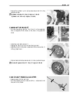
KICK STARTER

• Install the kick starter stopper 


1

 and kick starter guide 


2

.

• Align the punched mark 


A

 on the kick starter with the

punched mark 


B

 on the kick starter shaft.


1

Kick starter lever


3

Kick starter shaft


5

Kick starter return spring


2

Kick starter drive gear


4

Kick starter

Summary of Contents for DR-Z70

Page 1: ...9 9 5 0 0 4 0 0 3 0 0 3 E ...

Page 2: ...RPORATION 2007 This manual has been prepared on the basis of the latest specifications at the time of publi cation If modifications have been made since then differences may exist between the con tent of this manual and the actual motorcycle Illustrations in this manual are used to show the basic principles of operation and work procedures They may not represent the actual motorcycle exactly in de...

Page 3: ...nd the item and page you need COMPONENT PARTS AND WORK TO BE DONE Under the name of each system or unit is its exploded view Work instructions and other service information such as the tightening torque lubricating points and locking agent points are provided Example Front wheel and front brake 1 Front axle 2 Spacer R 3 Dust seal 4 Bearing R 5 Spacer 6 Front wheel rim 7 Bearing L 8 Spring 9 Brake ...

Page 4: ...Measure in voltage range Apply oil Use engine oil unless other wise specified Measure in resistance range Apply molybdenum oil solution mixture of engine oil and SUZUKl MOLY PASTE in a ratio of 1 1 Measure in diode test range Apply SUZUKI SUPER GREASE A or equivalent grease 99000 25010 Measure in continuity test range Apply SUZUKI BOND 1215 or equiva lent bond 99000 31110 Use special tool Apply TH...

Page 5: ...U S A WARNING CAUTION NOTE 1 2 GENERAL PRECAUTIONS 1 2 SUZUKI DR Z70K8 08 MODEL 1 4 SERIAL NUMBER LOCATION 1 4 FUEL AND OIL RECOMMENDATION 1 5 FUEL FOR USA AND CANADA 1 5 FUEL FOR OTHER COUNTRIES 1 5 ENGINE OIL FOR USA 1 5 ENGINE OIL FOR OTHER COUNTRIES 1 5 BREAK IN PROCEDURES 1 5 INFORMATION LABELS 1 6 SPECIFICATIONS 1 7 DIMENSIONS AND DRY MASS 1 7 ENGINE 1 7 DRIVE TRAIN 1 7 CHASSIS 1 8 ELECTRICA...

Page 6: ... stated you must use good judgement and basic mechanical safety principles If you are unsure about how to perform a particular service operation ask a more experienced mechanic for advice GENERAL PRECAUTIONS Proper service and repair procedures are important for the safety of the service mechanic and the safety and reliability of the motorcycle When 2 or more persons work together pay attention to...

Page 7: ...d outside and to the speci fied tightening torque Whenever you remove oil seals gaskets packing O rings locking washers self locking nuts cotter pins circlips and certain other parts as specified be sure to replace them with new ones Also before installing these new parts be sure to remove any left over material from the mating surfaces Never reuse a circlip When installing a new circlip take care...

Page 8: ...ts SERIAL NUMBER LOCATION The frame serial number or V I N Vehicle Identification Number 1 is stamped on the right side of the steering head pipe The engine serial number 2 is located on the right side of the right crankcase These numbers are required especially for registering the machine and ordering spare parts RIGHT SIDE LEFT SIDE ...

Page 9: ... engine oil is not available select an alternative according to the following chart ENGINE OIL FOR OTHER COUNTRIES Oil quality is a major contributor to your engine s performance and life Always select good quality engine oil Use of SF SG or SH SJ in API with MA in JASO Suzuki recommends the use of SAE 10W 40 engine oil If SAE 10W 40 engine oil is not available select an alternative accord ing to ...

Page 10: ...33 1 Noise label c 2 Information label c 3 Fuel caution label c 4 Manual notice Label c 5 General warning label E c c 6 General warning label F c 7 Manufacturer label c 8 Compliance label E c 9 ICES Canada label c 0 EC mark label c A Compliance label E F c Forward Left Front fork E33 E28 Rear fender Right Forward ...

Page 11: ...e 48 0 mm 1 890 in Stroke 37 0 mm 1 457 in Displacement 67 cm 4 1 cu in Compression ratio 9 5 1 Carburetor MIKUNI VM13SH Air cleaner Polyurethane foam element Starter system Electric and kick Lubrication system Wet sump Idle speed 1 600 100 r min DRIVE TRAIN Clutch Wet shoe auto matic centrifugal type Transmission 3 speed constant mesh Gearshift pattern 3 up Primary reduction ratio 3 823 65 17 Fin...

Page 12: ...ke Front tire size 2 50 10 33J tube type Rear tire size 2 50 10 33J tube type ELECTRICAL Ignition type Electronic ignition CDI Ignition timing 15 B T D C at 1 600 r min Spark plug NGK CR7HSA or DENSO U22FSR U Battery 12 V 8 28 kC 2 3 Ah 10 HR Generator Single phase A C generator Main fuse 10 A CAPACITIES Fuel tank including reserve 3 0 L 0 8 0 7 US lmp gal Reserve 0 8 L 0 2 0 2 US lmp gal Engine o...

Page 13: ... PLUG 2 8 SPARK ARRESTER 2 9 FUEL LINE 2 9 ENGINE OIL 2 10 THROTTLE CABLE PLAY 2 11 IDLE SPEED 2 11 CLUTCH 2 11 DRIVE CHAIN 2 12 BRAKES 2 14 TIRES 2 14 SPOKE NIPPLES 2 15 STEERING 2 16 FRONT FORK 2 16 REAR SUSPENSION 2 16 CHASSIS BOLTS AND NUTS 2 17 COMPRESSION PRESSURE CHECK 2 18 COMPRESSION TEST PROCEDURE 2 18 OIL PRESSURE CHECK 2 19 OIL PRESSURE TEST PROCEDURE 2 19 AUTOMATIC CLUTCH INSPECTION 2...

Page 14: ... necessary C Clean R Replace T Tighten Interval Item Initially 1 month Every 6 months Every 12 months Air cleaner element Inspect each time the motorcycle is ridden and clean as necessary Exhaust pipe bolts and muffler mounting nut T T T Valve clearance I I I Spark plug I R Spark arrester C C Fuel line I I I Engine oil R R R Throttle cable I I I Idle speed I I I Clutch I I I Drive chain Clean oil ...

Page 15: ...ted below NOTE Before lubricating each part clean off any rusty spots and wipe off any grease oil dirt or grime Lubricate exposed parts which are subject to rust with a rust preventative spray whenever the motorcycle has been operated under wet or rainy conditions Side stand pivot and spring hook Kick starter lever Brake pedal pivot Throttle cable Drive chain Front brake lever holder ...

Page 16: ... cover 1 Remove the air cleaner element 2 Fill a container with a non flammable cleaning solvent Immerse the air cleaner element in the cleaning solvent and wash it Squeeze the cleaning solvent out of the washed element by pressing it between the palms of both hands do not twist or wring the element or it will develop tears Immerse the element in air filter oil and squeeze the oil out of the eleme...

Page 17: ...he specified torque Exhaust pipe bolt 10 N m 1 0 kgf m 7 0 lb ft Muffler mounting nut 23 N m 2 3 kgf m 16 5 lb ft The open mesh A of the air cleaner element must be faced outside The surest way to accelerate engine wear is to operate the engine without the element or to use a torn ele ment Make sure that the air cleaner is in good condi tion at all times The life of the engine depends largely on t...

Page 18: ...he time of periodic inspection 2 when the valve mechanism is serviced and 3 when the camshaft is dis turbed by removing it for servicing NOTE The piston must be at TDC on the compression stroke in order to check the valve clearance or to adjust valve clear ance The clearance specification is for COLD state To turn the crankshaft for clearance checking and rotate in the normal running direction Val...

Page 19: ...s gauge between the valve stem end and the adjusting screw on the rocker arm If the clearance is out of specification bring it into the speci fied range 09900 20803 Thickness gauge 09917 14910 Valve clearance adjusting driver Valve adjuster lock nut 10 N m 1 0 kgf m 7 0 lb ft After finishing the valve clearance adjustment reinstall the fol lowing items TDC plug 3 70 Generator cover plug 3 70 Camsh...

Page 20: ...l with a pointed end SPARK PLUG GAP Measure the spark plug gap with a thickness gauge Adjust the spark plug gap if necessary Spark plug gap Standard 0 6 0 7 mm 0 024 0 028 in 09900 20803 Thickness gauge ELECTRODE S CONDITION Inspect the worn or burnt condition of the electrodes If it is extremely worn or burnt replace the new spark plug And also replace the plug if it has a broken insulator damage...

Page 21: ... torque Spark arrester bolt 10 N m 1 0 kgf m 7 0 lb ft FUEL LINE Inspect the fuel hose for damage and fuel leakage If any defects are found replace the fuel hose with a new one Before using a spark plug wrench carefully turn the spark plug by finger into the threads of the cylinder head to prevent damage Clean every 6 months A hot muffler can burn you The muffler will be hot enough to burn you for...

Page 22: ...3 0 lb ft Install the oil filler cap 2 Start up the engine and allow it to run about three minutes at idling speed Turn off the engine and wait about three minutes Remove the filler cap 2 and wipe off the oil with a clean rag Holding the motorcycle vertically Insert the filler cap 2 until the threads touch the filler neck but do not to screw the cap in Draw out the filler cap 2 and check the oil l...

Page 23: ...Start the engine turn the throttle stop screw and set the engine idle speed as follows Engine idle speed 1 600 100 r min 09900 26006 Tachometer CLUTCH Loosen the lock nut 1 First turn the release screw 2 clockwise by one turn and turn it counterclockwise until resistance is felt then turn it clock wise by 1 8 turn Tighten the lock nut 1 while holding the release screw 2 Inspect initially at 1 mont...

Page 24: ...Loosen the rear axle nut 1 Tense the drive chain fully by turning both chain adjusters 2 after looseing the lock nuts 3 Count out 21 pins 20 pitch on the chain and measure the distance between the two points If the distance exceeds the service limit the chain must be replaced Drive chain 20 pitch length 259 0 mm 10 20 in NOTE When replacing the drive chain replace the drive chain and sprockets as ...

Page 25: ... chain slack 25 35 mm 1 0 1 4 in After adjusting the drive chain tighten the rear axle nut 3 to the specified torque Rear axle nut 54 N m 5 4 kgf m 39 0 ib ft Recheck the drive chain slack after tightening the axle nut and readjust if necessary Tighten both lock nuts 4 securely CLEANING AND LUBRICATING Clean the drive chain with kerosine After cleaning and drying the chain oil it with a heavy weig...

Page 26: ...tem is properly adjusted While operating the brake check to see that brake lining wear indicator line 1 is within the wear indicator mark 2 on the brake panel If the brake lining wear indicator line 1 is reached the wear indicator mark 2 the brake shoe assembly must be replaced with a new set of shoe 5 7 TIRES TIRE TREAD CONDITION Operating the motorcycle with excessively worn tires will decrease ...

Page 27: ...n tire pressure Front 100 kPa 1 0 kgf cm 14 psi Rear 125 kPa 1 25 kgf cm 18 psi SPOKE NIPPLES Make sure that the nipples are tight If necessary tighten them with a spoke nipple wrench Spoke nipple 2 N m 0 2 kgf m 1 5 lb ft 09940 60113 Spoke nipple wrench The standard tire fitted on this motorcycle is a 2 50 10 33J for front and rear The use of tires other than those specified may cause instability...

Page 28: ... pull forward If play is found adjust the steering 5 18 FRONT FORK Remove the front fork covers 5 3 Inspect the front forks for grease scoring or scratches on the outer surface of the inner tubes Clean or replace any defective parts if necessary REAR SUSPENSION Replace any defective parts if necessary Remove the seat 5 2 Inspect the rear shock absorber for oil leakage and mounting rubbers on rear ...

Page 29: ...e Tighten initially at 1 month and every 6 months thereafter ITEM N m kgf m lb ft 1 Front axle nut 53 5 3 38 5 2 Handlebars set bolts 23 2 3 16 5 3 Front fork upper bracket bolts 45 4 5 32 5 4 Footrest mounting bolts 23 2 3 16 5 5 Rear shock absorber mounting nuts Upper and Lower 50 5 0 36 0 6 Swingarm pivot nut 42 4 2 30 5 7 Brake cam lever nuts Front and Rear 3 0 3 2 0 8 Rear axle nut 54 5 4 39 ...

Page 30: ...d gasket COMPRESSION TEST PROCEDURE NOTE Before testing the engine for compression pressure make sure that the cylinder head nuts are tightened to the specified torque values and the valves are properly adjusted Warm up the engine before testing Make sure that the battery is fully charged Remove the related parts and test the compression pressure in the following manner Remove the spark plug 2 8 I...

Page 31: ...on of the above items OIL PRESSURE TEST PROCEDURE Connect a tachometer to the high tension cord Remove the exhaust pipe cover 1 Remove the main oil gallery plug 2 Install the oil pressure gauge and adaptor to the main oil gal lery Warm up the engine as follows Summer 10 minutes at 2 000 r min Winter 20 minutes at 2 000 r min After warming up the engine increase the engine speed to 3 000 r min obse...

Page 32: ...g temperature Connect a tachometer to the high tension cord Seated on the motorcycle with the motorcycle on level ground increase the engine RPM slowly and note the RPM at which the motorcycle begins to move forward 09900 26006 Tachometer Clutch engagement 1 700 2 100 r min 2 CLUTCH LOCK UP INSPECTION Perform this inspection to determine if the clutch is engaging fully and not slipping Apply the f...

Page 33: ...IRST CLUTCH 3 45 STARTER CLUTCH 3 45 GENERATOR COVER 3 47 CLUTCH COVER 3 47 CRANKCASE 3 49 ENGINE REASSEMBLY 3 52 CRANKSHAFT 3 52 KICK STARTER 3 54 TRANSMISSION 3 55 OIL BREATHER SEPARATOR 3 56 CRANKCASE 3 56 STARTER IDLE GEAR 3 57 CAM CHAIN 3 57 STARTER CLUTCH AND GENERATOR ROTOR 3 57 GEARSHIFT 3 58 OIL PUMP AND DRIVE GEAR 3 60 GEARSHIFTING CLUTCH 3 61 FIRST CLUTCH AND OIL FILTER CASE 3 62 CLUTCH...

Page 34: ...ion adjuster 3 10 3 68 Piston 3 12 3 66 Camshaft 3 22 3 30 ENGINE LEFT SIDE PARTS REMOVAL INSTALLATION Starter idle gear 3 18 3 57 Engine sprocket 3 5 3 6 Generator cover 3 13 3 64 Generator rotor 3 17 3 57 Neutral switch 3 12 3 65 ENGINE RIGHT SIDE PARTS REMOVAL INSTALLATION Muffler 3 3 3 7 Starter motor 3 9 3 70 Kick starter lever 3 9 3 70 Spark plug 3 9 2 8 Gearshiting clutch 3 15 3 61 First cl...

Page 35: ...aner Engine removal is sequentially explained in the following steps Remove the battery 6 6 Remove the fuel tank side cover 5 3 Drain engine oil 2 10 Remove the exhaust pipe bolts 1 Remove the muffler mounting nut 2 and bolt Remove the muffler 3 Remove the exhaust pipe gasket 4 Disconnect the spark plug cap 5 Remove the carburetor 6 ...

Page 36: ...ENGINE 3 4 Disconnect the starter motor coupler 7 Disconnect the generator coupler 8 and neutral switch cou pler 9 Disconnect the ground wire 0 Remove the footrest A Remove the gearshift lever B ...

Page 37: ... Remove the engine sprocket E with the drive chain F by removing the snap ring D NOTE If it is difficult to remove the engine sprocket loosen the axle nut and chain adjusting nuts to provide additional chain slack Remove the engine from the frame ...

Page 38: ...king Once the nuts have been removed they are no longer of any use Engine mounting nut 31 N m 3 1 kgf m 22 5 lb ft Install the engine sprocket 1 with the drive chain Install the snap ring 2 Install the carburetor NOTE Install the clamp as shown in the illustration LH RH The removed snap ring must be replaced with a new one The drive chain joint clip should be attached in the way that the slit end ...

Page 39: ...ighten the muffler mounting nut to the specified torque Muffler mounting nut 23 N m 2 3 kgf m 16 5 lb ft Tighten the footrest mounting bolts to the specified torque Footrest mounting bolt 23 N m 2 3 kgf m 16 5 lb ft Install the gearshift lever as shown The removed gasket must be replaced with a new one to prevent exhaust gas leakage 2 5 mm 0 1 in ...

Page 40: ... cables and hoses Refer to the wire and cable routing sec tions 7 13 Refer to the following sections to adjust the respective items to specification ENGINE OIL 2 10 THROTTLE CABLE PLAY 2 11 ENGINE IDLE SPEED 2 11 DRIVE CHAIN SLACK 2 13 Check for leakage of the engine oil ...

Page 41: ... CRANKCASE BREATHER HOSE Remove the crankcase breather hose SPARK PLUG Remove the spark plug STARTER MOTOR Remove the starter motor Identify the position of each removed part Organize the parts in their respective groups so that they can be reinstalled in their original positions ...

Page 42: ... Turn the crankshaft bring the Top line A on the generator rotor to the center of hole on the generator cover NOTE At the above condition the piston is at TDC of compression stroke and also the mark B on the camshaft sprocket with the concave line C of the cylinder head as shown Remove the cam chain tension adjuster cap 4 ...

Page 43: ...ove the camshaft sprocket washer 7 and camshaft sprocket 8 Remove the cylinder head base bolt Remove the cylinder head nuts diagonally Remove the cylinder head nut gaskets 9 and copper washer 0 Remove the cylinder head assembly A NOTE If the cylinder head does not come off easily lightly tap it with a plastic mallet ...

Page 44: ... not come off easily lightly tap it with a plastic mallet Remove the dowel pins 7 and cylinder gasket 8 PISTON Place a clean rag over the cylinder base to prevent the piston pin circlip from dropping into the crankcase Remove the piston pin circlip 1 Remove the piston pin 2 and piston 3 NEUTRAL SWITCH Remove the neutral switch 1 Remove the neutral switch contact 2 and spring 3 ...

Page 45: ...NGINE GENERATOR COVER Remove the generator cover 1 Remove the dowel pins 2 and gasket 3 CLUTCH COVER Remove the clutch cover 1 Remove the dowel pins 2 and gasket 3 OIL SUMP FILTER Remove the oil sump filter 1 ...

Page 46: ...tool 09920 53740 Clutch sleeve hub holder Remove the oil filter case nut 2 with the special tool 09930 44530 Rotor holder Remove the washer 3 and oil filter case 4 FIRST CLUTCH Remove the clutch shoe assembly 1 and primary drive gear 2 GEARSHIFT CLUTCH Remove the push piece 1 ...

Page 47: ...ssembly 3 OIL PUMP Remove the oil pump 1 Remove the dowel pins 2 OIL PUMP DRIVE GEAR Remove the oil pump drive gear 1 and pin 2 GEARSHIFT CAM STOPPER Remove the gearshift cam bolt 1 and washer 2 Remove the gearshift cam stopper plate 3 and gearshift cam stopper guide 4 ...

Page 48: ...e the gearshift cam pins 5 Remove the gearshift cam stopper 6 GEARSHIFT SHAFT Remove the release ball outer guide 1 Remove the release ball 2 Remove the gearshift shaft 3 and spacer 4 Remove the gearshift arm assembly 5 ...

Page 49: ...am retainer 1 GENERATOR ROTOR AND STARTER CLUTCH Hold the crankshaft with the special tool 09930 44530 Rotor holder Remove the generator rotor nut 1 Remove the generator rotor 2 with the special tool 09930 34951 Rotor remover Remove the key 3 Remove the starter clutch gear plate 4 and starter driven gear 5 ...

Page 50: ...ve the starter idle gear shaft 4 CRANKCASE Remove the crankcase bolts Separate the crankcase with the special tool 09920 13120 Crankcase and shaft remover NOTE Fit the crankcase separating tool so that the tool arms are in parallel with the side of crankcase The crankshaft component should remain in the left crankcase half ...

Page 51: ... dowel pins 1 Remove the oil breather separator 2 TRANSMISSION Remove the gearshift fork shafts 1 and gearshift cam 2 Remove the gearshift fork No 1 3 and No 2 4 Remove the driveshaft assembly 5 and countershaft assem bly 6 ...

Page 52: ...FT Remove the washer 1 Remove the kick starter shaft 2 by turning the shaft Remove the kick starter guide 3 and kick starter stopper 4 CRANKSHAFT Remove the crankshaft with the special tool 09920 13120 Crankcase and shaft remover ...

Page 53: ...ipe 2 Remove the valve clearance inspection caps 3 and cylinder head right cover 4 Pull out the intake and exhaust rocker arm shafts 5 by using an 8 mm thread bolt Identify the position of each removed part Organize the parts in their respective groups i e intake or exhaust so that they can be installed in their original locations ...

Page 54: ...haft 7 Compress the valve spring with the special tools Remove the two cotter halves 8 09916 14510 Valve spring compressor 09916 14521 Attachment 09916 84511 Tweezers Remove the valve spring retainer 9 and valve spring 0 Remove the valve A from the combustion chamber side ...

Page 55: ...shaft contacting surface should be checked Rocker arm I D IN EX Standard 10 003 10 018 mm 0 3938 0 3944 in 09900 20605 Dial calipers CYLINDER HEAD DISTORTION Decarbonize the combustion chamber Inspect the gasketed surface of the cylinder head for distortion with a straightedge and thickness gauge taking a clearance reading at several places as indicated If the largest reading at any position of th...

Page 56: ...uge as shown If the runout exceeds the limit replace the valve Valve stem runout IN EX Service Limit 0 05 mm 0 002 in 09900 20701 Magnetic stand 09900 20607 Dial gauge 1 100 mm 09900 21304 V block 100 mm VALVE HEAD RADIAL RUNOUT Place the dial gauge at right angles to the valve head and measure the valve head radial runout If it measures more than limit replace the valve Valve head radial runout I...

Page 57: ... sure to recheck the deflec tion Valve stem O D Standard IN 4 960 4 975 mm 0 1953 0 1959 in EX 4 945 4 960 mm 0 1947 0 1953 in 09900 20205 Micrometer 0 25 mm NOTE If valve guides have to be removed for replacement after inspecting related parts carry out the steps shown in valve guide servicing below VALVE GUIDE SERVICING Using the valve guide remover drive the valve guide out toward the intake or...

Page 58: ... INSPECTION Visually inspect for valve seat width on each valve face If the valve face has worn abnormally replace the valve Coat the valve seat with a red lead Prussian Blue and set the valve in place Rotate the valve with light pressure Inspect that the transferred red lead Prussian Blue on the valve face is uniform all around and in center of the valve face 09916 10911 Valve lapper set If the s...

Page 59: ...If pitting or wear is present resurface the valve stem end Make sure that the length A is not less than 2 2 mm If this length becomes less than 2 2 mm replace the valve Valve stem end length Service Limit 2 2 mm 0 09 in INTAKE SIDE EXHAUST SIDE Seat angle 15 45 Seat width 0 9 1 1 mm 0 035 0 043 in Valve diameter 22 5 mm 0 89 in 19 0 mm 0 75 in Valve guide I D 5 000 5 012 mm 0 1969 0 1973 in The va...

Page 60: ...EX Standard 157 181 N 16 0 18 5 kgf 35 3 40 8 lbs at length 25 5 mm 1 00 in CAM WEAR Check the camshaft for damage or wear on the cam face Mea sure the cam height H with a micrometer Replace the camshaft assembly if defects is found or cam height H is less than the service limit Cam height H Service Limit IN 27 09 mm 1 067 in EX 26 95 mm 1 061 in 09900 20202 Micrometer 25 50 mm CAMSHAFT BEARING IN...

Page 61: ...or damage If any defects are found replace the cam chain tensioner with a new one REASSEMBLY Install the valve spring seat 1 Apply MOLYBDENUM OIL SOLUTION to the oil seal 2 and press fit it into position P MOLYBDENUM OIL SOLUTION Insert the valve with its stem coated with MOLYBDENUM OIL SOLUTION all around and along the full stem length with out any break P MOLYBDENUM OIL SOLUTION The sealed cover...

Page 62: ...ame manner as described previously 3 Valve spring retainer 4 Cotter 09916 14510 Valve spring compressor 09916 14521 Attachment 09916 84511 Tweezers NOTE Just before installing the camshaft into the cylinder head apply engine oil to the cam faces and inner rase of bearings Install the intake and exhaust rocker arms 5 UP ward Be sure to restore each spring and valve to their original positions Be ca...

Page 63: ...d right cover 3 to the cylinder head Tighten the cylinder head right cover bolts 4 securely INTAKE PIPE Install the intake pipe O ring 1 Apply SUZUKI SUPER GREASE A to the intake pipe O ring 1 X 99000 25010 SUZUKI SUPER GREASE A or equivalent Tighten the intake pipe nuts 2 to the specified torque Intake pipe nut 5 5 N m 0 55 kgf m 4 0 lb ft The removed gasket must be replaced with a new one The re...

Page 64: ...tortion Service Limit 0 05 mm 0 002 in 09900 20803 Thickness gauge CYLINDER BORE Measure the cylinder bore diameter at six places If any one of the measurements exceed the limit overhaul the cylinder and replace the piston with an oversize piston or replace the cylinder Cylinder bore Service Limit 48 105 mm 1 8939 in 09900 20530 Cylinder bore gauge set PISTON AND PISTON PIN PISTON DIAMETER Using a...

Page 65: ...the micrometer If any of the measurements is out of specification replace the piston pin Piston pin O D Service Limit 12 980 mm 0 5110 in 09900 20205 Micrometer 0 25 mm PISTON RING TO GROOVE CLEARANCE Measure the side clearances of the 1st and 2nd piston rings using the thickness gauge If any of the clearances exceeds the limit replace both the piston and piston rings Piston ring to groove clearan...

Page 66: ...ston ring end gap Service Limit 1st 2nd 0 5 mm 0 02 in 09900 20803 Thickness gauge OVERSIZE RING Oversize piston ring The following oversize piston ring is used It bears the following identification number Piston ring 1st and 2nd 0 5 mm 50 Oversize oil ring The following oversize oil ring is used It bears the following identification mark Oil ring 0 5 mm Painted red Oversize side rail Measure the ...

Page 67: ...3 35 ENGINE CAM CHAIN GUIDE INSPECTION Check the cam chain guide for wear or damage If any defects are found replace the cam chain guide with a new one ...

Page 68: ... the conrod small end inside diameter Conrod small end I D Service Limit 13 040 mm 0 5134 in 09900 20605 Dial calipers If the conrod small end bore inside diameter exceeds the limit replace the conrod 1 Oil pump drive gear 3 Crankshaft LH 5 Bearing 2 Crankshaft RH 4 Conrod 6 Crank pin ...

Page 69: ...nkshaft assembly or bring the deflection and side clearance into specifi cation by replacing the worn parts e g conrod big end bearing and crank pin Conrod big end side clearance Service Limit 1 0 mm 0 04 in 09900 20803 Thickness gauge CRANKSHAFT RUNOUT Measure the crankshaft runout with V blocks and dial gauge Crankshaft runout Service Limit 0 08 mm 0 003 in 09900 20607 Dial gauge 1 100 mm 09900 ...

Page 70: ...is anything unusual replace the oil pump REASSEMBLY Reassemble the oil pump in the reverse order of disassembly Apply SUZUKI SUPER GREASE A to the O rings 1 X 99000 25010 SUZUKI SUOER GREASE A or equivalent Install the O rings 1 OIL SUMP FILTER Clean the oil sump filter with compressed air Do not attempt to disassemble the oil pump assembly It is available only as an assembly The removed O rings m...

Page 71: ...d inner surface of the each gear 1 1st driven gear 4 Countershaft 7 2nd drive gear 2 3rd driven gear 5 3rd drive gear 3 Driveshaft 6 Sliding dog Never reuse a snap ring After a snap ring has been removed from a shaft it should be dis carded and a new snap ring must be installed When installing a new snap ring do not expand the end gap larger than required to slip the snap ring over the shaft After...

Page 72: ... snap ring pay attention to the direction of the snap ring Fit the snap ring to the side where the thrust is as shown in the illustration The rounded side should be against the gear surface 1 Countershaft 2 Driveshaft Thrust Sharp edge ...

Page 73: ...f the shifting action If the clearance exceeds the specification replace the fork its respective gear or both Gearshift fork to groove clearance Service Limit No 1 No 2 0 5 mm 0 02 in 09900 20803 Thickness gauge GEARSHIFT FORK GROOVE WIDTH Measure the gearshift fork groove width using the vernier cali pers Gearshift fork groove width Standard No 1 No 2 4 5 4 6 mm 0 177 0 181 in 09900 20101 Vernier...

Page 74: ...d driven plates using vernier calipers If a clutch drive and or driven plate is not within the service limit replace it with a new one Clutch drive and driven plate thickness Service Limit drive A 2 2 mm 0 092 in driven No 1 B 1 72 mm 0 068 in driven No 2 C 2 2 mm 0 092 in 09900 20101 Vernier calipers 1 Push piece 4 Clutch driven plate No 2 7 Clutch pressure plate 2 Clutch sleeve hub 5 Primary dri...

Page 75: ...the reverse order of disas sembly Pay attention to the following points Align the claw 1 of clutch driven plate No 1 2 with the boss 3 of clutch sleeve hub Align the claw 5 of clutch driven plate No 2 4 with the groove 6 of clutch sleeve hub Face the boss of primary driven gear 7 to upper when install ing it Align the claw 8 of clutch driven plate No 1 with the hole 9 of primary driven gear ...

Page 76: ...ve plate 0 face its claw A downward as shown Install the clutch pressure plate B Install the clutch spring C and spacer D Compress the spring with the special tool and install the snap ring 1 09920 33510 Clutch spring compressor The removed snap ring must be replaced with a new one ...

Page 77: ...if the inside diameter exceeds the service limit replace the first clutch housing with a new one First clutch housing l D Service Limit 105 50 mm 4 154 in Inspect each roller and one way clutch retainer for abnormal wear or damage If any defects are found replace them as a set 1 First clutch housing 2 Primary drive gear spacer 3 Washer 4 One way clutch retainer 5 One way clutch spring 6 One way cl...

Page 78: ...gear for wear or damage If any defects are found replace the starter driven gear with a new one REASSEMBLY Reassemble the starter clutch in the reverse order of disassem bly Pay attention to the following points Install the starter clutch in the proper direction as shown Apply engine oil to the starter clutch Apply THREAD LOCK SUPER 1322 to the bolts H 99000 32110 THREAD LOCK SUPER 1322 Holding th...

Page 79: ...hten the generator stator bolts 1 pick up coil set bolts 2 and generator lead wire clamp bolt 3 to the specified torque Generator stator bolt 10 N m 1 0 kgf m 7 0 lb ft Pick up coil set bolt 4 5 N m 0 45 kgf m 3 5 lb ft Generator lead wire clamp bolt 10 N m 1 0 kgf m 7 0 lb ft NOTE Be sure to install the grommet 4 to the generator cover CLUTCH COVER DISASSEMBLY Remove the lock nut 1 and spacer 2 R...

Page 80: ...of disassem bly Pay attention to the following points Install the oil seal 1 and 2 with the special tool 09913 70210 Bearing installer set Apply SUZUKI SUPER GREASE A to the lip of the oil seal X 99000 25010 SUZUKI SUPER GREASE A or equivalent Install the O ring 3 The removed oil seals must be replaced with new ones The removed O ring must be replaced with a new one ...

Page 81: ...bearings are in the crank case Replace the bearing in the following procedure if there is any thing unusual RIGHT CRANKCASE BEARING REMOVAL Remove the bearing retainer 1 Remove the bearings with the special tools 09921 20240 Bearing remover set Bearing 2 22 Attachment Bearing 3 17 Attachment Bearing 4 12 Attachment LEFT CRANKCASE BEARING REMOVAL Remove the bearings with the special tools 09921 202...

Page 82: ...cial tool 09913 70210 Bearing installer set Bearing 1 52 Attachment Bearing 2 40 Attachment Bearing 3 35 Attachment NOTE When installing the bearing stamped mark on bearing must face outside Apply a small quantity of THREAD LOCK SUPER 1322 to the bearing retainer screws H 99000 32050 THREAD LOCK SUPER 1322 Tighten the screws 4 securely The removed bearings must be replaced with new ones ...

Page 83: ...rk on bearing must face outside 09913 70210 Bearing installer set LEFT CRANKCASE OIL SEAL INSTALLATION Install the oil seals 1 to the left crankcase with the special tool Apply SUZUKI SUPER GREASE A to the oil seal lip X 99000 25010 SUZUKI SUPER GREASE A or equivalent 09913 70210 Bearing installer set The removed bearings must be replaced with new ones The removed oil seals must be replaced with n...

Page 84: ...inner race of the right crankshaft bearing Place the removed shim 1 on the right crankshaft Put the plasti gauge special tool 2 cut out about 10 mm on the shim as shown 09900 22301 Plasti gauge Install the right crankcase and tighten the crankcase bolts to the specified torque Crankcase bolt 10 N m 1 0 kgf m 7 0 lb ft Remove the crankcase bolts Separate the crankcase with the special tool 3 18 Mea...

Page 85: ...t LIST OF SHIMS Part number Shim thickness 09181 20187 0 60 mm 0 024 in 09181 20009 0 65 mm 0 026 in 09181 20188 0 70 mm 0 028 in 09181 20189 0 75 mm 0 030 in 09181 20190 0 80 mm 0 031 in 09181 20191 0 85 mm 0 033 in 09181 20192 0 90 mm 0 035 in 09181 20193 0 95 mm 0 037 in 09181 20195 1 00 mm 0 039 in 09181 20197 1 05 mm 0 041 in 09181 20200 1 10 mm 0 043 in 09181 20202 1 15 mm 0 045 in 09181 202...

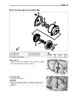
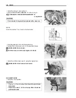
Page 86: ...rter stopper 1 and kick starter guide 2 Align the punched mark A on the kick starter with the punched mark B on the kick starter shaft 1 Kick starter lever 3 Kick starter shaft 5 Kick starter return spring 2 Kick starter drive gear 4 Kick starter ...

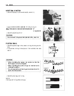
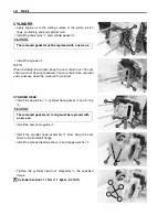
Page 87: ... and kick starter spring hook end 3 onto the left crankcase boss TRANSMISSION Install the countershaft assembly 1 and driveshaft assembly 2 Install the gearshift forks 3 Gearshift fork No 1 4 Gearshift fork No 2 Install the gearshift cam 5 Install the gearshift fork shafts 6 ...

Page 88: ...el pins 1 into the left half of the crankcase Apply engine oil to the conrod big end and transmission gears Apply SUZUKI BOND 1215 to the mating surface of the right crankcase as shown E 99000 31110 SUZUKI BOND 1215 Tighten the crankcase bolts to the specified torque Crankcase bolt 10 N m 1 0 kgf m 7 0 lb ft NOTE After the crankcase bolts have been tightened make sure that the crankshaft countersh...

Page 89: ...kshaft sprocket STARTER CLUTCH AND GENERATOR ROTOR Apply engine oil to the starter driven gear bearing 1 and crankshaft 2 Install the starter driven gear 3 key 4 and starter clutch gear plate 5 NOTE Degrease the tapered portion of the generator rotor and also the crankshaft Use nonflammable cleaning solvent to wipe off oily or greasy matter to make these surfaces completely dry Removed snap ring m...

Page 90: ...r rotor nut 55 N m 5 5 kgf m 40 0 lb ft GEARSHIFT 1 Gearshift cam guide 9 Release arm 2 Gearshift cam plate 0 Release ball outer guide 3 Gearshift pin A Release ball 4 Gearshift cam B Gearshift shaft 5 Gearshift stopper C Gearshift arm lever 6 Gearshift fork No 1 D Gearshift lever 7 Gearshift fork No 2 A Gearshift arm stopper bolt ITEM N m kgf m lb ft 8 Neutral switch A 19 1 9 13 5 ...

Page 91: ...1 and tighten it to the specified torque H 99000 32110 THREAD LOCK SUPER 1322 Gearshift arm stopper bolt 19 N m 1 9 kgf m 13 5 lb ft Install the washer 2 gearshift arm assembly 3 gearshift spacer 4 and gearshift shaft 5 Install the release ball 6 NOTE Face the lug A of the release ball 6 to the outside Install the release ball outer guide 7 as shown ...

Page 92: ... cam bolt 5 Install the washer 1 return spring 2 gearshift cam stopper 3 gearshift cam stopper bolt 4 OIL PUMP AND DRIVE GEAR Install the pin 1 and oil pump drive gear 2 Install the dowel pins 3 Apply SUZUKI SUPER GREASE A to the O rings 4 Install the O rings 4 X 99000 25010 SUZUKI SUPER GREASE A or equivalent The removed O rings must be replaced with new ones ...

Page 93: ...1 ENGINE Install the oil pump 5 GEARSHIFTING CLUTCH Install the gearshifting clutch assembly 1 Install the snap ring 2 Install the clutch push piece 3 The removed snap ring must be replaced with a new one ...

Page 94: ...oves A diago nally to the crankshaft oil hole B as shown OIL FILTER CASE Install the oil filter case 1 1 Oil filter cover 4 Primary drive gear 2 Oil filter case A Oil filter case nut ITEM N m kgf m lb ft 3 Clutch shoe assembly A 63 6 3 45 5 Align the crankshaft oil hole B with the oil filter case groove A ...

Page 95: ...en the oil filter case nut 4 to the specified torque 09930 44530 Rotor holder Oil filter case nut 63 N m 6 3 kgf m 45 5 lb ft Install the oil filter case cover 5 using the special tool 09920 53740 Clutch sleeve hub holder OIL SUMP FILTER Install the oil sump filter The removed O ring must be replaced with a new one The lip A of the oil sump filter should be positioned downward The thinner side B o...

Page 96: ...until resistance is felt then turn it clock wise by 1 8 turn Tighten the lock nut 1 while holding the release screw 2 GENERATOR COVER Install the dowel pins 1 and gasket 2 Install the generator cover 3 Tighten the generator cover bolts to the specified torque Generator cover bolt 10 N m 1 0 kgf m 7 0 lb ft NOTE Install the lead wire clamp with the bolt A The removed gasket must be replaced with a ...

Page 97: ...ing and 1st ring To install the oil ring fit the spacer 1 first and then the side rails 2 Install the 2nd ring and 1st ring NOTE 2nd ring and 1st ring differ in shape The removed O ring must be replaced with a new one When installing the spacer be careful so that the both edges are not overlapped When installing the piston rings be careful not to damage the piston Do not expand the piston ring exc...

Page 98: ...he piston pin P MOLYBDENUM OIL SOLUTION NOTE Install the piston with the mark A on the piston head facing towards the exhaust side Place a clean rag over the cylinder base to prevent the piston pin circlip from dropping into the crankcase Install the circlip 1 NOTE The circlip end gap should not be aligned with the piston pin bore cutaway 2nd ring Lower side rail Upper side rail 1st ring Spacer Th...

Page 99: ...ket and crankcase when the crankshaft is rotated CYLINDER HEAD Install the dowel pins 1 cylinder head gasket 2 and O ring 3 Install the cam chain guide 4 Install the cylinder head assembly 5 after hang the cam chain to the camshaft flange Install the cylinder head washers 6 and copper washer 7 Tighten the cylinder head nut diagonally to the specified torque Cylinder head nut 11 N m 1 1 kgf m 8 0 l...

Page 100: ... with the center of the hole in the generator cover Install the camshaft sprocket 1 Engage the cam chain onto the camshaft sprocket Align the mark B of the cam sprocket with the concave line C of the cylinder head Tighten the camshaft sprocket bolts 2 to the specified torque Camshaft sprocket bolt 11 N m 1 1 kgf m 8 0 lb ft CAM CHAIN TENSION ADJUSTER Apply engine oil to the push rod Turn the adjus...

Page 101: ...in tension adjuster rotate the crankshaft some turns and recheck the positions of the camshaft sprocket VALVE CLEARANCE INSPECTION CAP AND CAMSHAFT SPROCKET COVER Apply SUZUKI SUPER GREASE A to the O ring X 99000 25010 SUZUKI SUPER GREASE A or equivalent Apply SUZUKI SUPER GREASE A to the O ring X 99000 25010 SUZUKI SUPER GREASE A or equivalent The removed gasket must be replaced with a new one up...

Page 102: ...1 N m 1 1 kgf m 8 0 lb ft STARTER MOTOR Install the O ring 1 to the starter motor Apply SUZUKI SUPER GREASE A to the O ring 1 X 99000 25010 SUZUKI SUPER GREASE A or equivalent Install the starter motor 2 to the engine Tighten the starter motor mounting bolts to the specified torque Starter motor mounting bolt 10 N m 1 0 kgf m 7 0 lb ft KICK STARTER LEVER Install the kick starter lever 1 The remove...

Page 103: ...4 5 CONSTRUCTION 4 5 SPECIFICATIONS 4 6 I D NO LOCATION 4 6 REMOVAL 4 6 DISASSEMBLY 4 7 CLEANING 4 9 INSPECTION AND ADJUSTMENT 4 10 REASSEMBLY AND REMOUNTING 4 11 LUBRICATION SYSTEM 4 13 OIL PRESSURE 4 13 OIL FILTER CASE 4 13 OIL SUMP FILTER 4 13 OIL PUMP 4 13 ENGINE LUBRICATION SYSTEM CHART 4 13 Gasoline must be handled carefully in an area well ventilated and away from fire or sparks ...

Page 104: ...FUEL SYSTEM 4 2 4 6 FUEL TANK AND FUEL VALVE CONSTRUCTION 1 Fuel tank breather hose 4 Fuel valve 2 Fuel tank cap 5 Fuel hose ITEM N m kgf m lb ft 3 Fuel tank A Fuel valve bolt A 4 5 0 45 3 0 ...

Page 105: ...Remove the fuel tank cap 3 and fuel tank upper cover 4 Remove the fuel valve 5 FUEL FILTER INSPECTION AND CLEANING If the fuel filter is dirty with sediment or rust fuel will not flow smoothly and loss in engine power may result Clean the fuel filter with compressed air and check the fuel filter for cracks Gasoline is highly flammable and explosive Keep heat spark and flame away ...

Page 106: ... Install the new fuel valve gasket 1 Tighten the fuel valve bolts to the specified torque Fuel valve bolt 4 5 N m 0 45 kgf m 3 5 lb ft Install the fuel tank and tighten its bolts securely Install the fuel hose and fuel tank breather hose 7 15 Reinstall the seat and fuel tank cover 5 3 The removed gasket must be replaced with a new one to prevent fuel leakage ...

Page 107: ...2 Gasket 0 Air screw H Pilot jet 3 Spring A O ring I Float 4 Spring seat B Throttle stop screw J Gasket 5 O ring C Needle valve seat K Float chamber 6 Jet needle D Needle L Overflow hose 7 Throttle valve E Needle jet M Drain plug 8 Starter plunger F Needle jet holder N Air vent hose ...

Page 108: ...connect the starter cable 3 Loosen the intake pipe clamp screw 4 Remove the carburetor mounting bolts nuts 5 Remove the carburetor assembly 6 ITEM SPECIFICATION Carburetor type MIKUNI VM13SH Bore size 13 mm 0 5 in I D No 14H0 Idle r min 1 600 100 r min Float height 23 4 1 0 mm 0 92 0 04 in Main jet M J 55 Jet needle J N 3L43 Needle jet N J E 5M Pilot jet P J 17 5 Air screw A S PRE SET 2 turns back...

Page 109: ...r plunger 1 Remove the throttle valve 2 and spring 3 from the throttle cable Remove the spring seat 4 Remove the jet needle 5 washer 6 and spring 7 from the throttle valve 2 Remove the air vent hose 7 and overflow hose 8 Remove the float chamber 9 ...

Page 110: ...emove the float B Remove the needle valve C Remove the needle valve seat D Remove the main jet E needle jet holder F and needle jet G Remove the pilot jet H Remove the throttle stop screw I Remove the O ring J washer K and spring L from the throttle stop screw I ...

Page 111: ... and then backing it out the same number of turns counted during disassembly Install new plug by tapping it into place with a punch CLEANING Clean all jets with a spray type carburetor cleaner and dry them with compressed air Clean all circuits of the carburetor thoroughly not just the perceived problem area Clean the circuits in the carburetor body with a spray type cleaner and allow each circuit...

Page 112: ...ill occur Conversely if the needle valve sticks the gasoline will not flow into the float chamber Clean the float chamber and float parts with gasoline If the needle valve is worn as shown in the illustration replace the needle valve assembly with a new one Clean the fuel pas sage of the mixing chamber with compressed air FLOAT HEIGHT ADJUSTMENT To check the float height turn the carburetor upside...

Page 113: ...of removal and disassembly Pay attention to the following points Install the needle valve seat 1 Install the throttle stop screw 2 Install the gasket 3 The removed O ring must be replaced with a new one The removed O rings must be replaced with new ones The removed gasket must be replaced with a new one ...

Page 114: ...hten the carburetor mounting bolts 7 to the specified torque Carburetor mounting bolt 10 N m 1 0 kgf m 7 0 lb ft After remounting the carburetor perform the following Install the fuel hose 7 15 Check for fuel leakage Engine idle r min adjustment 2 11 Throttle cable play adjustment 2 11 Align the slit B of the throttle valve 4 with the projec tion C on the carburetor body The removed O rings must b...

Page 115: ... OIL PUMP 3 38 ENGINE LUBRICATION SYSTEM CHART CYLINDER HEAD CYLINDER WALL CONROD SMALL END CONROD BIG END BEARING PRIMARY DRIVE GEAR FIRST CLUTCH CYLINDER OIL ORIFICE OIL PUMP OIL SUMP FILTER CAMSHAFT CAM FACE CAM CHAIN CLUTCH COVER OIL FILTER CASE CRANKSHAFT INTAKE ROCKER ARM EXHAUST ROCKER ARM ...

Page 116: ...RONT FORK 5 10 CONSTRUCTION 5 10 REMOVAL 5 11 INSPECTION 5 12 REASSEMBLY AND REMOUNTING 5 13 STEERING 5 15 CONSTRUCTION 5 15 REMOVAL AND DISASSEMBLY 5 15 INSPECTION 5 17 REASSEMBLY AND REMOUNTING 5 18 REAR WHEEL AND REAR BRAKE 5 21 CONSTRUCTION 5 21 REMOVAL 5 22 INSPECTION AND DISASSEMBLY 5 23 REASSEMBLY AND REMOUNTING 5 23 REAR SUSPENSION 5 26 CONSTRUCTION 5 26 REMOVAL AND DISASSEMBLY 5 27 INSPEC...

Page 117: ...ick out toward the head so that the pawls 2 close Insert the fastener into the installation hole NOTE To prevent the pawl 2 from damage insert the fastener all the way into the installation hole Push in the head of center piece until it becomes flush with the fastener outside face REMOVAL SEAT Remove the seat 1 REAR FENDER AND FRAME COVER Remove the rear fender 1 and frame covers 2 ...

Page 118: ...e the fuel tank upper cover 5 NOTE Install the fuel tank cap after removing the fuel tank upper cover FRONT NUMBER PLATE Remove the front number plate 1 Hook point FRONT FENDER Remove the front number plate Above Remove the front fender 1 FRONT FORK COVER Remove the front fork cover 1 REASSEMBLY Reassemble the exterior parts in the reverse order of removal ...

Page 119: ...nt brake cable lock nut 2 Remove the spring 3 front brake cable 4 and pin 5 Remove the front axle nut 6 1 Front axle 8 Spring 2 Spacer R 9 Brake shoe 3 Dust seal 0 Brake camshaft 4 Bearing R A Brake panel 5 Spacer B Brake cam lever ITEM N m kgf m lb ft 6 Front wheel rim A Front axle nut A 53 5 3 38 5 7 Bearing L B Brake cam lever nut B 3 0 3 2 0 ...

Page 120: ...er 8 Remove the front wheel with the front brake panel Remove the front brake panel 9 Remove the spring 0 and brake shoes A Remove the brake cam lever bolt and nut B Remove the brake cam lever C Remove the washer D O ring E and brake camshaft F Make sure that the motorcycle is securely supported ...

Page 121: ... the adapter Remove the bearing 09941 50111 Bearing remover FRONT AXLE Measure the axle runout using the dial gauge If the runout exceeds the service limit replace the axle 09900 20607 Dial gauge 1 100 mm 09900 20701 Magnetic stand 09900 21304 V block set 100 mm Front axle runout Service Limit 0 25 mm 0 010 in WHEEL Make sure that the wheel rim runout axial and radial does not exceed the service l...

Page 122: ...ake drum I D Service Limit 80 7 mm 3 18 in BRAKE SHOES Inspect the brake shoes wear or damage If they are worn or damaged replace them with new ones REASSEMBLY Reassemble and install the front wheel in the reverse order of removal and disassembly Pay attention to the following points FRONT WHEEL Apply SUZUKI SUPER GREASE A to the wheel bearings X 99000 25010 SUZUKI SUPER GREASE A or equivalent Rep...

Page 123: ...70210 Bearing installer set Apply SUZUKI SUPER GREASE A to the dust seal lip X 99000 25010 SUZUKI SUPER GREASE A or equivalent FRONT BRAKE Apply SUZUKI SUPER GREASE A to the camshaft X 99000 25010 SUZUKI SUPER GREASE A or equivalent The sealed cover of the bearing must face outside The removed bearings must be replaced with new ones The removed dust seal must be replaced with a new one LH RH LH Re...

Page 124: ...UZUKI SUPER GREASE A or equivalent REMOUNTING Remount the front wheel in the reverse order of removal Pay attention to the following points Align the projection 3 on the left fork leg with the slot 4 on the brake panel Move the front fork up and down 4 or 5 times Tighten the front axle nut to the specified torque Front axle nut 53 N m 5 3 kgf m 38 5 lb ft Adjust the front brake lever play 2 14 The...

Page 125: ...5 10 CHASSIS FRONT FORK CONSTRUCTION 1 Spring joint 3 Front fork spring 2 Stopper rubber 4 Inner tube ...

Page 126: ...AL Remove the front number plate 5 3 Remove the front fork cover 5 3 Remove the front wheel 5 4 Remove the dust seal 1 Remove the snap ring 2 Remove the front fork upper bracket 3 Remove the inner tube 4 with inner parts ...

Page 127: ...rter than the ser vice limit replace it with a new one Front fork spring free length Service Limit 154 mm 6 1 in STOPPER Inspect the stopper wear or damage If defects are found replace the damper with a new one INNER TUBE Inspect the inner tube sliding surface for any scuffing If any defects are found replace the inner tube with a new one Do not remove the pin 4 ...

Page 128: ...wing points Install the front fork spring 1 stoppers 2 and spring joint 3 Install the front fork spring NOTE The close pitch end A of spring must face downward Apply SUZUKI SUPER GREASE A approx 40 ml to the inner parts and spring X 99000 25010 SUZUKI SUPER GREASE A or equivalent Wash the removed parts with cleaning solvent before reassembly Downward ...

Page 129: ...en the front fork upper bracket bolts 6 to the specified torque Front fork upper bracket bolt 45 N m 4 5 kgf m 32 5 lb ft Install the front wheel and brake 5 9 Install the front number plate 5 3 After installing the snap ring always insure that it is completely seated in its groove and securely fitted Outer tube Snap ring Rounded part Inner tube ...

Page 130: ...ve the front wheel and brake 5 4 1 Front fork upper bracket 7 Inner race lower 2 Steering stem nut 8 Outer race lower 3 Dust seal 9 Front fork outer tube 4 Outer race upper 0 Handlebars ITEM N m kgf m lb ft 5 Steering bearing A Front fork upper bracket bolt A 45 4 5 32 5 6 Inner race upper B Handlebars set bolt B 23 2 3 16 5 ...

Page 131: ...le case 2 and throttle grip 3 Remove the handlebars 4 Remove the front fork upper bracket 5 Remove the steering stem nut 6 using the special tool 09940 14911 Steering nut socket wrench NOTE Hold the front fork by hand to prevent falling Remove the dust seal 7 ...

Page 132: ...Race wear and brinelling Bearing wear or damage Distortion of the steering stem If any abnormal condition are found replace defective parts with new ones Remove the lower outer race using a chisel Drive out the upper and lower inner races using a suitable bar The removed outer race must be replaced with a new one The removed inner race must be replaced with a new one ...

Page 133: ...y SUZUKI SUPER GREASE A to the upper and lower bearings X 99000 25010 SUZUKI SUPER GREASE A or equivalent STEERING STEM Tighten the steering stem nut 1 at 45 N m 4 5 kgf m 32 5 lb ft Turn the steering stem five or six times to the left and right Loosen the steering stem nut 1 8 1 4 of a turn A 09940 14911 Steering nut socket wrench NOTE This adjustment will vary from motorcycle to motorcycle Make ...

Page 134: ...cable Apply SUZUKI SUPER GREASE A to the throttle cable end X 99000 25010 SUZUKI SUPER GREASE A or equivalent When installing the throttle case align the throttle cable holder edge B with the throttle case C Align the projection D of the throttle case with the hole E on the handlebars NOTE Tighten the upper screw first and then lower screw to screw the throttle case ...

Page 135: ...number plate 5 3 NOTE Hold the front fork legs move them back and forth and make sure that the steering is not loose Handlebars Handle grip bond After performing the adjustment and installing the handlebars rock the front wheel assembly forward and backward to ensure that there is no play and that the procedure was accomplished correctly Finally check to make sure that the steering stem moves free...

Page 136: ...r axle spacer A Brake camshaft 3 Rear sprocket B Brake panel 4 Dust seal C Brake cam lever 5 Bearing D Rear axle 6 Spacer A Rear axle nut ITEM N m kgf m lb ft 7 Rear wheel rim B Rear sprocket bolt A 54 5 4 39 0 8 Rear brake rod C Rear brake cam lever nut B 27 2 7 19 5 9 Spring C 3 0 3 2 0 ...

Page 137: ...r wooden block Remove the rear axle nut 3 and rear axle 4 Disengage the drive chain 5 from the rear sprocket Remove the rear wheel with the rear brake panel Remove the rear brake panel 6 Remove the rear axle spacer 7 Remove the rear sprocket 8 by removing the mounting nuts and bolts Remove the dust seal 9 using special tool 09913 50121 Oil seal remover ...

Page 138: ...ar sprocket teeth for wear If they are worn replace the sprocket and drive chain A Normal wear B Excessive wear REASSEMBLY AND REMOUNTING Reassemble and remount the rear wheel in the reverse order of removal and disassembly Pay attention to the following points REAR WHEEL Apply SUZUKI SUPER GREASE A to the wheel bearings X 99000 25010 SUZUKI SUPER GREASE A or equivalent ...

Page 139: ...SUPER GREASE A to the dust seal lip X 99000 25010 SUZUKI SUPER GREASE A or equivalent Install the rear sprocket and tighten the bolts to the specified torque Rear sprocket bolt 27 N m 2 7 kgf m 19 5 lb ft NOTE The stamped mark A on the rear sprocket should face to the outside The sealed cover of the bearing must face outside The removed bearings must be replaced with new ones The removed dust seal...

Page 140: ... on the swingarm with the slot 2 on the brake panel Tighten the rear axle nut to the specified torque Rear axle nut 54 N m 5 4 kgf m 39 0 lb ft Adjust the drive chain slack after installing the rear wheel 2 13 Adjust the rear brake pedal free travel 2 14 ...

Page 141: ...REAR SUSPENSION CONSTRUCTION 1 Rear shock absorber 5 Chain buffer 2 Swingarm pivot shaft A Swingarm pivot nut ITEM N m kgf m lb ft 3 Bushing B Rear shock absorber mounting nut A 42 4 2 30 5 4 Swingarm B 50 5 0 36 0 ...

Page 142: ...at 5 3 Remove the rear shock absorber mounting nut upper and lower Remove the rear shock absorber 1 Remove the spacers 2 and bushings 3 SWINGARM Remove the engine sprocket cover 1 Remove the rear wheel and brake 5 22 Remove the drive chain 2 Remove the swingarm pivot nut 3 Remove the swingarm pivot shaft 4 and swingarm 5 ...

Page 143: ...oil leakage or damages are found replace the rear shock absorber with a new one CHAIN BUFFER Inspect the chain buffer for damage If any defects are found replace the chain buffer with a new one SWINGARM BUSHING Inspect the swingarm bushing for damage If any defects are found replace the swingarm bushing with a new one Do not attempt to disassemble the rear shock absorber It is unserviceable ...

Page 144: ... the bushing 2 Using an appropriate size steel tubes and vise install the swingarm bushing NOTE Align the surface A of bushing 3 with swingarm inner surface 4 SWINGARM Inspect the swingarm for damage If any defects are found replace the swingarm with a new one ...

Page 145: ...Y AND REMOUNTING Reassemble and remount the swingarm in the reverse order of removal and disassembly Pay attention to the following points Install the swingarm Tighten the swingarm pivot nut to the specified torque Swingarm pivot nut 42 N m 4 2 kgf m 30 5 lb ft Tighten the rear shock absorber mounting nuts to the speci fied torque Rear shock absorber mounting nut 50 N m 5 0 kgf m 36 0 lb ft After ...

Page 146: ...AL COMPONENTS 6 4 CHARGING SYSTEM 6 5 TROUBLESHOOTING 6 5 INSPECTION 6 6 STARTER SYSTEM 6 9 TROUBLESHOOTING 6 9 STARTER MOTOR REMOVAL 6 10 STARTER MOTOR DISASSEMBLY 6 11 STARTER MOTOR INSPECTION 6 12 STARTER MOTOR REASSEMBLY AND INSTALLATION 6 13 STARTER RELAY INSPECTION 6 15 IGNITION SYSTEM 6 16 TROUBLESHOOTING 6 16 INSPECTION 6 18 SWITCHES 6 20 BATTERY 6 21 SPECIFICATIONS 6 21 INITIAL CHARGING 6...

Page 147: ...al to be deformed possibly resulting in poor electrical contact Before refitting the sealed coupler make sure seal rubber is positioned properly The seal rubber may possibly come off the position during disconnecting work and if the coupler is refitted with the seal rubber improperly positioned it may result in poor water sealing CLAMP Clamp the wire harness at such positions as indicated in WIRIN...

Page 148: ...ttery Be sure to recharge the battery in a well ventilated and open area Note that the charging system for the MF battery is different from that of a conventional battery Do not replace the MF battery with a conventional battery WIRING PROCEDURE Properly route the wire harness according to the WIRING HARNESS ROUTING section 7 11 USING THE MULTI CIRCUIT TESTER Properly use the multi circuit tester ...

Page 149: ... 4 ELECTRICAL SYSTEM LOCATION OF ELECTRICAL COMPONENTS Regulator rectifier Generator Fuse 10 A Battery Starter relay CDI unit Starter motor Ignition coil Ignition switch Starter button Engine stop switch ...

Page 150: ... the battery terminals 6 6 Is the regulated voltage OK Step 3 1 Measure the resistance of the generator coil 6 7 Is the resistance of generator coil OK Step 4 1 Measure the generator no load performance 6 7 Is the generator no load performance OK YES Remove accessories NO Go to Step 2 YES Faulty battery Abnormal driving condition NO Go to Step 3 YES Go to Step 4 NO Faulty generator coil Disconnect...

Page 151: ...unning at 5 000 r min Measure the DC voltage between the and battery termi nals using the multi circuit tester If the voltage is not within the specified value inspect the generator and regulator rectifier 6 7 and 8 NOTE When making this test be sure that the battery is in fully charged condition 09900 25008 Multi circuit tester set W Tester knob indication Voltage Regulated voltage Charging outpu...

Page 152: ... Ω Generator coil resistance 0 6 2 0 Ω Black Red Ground GENERATOR NO LOAD PERFORMANCE Disconnect the regulator rectifier coupler 1 Start the engine and keep it running at 5 000 r min Measure the voltage between the B R wire of regulator rectifier coupler and ground using the multi circuit tester If the tester reads under the specified value replace the genera tor with a new one 09900 25008 Multi c...

Page 153: ...indicated in the table below If the voltage is not within the specified value replace the regulator rectifier with a new one 09900 25008 Multi circuit tester set Tester knob indication Diode test Unit V 1 4 V and more tester s battery voltage NOTE If the tester reads 1 4 V and below when the tester probes are not connected replace its battery Tester probe Tester probe A B C A B 1 3 1 6 C 0 9 1 4 ...

Page 154: ...ot use thin wire because a large amount of current flows Does the starter motor run Step 3 1 Measure the starter relay voltage at the starter relay coupler between Y G and Bl when the starter button is pushed Is the voltage OK YES Go to Step 2 NO Go to Step 3 YES Faulty starter relay Loose or disconnected starter motor lead wire Loose or disconnected between starter relay and battery terminal NO F...

Page 155: ... OK Starter motor runs but does not crank the engine Check the starter clutch 3 45 STARTER MOTOR REMOVAL Remove the exhaust pipe cover 1 Disconnect the starter motor coupler 2 Remove the starter motor 3 and ground wire 4 YES Poor contact of the starter relay NO Faulty starter relay ...

Page 156: ...ELECTRICAL SYSTEM 6 11 STARTER MOTOR DISASSEMBLY Remove the O ring 1 Remove the housing end 2 1 O ring 2 Housing end 3 Armature 4 Starter motor case ...

Page 157: ...s than 3 5 mm 0 14 in If this length becomes less than 3 5 mm 0 14 in replace the housing end assembly Starter motor brush length Service Limit 3 5 mm 0 14 in COMMUTATOR Inspect the commutator for discoloration abnormal wear or undercut A If abnormal wear is found replace the armature with a new one If the commutator surface is discolored polish it with 400 sand paper and wipe it using a clean dry...

Page 158: ...al lip for damage or leakage If any defects are found replace the housing end assembly BUSH Check the bush for wear and damage If any defects are found replace the starter motor case STARTER MOTOR REASSEMBLY AND INSTALLATION Reassemble and installation the starter motor in the reverse order of disassembly Pay attention to the following points Apply SUZUKI SUPER GREASE A to the lip of the oil seal ...

Page 159: ...PER GREASE A to the O ring X 99000 25010 SUZUKI SUPER GREASE A or equivalent Install the starter motor and ground wire 5 Tighten the starter motor mounting bolts 6 to the specified torque Starter motor mounting bolt 10 N m 1 0 kgf m 7 0 lb ft The removed O ring must be replaced with a new one The removed O rings must be replaced with new ones The removed O ring must be replaced with a new one ...

Page 160: ...ound the relay is OK 09900 25008 Multi circuit tester set Tester knob indication Continuity test Measure the relay coil resistance between the A and B termi nals using the multi circuit tester If the resistance is not within the specified value replace the starter relay with a new one 09900 25008 Multi circuit tester set V Tester knob indication Resistance Ω Starter relay resistance 70 90 Ω Do not...

Page 161: ... system couplers Step 2 1 Measure the battery voltage between input lead wires O W and B W at the CDI unit with the ignition switch in the ON position Is the voltage OK YES Go to Step 2 NO Poor connection of couplers YES Go to Step 3 NO Faulty ignition switch Faulty wire harness Faulty engine stop switch Poor connection of related circuit couplers Generator Ignition coil B W B W Spark plug Battery...

Page 162: ... up coil peak voltage and pick up coil resistance 6 19 and 20 NOTE The pick up coil peak voltage inspection is applicable only with the multi circuit tester and peak volt adaptor Is the peak voltage and resistance OK YES Go to Step 4 NO Go to Step 5 YES Go to Step 5 NO Faulty spark plug YES Go to Step 6 NO Poor connection of the ignition coil Faulty ignition coil YES Faulty CDI unit Open or short ...

Page 163: ...res 09900 25008 Multi circuit tester set Turn the ignition switch to the ON position Push the starter button and allow the engine to crank for a few seconds and then measure the ignition coil primary peak volt age Repeat the above procedure a few times and measure the highest ignition coil primary peak voltage W Tester knob indication Voltage Ignition coil primary peak voltage 150 V and more If th...

Page 164: ...nnect the generator coupler 1 Measure the pick up coil peak voltage in the following proce dure Connect the multi circuit tester with the peak volt adaptor as follows Probe Black Blue lead wire Probe Ground 09900 25008 Multi circuit tester set Turn the ignition switch to the ON position Push the starter button and allow the engine for a few sec onds and then measure the pick up coil peak voltage R...

Page 165: ... up coil resistance 150 240 Ω When engine is cold SWITCHES Measure each switch for continuity using the multi circuit tester If there is no continuity replace the respec tive switch with a new one Generator B Bl generator coupler WIRE COLOR Bl Blue R Red O Orange O W Orange with White tracer Y G Yellow with Green tracer NEUTRAL SWITCH Bl Graund ON OFF Color Position ENGINE STOP SWITCH O O W OFF RU...

Page 166: ...ely use the removed caps 2 as the sealed caps of battery filler holes Do not remove or pierce the sealed areas 3 of the electrolyte container Insert the nozzles of the electrolyte container 4 into the bat tery s electrolyte filler holes holding the container firmly so that it does not fall Take precaution not to allow any of the fluid to spill Make sure air bubbles 5 are coming up each electrolyte...

Page 167: ...urface of the battery container If any signs of cracking or electrolyte leakage from the sides of the battery have occurred replace the battery with a new one If the battery terminals are found to be coated with rust or an acidic white powdery substance then this can be cleaned away with sandpa per Never use anything except the specified battery Once the caps have been installed to the battery do ...

Page 168: ... multi circuit tester If the battery voltage is 12 5 V or less recharge the battery again If battery voltage is still 12 5 V or less after recharging replace the battery with a new one When the motorcycle is not used for a long period check the battery every 1 month to prevent the battery discharge When recharging the battery remove the battery from the motorcycle Do not remove the caps on the bat...

Page 169: ... WIRING HARNESS ROUTING 7 11 CABLE ROUTING 7 13 CARBURETOR HOSE ROUTING 7 14 FUEL HOSE AND FUEL TANK BREATHER HOSE ROUTING 7 15 HANDLEBAR INSTALLATION 7 16 SIDE STAND INSTALLATION 7 17 REAR BRAKE PEDAL INSTALLATION 7 17 FUEL TANK UPPER COVER CUSHION INSTALLATION 7 18 FUEL TANK SIDE COVER CUSHION INSTALLATION 7 18 SPECIAL TOOLS 7 19 TIGHTENING TORQUE 7 21 ENGINE 7 21 CHASSIS 7 22 TIGHTENING TORQUE ...

Page 170: ...ged fuel hose or fuel filter Adjust Repair or replace Adjust Replace Replace or rebore See electrical section Retighten Repair or replace Clean Clean and dry Replace Replace Replace Repair or replace Clean or replace Replace Clean or replace Engine stalls often 1 Fouled spark plug 2 Defective pick up coil or CDI unit 3 Clogged fuel hose or fuel tank cap 4 Clogged jets in carburetor 5 Valve clearan...

Page 171: ...es poorly 1 Valve clearance out of adjustment 2 Poor seating of valves 3 Defective valve guides 4 Worn down camshaft 5 Too wide spark plug gap 6 Defective ignition coil 7 Defective CDI unit 8 Defective generator coil 9 Clogged carburetor jet 10 Idle adjust screw and air screw out of adjustment 11 Damaged or cracked vacuum hose 12 Clogged air cleaner element 13 Incorrect float chamber fuel level Ad...

Page 172: ... 7 Worn oil ring side rails Check oil level and drain out excess Replace Replace Rebore or replace Replace Replace Replace Engine lacks power 1 Loss of valve clearance 2 Weakened valve spring 3 Valve timing out of adjustment 4 Worn piston rings or cylinder 5 Poor seating of valves 6 Fouled spark plug 7 Incorrect spark plug 8 Clogged jets in carburetor 9 Float chamber fuel level out of adjustment 1...

Page 173: ...acuum hose joint 5 Improperly working starter plunger Clean Clean Tighten adjust or replace the gasket Tighten or replace defec tive part Adjust Idling or low speed trouble 1 Clogged or loose pilot jet 2 Air leaking from carburetor joint 3 Clogged pilot outlet port 4 Clogged bypass port 5 Starter plunger not fully closed Clean or tighten Tighten or replace defec tive part Clean Clean Adjust Medium...

Page 174: ...g race in steering stem Ripair or replace Repair or replace Replace Retighten Adjust Adjust or replace Replace Wobbly front wheel 1 Distorted wheel rim 2 Worn front wheel bearing 3 Defective or incorrect tire 4 Loose axle nut Replace Replace Replace Retighten Front suspension too soft 1 Weakened springs Replace Wobbly rear wheel 1 Distorted wheel rim 2 Defective or incorrect tire 3 Loose axle nut ...

Page 175: ...place Brake squeaking 1 Carbon adhesion on shoe surface 2 Tilted shoe 3 Damaged wheel bearing 4 Loose front or rear axle nut 5 Brake shoe surface glazed 6 Worn shoe Repair surface with sandpaper Correct shoe fitting or replace Replace Tighten Repair surface with sandpaper Replace Excessive brake lever or pedal stroke 1 Worn brake cam shaft 2 Excessively worn shoes and or drum Replace Replace Brake...

Page 176: ... or loose lead connections 2 Short circuited grounded or open generator coil 3 Short circuited or punctured regulator rectifier Repair replace or retighten Replace Replace Generator does charge but charg ing rate is below the specification 1 Lead wires tend to get shorted or open circuited or loosely connected at terminals 2 Grounded or open circuited generator coil 3 Defective regulator rectifier...

Page 177: ...esult of overcharging 3 Internal short circuit in battery 4 Too low battery voltage 5 Too old battery Check the generator regu lator rectifier and circuit connections and make nec essary adjustments to obtain specified charging operation Replace the battery and correct the charging sys tem Replace the battery Recharge the battery fully Replace the battery Battery sulfation 1 Incorrect charging rat...

Page 178: ... B Bl B R B Bl B R B Bl B R REGULATOR RECTIFIER CDI UNIT BATTERY 10A STARTER MOTOR IGNITION COIL RUN OFF OFF ON ENGINE STOP SWITCH IGNITION SWITCH OFF ON NEUTRAL SWITCH PUSH STARTER BUTTON STARTER RELAY GENERATOR B Bl O R B Bl B R B Y B W O W R W Y G Black Blue Orange Red Black with Blue tracer Black with Red tracer Black with Yellow tracer Black with White tracer Orange with White tracer Red with...

Page 179: ...mp Clamp Clamp Clamp Starter motor To handlebar switch Clamp Wiring harness Clamp Clamp Ground wire Ignition switch Ignition coil Wiring harness Wiring harness Wiring harness Wiring harness Neutral switch Generator Wiring harness Handlebar switch Ignition switch Neutral switch Generator To neutral switch ...

Page 180: ...SERVICING INFORMATION 7 12 Pick up coil Pick up coil lead wire 10 N m 1 0 kgf m 7 0 lb ft 10 N m 1 0 kgf m 7 0 lb ft 4 5 N m 0 45 kgf m 3 5 lb ft ...

Page 181: ...ke cable Throttle cable Starter cable Handlebar switch R lead wire Cable guide Starter cable Throttle cable Cable guide Front brake cable Front brake cable Front fork cover Pass the throttle cable and starter cable into the cable guide Starter cable Front brake cable Max 3 mm Front brake cable Starter cable Throttle cable Handlebar switch lead wire White tape ...

Page 182: ...Clamp Air cleaner clamp inlet cover Carburetor air vent hose Crankcase breather hose Carburetor overflow hose Pass the carburetor air vent hose between the starter motor air cleaner and engine mounting bracket Carburetor overflow hose Air cleaner drain hose Generator lead wire Pass the crankcase breather hose right side of the air cleaner drain hose ...

Page 183: ...HER HOSE ROUTING Fuel tank breather hose Fuel tank cap Caburetor ripple Fuel valve Clamp Fuel tank cushion To carburetor Face the tip of clip to the lower Cut the tip of clamp approx 10 mm Fuel hose Install the white mark on the fuel hose to upside Fuel tank ...

Page 184: ...SERVICING INFORMATION 7 16 HANDLEBAR INSTALLATION Handlebars 15 mm 110 mm Align the mark on the grip with the pumched mark on the handlebars Clamp Forward Handlebar pad ...

Page 185: ...7 17 SERVICING INFORMATION SIDE STAND INSTALLATION REAR BRAKE PEDAL INSTALLATION Side stand 10 N m 1 0 kgf m 7 0 lb ft 40 N m 4 0 kgf m 29 0 lb ft Cotter pin Brake pedal Brake pedal return spring ...

Page 186: ...SERVICING INFORMATION 7 18 FUEL TANK UPPER COVER CUSHION INSTALLATION FUEL TANK SIDE COVER CUSHION INSTALLATION Cushion Fuel tank upper cover Cusion Cushion Fuel tank side cover 5 mm ...

Page 187: ... 09900 20803 Thickness gauge 09900 20805 Tire depth gauge 09900 21304 V block set 100 mm 09900 22301 Plasti gauge 09900 22401 Small bore gauge 10 18 mm 09900 25008 Multi circuit tester set 09900 26006 Tachometer 09910 32812 Crankshaft installer 09910 32860 Crankshaft installer spacer 09911 11310 Crankshaft installer attachment 09913 10750 Adaptor 09913 50121 Oil seal remover 09913 60910 Bearing ge...

Page 188: ... 8 mm 09916 44310 Valve guide remover installer 09916 84511 Tweezers 09917 14910 Valve clearance adjusting driver 09920 13120 Crankcase and shaft remover 09920 53740 Clutch sleeve hub holder 09920 33510 Clutch spring compressor 09921 20240 Bearing remover set 09924 84521 Bearing installer set 09930 10121 Spark plug socket wrench set 09930 34951 Rotor remover 09930 40113 Rotor holder 09930 44530 Ro...

Page 189: ... nut 10 1 0 7 0 Cam chain tension adjuster bolt 10 1 0 7 0 Camshaft sprocket bolt 11 1 1 8 0 Generator cover bolt 10 1 0 7 0 Generator cover plug 11 1 1 8 0 TDC plug 11 1 1 8 0 Generator rotor nut 55 5 5 40 0 Generator stator bolt 10 1 0 7 0 Pick up coil set bolt 4 5 0 45 3 5 Generator lead wire clamp bolt 10 1 0 7 0 Clutch cover bolt 10 1 0 7 0 Main oil gallery plug 10 1 0 7 0 Oil filter case nut...

Page 190: ...10 1 0 7 0 Side stand nut 40 4 0 29 0 Swingarm pivot nut 42 4 2 30 5 Rear shock absorber mounting nut Upper and Lower 50 5 0 36 0 Rear axle nut 54 5 4 39 0 Rear sprocket bolt 27 2 7 19 5 Bolt Diameter A mm Conventional or 4 marked bolt 7 marked bolt N m kgf m lb ft N m kgf m lb ft 4 1 5 0 15 1 0 2 3 0 23 1 5 5 3 0 3 2 0 4 5 0 45 3 0 6 5 5 0 55 4 0 10 1 0 7 0 8 13 1 3 9 5 23 2 3 16 5 10 29 2 9 21 0...

Page 191: ... 4 960 0 1947 0 1953 Valve stem deflection IN EX 0 35 0 014 Valve stem runout IN EX 0 05 0 002 Valve head thickness IN EX 0 5 0 02 Valve stem end length IN EX 2 2 0 09 Valve seat width IN EX 0 9 1 1 0 035 0 043 Valve head radial runout IN EX 0 03 0 001 Valve spring free length IN EX 34 5 1 36 Valve spring tension IN EX 157 181 N 16 0 18 5 kgf 35 3 40 8 lbs at length 25 5 mm 1 00 in ITEM STANDARD L...

Page 192: ...80 1 8850 Cylinder distortion 0 05 0 002 Piston ring free end gap 1st R Approx 5 0 0 20 4 0 0 16 2nd R Approx 6 6 0 26 5 3 0 21 Piston ring end gap 1st 0 10 0 25 0 004 0 010 0 5 0 02 2nd 0 10 0 25 0 004 0 010 0 5 0 02 Piston ring to groove clearance 1st 0 180 0 0071 2nd 0 150 0 0059 Piston ring groove width 1st 1 01 1 03 0 0398 0 0405 2nd 1 21 1 23 0 0476 0 0484 Oil 2 01 2 03 0 0791 0 0799 Piston ...

Page 193: ... C 140 F Above 15 kPa 0 15 kgf cm 2 1 psi Below 40 kPa 0 4 kgf cm 5 7 psi at 3 000 r min ITEM STANDARD LIMIT Clutch release screw 1 8 turn back Clutch plate thickness Drive 2 5 2 7 0 098 0 106 2 2 0 092 Driven No 1 2 02 2 18 0 080 0 086 1 72 0 068 Driven No 2 2 5 2 7 0 098 0 106 2 2 0 092 Clutch plate claw width Drive 15 65 15 95 0 616 0 628 15 15 0 596 Driven No 1 11 8 12 0 0 465 0 472 11 3 0 44 ...

Page 194: ...shift fork groove width No 1 No 2 4 5 4 6 0 177 0 181 Gearshift fork thickness No 1 No 2 4 3 4 4 0 169 0 173 Drive chain Type D I D 428 Links 78 20 pitch length 259 0 10 20 Drive chain slack 25 35 1 0 1 4 ITEM STANDARD SPECIFICATION Carburetor type MIKUNI VM13SH Bore size 13 mm 0 5 in I D No 14H0 Idle r min 1 600 100 r min Float height 23 4 1 0 mm 0 92 0 04 in Main jet M J 55 Jet needle J N 3L43 N...

Page 195: ...mary peak voltage 150 V and more Ground B Y Pick up coil peak voltage 1 2 V and more B Bl Ground Generator coil resistance Charging 0 6 2 0 Ω B R Ground Pick up coil 150 240 Ω B BI Ground Generator no load voltage when engine is cold 30 V AC and more at 5 000 r min Regulated voltage Charging output 13 5 15 2 V at 5 000 r min Starter relay resistance 70 90 Ω Battery Type designation YT4B BS Capacit...

Page 196: ... Rear 80 7 3 18 Wheel rim runout Axial 2 0 0 08 Radial 2 0 0 08 Wheel axle runout Front 0 25 0 010 Rear 0 25 0 010 Wheel rim size Front 10 1 40 Rear 10 1 40 Tire size Front 2 50 10 33J Rear 2 50 10 33J Tire tread depth Front 4 0 0 16 Rear 4 0 0 16 ITEM STANDARD LIMIT Front fork stroke 96 3 8 Front fork spring free length 157 8 6 21 154 6 1 Rear wheel travel 76 3 0 Swingarm pivot shaft runout 0 6 0...

Page 197: ...rated by the Research Methrod Gasoline containing MTBE Methyl Tertiary Butyl Ether less than 10 ethanol or less than 5 methanol with appropriate cosolvents and corro sion inhibitor is permissible Fuel tank capacity Including reserve 3 0 L 0 8 0 7 US lmp gal Reserve 0 8 L 0 2 0 2 US lmp gal Engine oil type SAE 10W 40 API SF SG or SH SJ with JASO MA Engine oil capacity Change 700 ml 0 7 0 6 US lmp q...

Page 198: ...Prepared by May 2007 Part No 99500 40030 03E Printed in USA 196 ...

Page 199: ...Printed in USA K8 ...

Reviews: