SUZUKI GENUINE ACCESSORIES
13
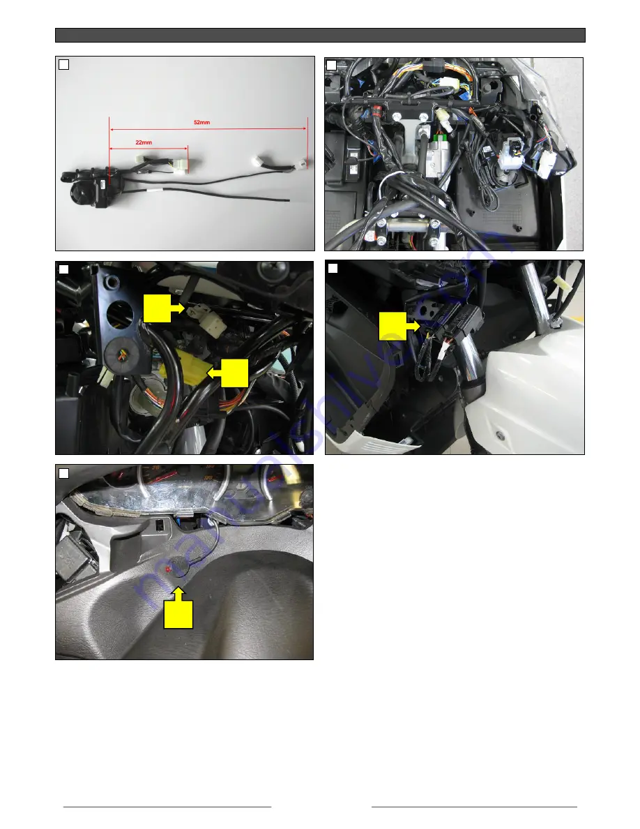
BURGMAN AN 400
H
7
9
6
8
E
F
G
10
Page 1: ...ations Burgman 125 UH125 K7 Burgman 200 UH200 K7 Burgman 400 AN400 K5 Burgman 650 AN650 K4 Temps d installation 30 45 min Descrizione Kit di installazione per sistema d allarme Numero di codice 990D0...
Page 2: ...and press them for a few seconds f Connect the 1 pin connector pict 3 A 12V to the plug play harness counterpart g Identify the 13 pin turn indicators connector yellow plug pict 3 B Interpose the plug...
Page 3: ...ect the negative battery pole k Check and test the system point 2 2 SYSTEM TEST a To arm the system push once BUTTON 1 of the remote control Arming is confirmed by 2 turn indicators alternated flashin...
Page 4: ...b 1 positionieren und einige Sekunden lang festdr cken f Den 1 Weg Stecker Abb 3 A 12V mit dem Plug Play Kabelende verbinden g Den 13 Wege Stecker der Fahrtrichtungsanzeiger ausfindig machen gelber St...
Page 5: ...ng des Alarmsystems die TASTE 1 auf der Fernbedienung dr cken Die Aktivierung wird best tigt durch Zweifaches Blinken der Fahrtrichtungsanzeiger rechts links rechts links Zwei akustische Signale Piept...
Page 6: ...t quelques secondes f Relier le connecteur 1 p le fig 3 A 12V la partie correspondante du c blage plug play g Identifier le connecteur 13 p les des indicateurs de direction connecteur jaune fig 3 B In...
Page 7: ...TEME a Appuyer la TOUCHE 1 de la t l commande pour activer le syst me d alarme L activation est confirm e par 2 clignotements altern s droit gauche droit gauche des indicateurs de direction 2 signalis...
Page 8: ...icato in fig 1 facendo pressione per alcuni secondi f Collegare il connettore a 1 via fig 3 A 12V con la controparte del cablaggio plug play g Individuare il connettore a 13 vie degli indicatori di di...
Page 9: ...o 2 2 COLLAUDO DEL SISTEMA a Premere il TASTO 1 del radiocomando per attivare il sistema di allarme L attivazione confermata da 2 lampeggi alternati destro sinistro destro sinistro degli indicatori di...
Page 10: ...o durante algunos segundos f Unir el conectador de 1 contacto im 3 A 12V con la contraparte del cableado plug play g Identificar el conectador de 13 contactos de los intermitentes conectador amarillo...
Page 11: ...istema punto 2 2 COMPROBACI N DEL SISTEMA a Apretar el BOT N 1 del mando para activar el sistema de alarma La activaci n se confirma con 2 relampagueos alternados de los intermitentes derecho izquierd...
Page 12: ...SUZUKI GENUINE ACCESSORIES 12 BURGMAN UH 125 200 A B C D 3 1 5 4 2...
Page 13: ...SUZUKI GENUINE ACCESSORIES 13 BURGMAN AN 400 H 7 9 6 8 E F G 10...
Page 14: ...SUZUKI GENUINE ACCESSORIES 14 BURGMAN AN 650 L 13 11 12 14 J I K Developed and manufactured by Sonar Electronic srl Italy I M 990D0 05H01 ALM rev00 20100608...