background image

    GS500K4/FK4 (’04-MODEL)     7

 CRAN BALANCER

Unit: mm (in)

OIL PUMP

ITEM

STANDARD

LIMIT

Piston ring groove width

1st

1.21 – 1.23

(0.047 – 0.048)

2nd

1.21 – 1.23

(0.047 – 0.048)

Oil

2.51 – 2.53

(0.099 – 0.100)

Piston ring thickness

1st

1.17 – 1.19

(0.046 – 0.047)

2nd

1.17 – 1.19

(0.046 – 0.047)

Piston pin bore

18.002 – 18.008

(0.7087 – 0.7090)

 18.030

 (0.7098)

Piston pin O.D.

17.995 – 18.000

(0.7085 – 0.7087)

 17.980

 (0.7079)

ITEM

STANDARD

 LIMIT

Conrod small end I.D.

18.006 – 18.014

(0.7089 – 0.7092)

18.040

(0.7102)

Conrod big end side clearance

0.1 – 0.2

(0.004 – 0.008)

0.3

(0.012)

Conrod big end width

22.95 – 23.00

(0.904 – 0.906)

Crank pin width

23.10 – 23.15

(0.909 – 0.911)

Conrod big end oil clearance

0.024 – 0.048

(0.0009 – 0.0019)

0.080

(0.0031)

Crank pin O.D.

33.976 – 34.000

(1.3376 – 1.3386)

Crankshaft journal oil clearance

0.020 – 0.044

(0.0008 – 0.0017)

0.080

(0.0031)

Crankshaft journal O.D.

31.976 – 32.000

(1.2589 – 1.2598)

Crankshaft thrust bearing
thickness

2.950 – 2.975

(0.1161 – 0.1171)

2.850

(0.1122)

Crankshaft runout

0.05

(0.002)

Balancer journal oil clearance

0.020 – 0.044

(0.0008 – 0.0017)

0.080

(0.0031)

Balancer journal O.D.

31.984 – 32.000

(1.2592 – 1.2598)

Balancer spring free length

14.9

(0.59)

ITEM

STANDARD

 LIMIT

Oil pump reduction ratio

1.879 (76/28 × 27/39)

Oil pressure (at 60 °C, 140 °F)

Above 200 kPa (2.0 kgf/cm

2

, 28 psi)

Below 500 kPa (5.0 kgf/cm

2

, 71 psi)

at 3 000 r/min

Summary of Contents for 2004 GS500

Page 1: ......

Page 2: ...man ual SPECIFICATIONS 3 SERVICE DATA 5 TIGHTENING TORQUE 13 ENGINE 13 CHASSIS 14 PERIODIC MAINTENANCE CHART 15 LOWER CRANKCASE 16 COWLING For GS500F 17 FRONT FORK 18 REMOVAL 18 DISASSEMBLY 19 INSPECTION 20 REASSEMBLY 21 INSTALLATION 23 WIRING DIAGRAM 24 GS500K4 UK4 P 02 09 19 54 24 GS500FK4 FUK4 P 02 19 54 24 GS500K4 P 24 28 25 GS500FK4 P 03 24 28 33 26 WIRING HARNESS AND HOSE ROUTING 27 WIRING H...

Page 3: ...NTRY AND AREA CODES The following codes stand for the applicable country ies and area s CODE COUNTRY or AREA P 02 P 03 P 09 P 19 P 24 P 28 P 33 P 54 UK USA Except for California Colombia EU Australia Canada California USA Spain ...

Page 4: ...r cooled DOHC Number of cylinders 2 Bore 74 0 mm 2 913 in Stroke 56 6 mm 2 228 in Displacement 487 cm3 29 7 cu in Compression ratio 9 0 1 Carburetor BSR34 twin Air cleaner Non woven fabric element Starter system Electric Lubrication system Wet sump Idle speed 1 200 100 r min DRIVE TRAIN Clutch Wet multi plate type Transmission 6 speed constant mesh Gearshift pattern 1 down 5 up Primary reduction r...

Page 5: ... 11 Ah 10 HR Generator Three phase A C generator Fuse 20 A Headlight 12 V 60 55 W Position light 12 V 4 W GS500 U 12 V 5 W GS500F FU Turn signal light 12 V 21 W Brake light Taillight 12 V 32 3 cp 2 pcs P 03 28 33 12 V 21 5 W 2 pcs Others Speedometer light 12 V 1 7 W Tachometer light 12 V 1 7 W Neutral indicator light 12 V 1 7 W High beam indicator light 12 V 1 7 W Turn signal indicator light 12 V ...

Page 6: ...lection IN EX 0 35 0 014 Valve guide I D IN EX 7 000 7 015 0 2756 0 2762 Valve stem O D IN 6 960 6 975 0 2740 0 2746 EX 6 945 6 960 0 2734 0 2740 Valve stem runout IN EX 0 05 0 002 Valve head thickness IN EX 0 5 0 02 Valve seat width IN EX 1 0 1 2 0 04 0 05 Valve head radial runout IN EX 0 03 0 001 Valve spring free length IN EX INNER 35 6 1 40 OUTER 40 6 1 60 Valve spring tension IN EX INNER 10 9...

Page 7: ... distortion 0 10 0 004 ITEM STANDARD LIMIT Compression pressure 1 000 1 400 kPa 10 14 kgf cm2 142 199 psi 800 kPa 8 kgf cm2 144 psi Compression pressure difference 200 kPa 2 kgf cm2 28 psi Piston to cylinder clearance 0 050 0 060 0 0020 0 0024 0 120 0 0047 Cylinder bore 74 000 74 015 2 9134 2 9140 74 080 2 9165 Piston diam 73 945 73 960 2 9112 2 9118 Measure at 15 mm 0 6 in from the skirt end 73 8...

Page 8: ...end width 22 95 23 00 0 904 0 906 Crank pin width 23 10 23 15 0 909 0 911 Conrod big end oil clearance 0 024 0 048 0 0009 0 0019 0 080 0 0031 Crank pin O D 33 976 34 000 1 3376 1 3386 Crankshaft journal oil clearance 0 020 0 044 0 0008 0 0017 0 080 0 0031 Crankshaft journal O D 31 976 32 000 1 2589 1 2598 Crankshaft thrust bearing thickness 2 950 2 975 0 1161 0 1171 2 850 0 1122 Crankshaft runout ...

Page 9: ...ngth 60 8 2 39 ITEM STANDARD LIMIT Primary reduction ratio 2 714 76 28 Final reduction ratio 2 437 39 16 Gear ratios Low 2 461 32 13 2nd 1 777 32 18 3rd 1 380 29 21 4th 1 125 27 24 5th 0 961 25 26 Top 0 851 23 27 Shift fork to groove clearance 0 1 0 3 0 004 0 012 0 5 0 020 Shift fork groove width No 1 No 2 No 3 5 5 5 6 0 217 0 220 Shift fork thickness No 1 No 2 No 3 5 3 5 4 0 209 0 213 Countershaf...

Page 10: ...3rd Needle jet N J P 5M Throttle valve Th V 105 Pilot jet P J 17 5 Pilot screw P S 3 turns back Throttle cable play 2 0 4 0 mm 0 08 0 16 in ITEM SPECIFICATION GS500 P 09 28 GS500F P 03 28 GS500F P 33 Carburetor type MIKUNI BSR34 Bore size 34 mm I D No 01DS 01DU Idle r min 1 200 100 r min Float height 13 0 1 0 mm Main jet M J Jet needle J N 5DH91 5DH60 Needle jet N J Throttle valve Th V 105 Pilot j...

Page 11: ...ary peak voltage 100 V and more Probe W or B Y Probe Ground Generator Max output Approx 200 W at 5 000 r min Generator no load voltage More than 75 V AC at 5 000 r min Regulated voltage 13 5 15 5 V at 5 000 r min Starter relay resistance 3 5 Ω Battery Type designation CB10L B2 Capacity 12 V 39 6 kC 11 Ah 10 HR Standard electrolyte S G 1 28 at 20 C 68 F Fuse size 20 A ITEM SPECIFICATION GS500 U P 0...

Page 12: ...iam Front 12 630 12 670 0 4972 0 4988 Rear 12 657 12 684 0 4983 0 4994 Brake caliper cylinder bore Front 30 230 30 306 1 1902 1 1931 Rear 38 180 38 256 1 5031 1 5061 Brake caliper piston diam Front 30 150 30 200 1 1870 1 1890 Rear 38 098 38 148 1 4999 1 5019 Wheel rim runout Axial 2 0 0 08 Radial 2 0 0 08 Wheel axle runout Front 0 25 0 010 Rear 0 25 0 010 Wheel rim size Front 17 MT3 00 17M C MT3 0...

Page 13: ...225 2 25 33 REAR 250 2 50 36 280 2 80 41 ITEM SPECIFICATION NOTE Fuel type Use only unleaded gasoline of at least 87 pump octane R 2 M 2 or 91 octane or higher rated by the research method Gasoline containing MTBE Methyl Tertiary Butyl Ether less than 10 ethanol or less than 5 methanol with appropriate cosolvents and corro sion inhibitor is permissible P 03 28 33 Gasoline used should be graded 91 ...

Page 14: ...Generator mounting rotor bolt 120 12 0 87 0 Starter clutch bolt 18 1 8 13 0 Signal generator bolt 20 2 0 14 5 Crankcase bolt 6 mm 11 1 1 8 0 8 mm 22 2 2 16 0 Counter balancer shaft setting bolt 40 4 0 29 0 Oil pump mounting screw 10 1 0 7 0 Oil pressure regulator 19 1 9 13 5 Oil drain plug 23 2 3 16 5 Oil pan bolt 14 1 4 10 0 Clutch sleeve hub nut 50 5 0 36 0 Clutch spring set bolt 5 0 5 3 5 Oil c...

Page 15: ...mounting bolt 43 4 3 31 0 Front footrest bolt 23 2 3 16 5 Brake hose union bolt 23 2 3 16 5 Air bleeder valve 8 0 8 6 0 Front and rear disc bolt 23 2 3 16 5 Swingarm pivot nut 72 7 2 52 0 Rear shock absorber upper and lower mounting nut 60 6 0 43 5 Rear cusion lever rod mounting nut 85 8 5 61 5 Rear cusion lever mounting nut Front Center 85 8 5 61 5 Rear brake caliper mounting bolt 26 2 6 19 0 Rea...

Page 16: ...3 000 km 2 000 miles and replace every 12 000 km 7 500 miles Exhaust pipe bolts and muffler bolts T T T T T Tappet clearance I I I I I Spark plugs I R I R Fuel line I I I I I Replace every 4 years Engine oil and filter R R R R R Idle speed I I I I I Throttle cable play I I I I I Throttle valve synchronization I I I C A only Evaporative emission system California model only I I Replace vapor hose e...

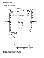
Page 17: ...ASE 99104 31140 SUZUKI BOND 1207B USA 99000 31110 SUZUKI BOND 1215 Others Apply SUZUKI BOND to the mating surface of the lower and upper crankcase at shaded area Dowel pin position Dowel pin position Dowel pin position Dowel pin position ...

Page 18: ...GS500K4 FK4 04 MODEL 17 COWLING For GS500F 1 Screen 2 Front cowling cover Center 3 Front cowling 4 Front cowling cover LH 5 Front cowling cover RH 6 Cowling brace ...

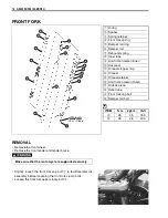
Page 19: ...fork upper clamp bolt 2 1 O ring 2 Spacer 3 Spring retainer 4 Front fork spring 5 Damper rod ring 6 Damper rod 7 Rebound spring 8 Inner tube 9 Anti friction metal Inner 0 Dust seal A Oil seal stopper ring B Oil seal C Oil seal retainer D Anti friction metal Outer E Oil lock piece F Outer tube A Front fork cap bolt B Damper rod bolt ITEM N m kgf m lb ft A 25 2 5 18 0 B 28 2 8 20 0 USA Others Make s...

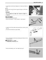
Page 20: ...rk cap bolt Remove the spacer 1 spring retainer 2 and spring 3 Invert the front fork and stroke it several times to drain out the fork oil Hold the fork inverted for a few minutes Remove the damper rod bolt using the special tools and 7 mm hexagon wrench 09940 34520 T handle 09940 34531 Attachment A Remove the damper rod 4 and rebound spring 5 Do not operate the brake lever while the caliper is re...

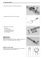
Page 21: ... B Oil seal retainer C Anti friction metal Outer D Anti friction metal Inner E Oil lock piece INSPECTION DAMPER ROD RING Inspect the damper rod ring for wear or damage If damper rod ring is worn or damaged replace it with a new one INNER AND OUTER TUBES Inspect the inner and outer tube sliding surfaces for scratches or damage Replace the tube s if necessary ...

Page 22: ...ls for wear and damage Replace the metal s if necessary REASSEMBLY Reassembly is in the reverse order of disassembly Pay atten tion to the following points ANTI FRICTION METALS Clean the inner tube metal groove Hold the inner tube vertically and install the anti friction metals by hand OIL SEAL Apply fork oil lightly to the lip of a new oil seal and install it 99000 99044 10G SUZUKI FORK OIL 10 or...

Page 23: ...eal DAMPER ROD Install a new gasket 1 Apply THREAD LOCK to the damper rod bolt and tighten it to the specified torque 99000 32050 THREAD LOCK 1342 USA 99000 32110 THREAD LOCK 1322 Others Damper rod bolt 28 N m 2 8 kgf m 20 0 lb ft 09940 34520 T handle 09940 34531 Attachment A FORK OIL Pour specified fork oil into the inner tube Front fork oil capacity each leg 380 ml 12 8 13 4 US Imp oz 99000 9904...

Page 24: ...the front fork assembly align the upper sur face A of the inner tube with the surface B of the steering upper bracket Tighten the front fork upper clamp bolt 1 to the specified torque Front fork upper clamp bolt 23 N m 2 3 kgf m 16 5 lb ft Tighten the front fork lower clamp bolt 2 to the specified torque Front fork lower clamp bolt 30 N m 3 0 kgf m 21 5 lb ft Tighten the front fork cap bolt to the...

Page 25: ...B R Lg B W Lg B W B B W B B W W B B W Br Lg B W Lg B W Br B W Br B W Y B W W B B W B B W B Bl B Bl B Bl G G O O O Bl G B W G B W Br B Bl G Y B B B B B B W Y G R Y Y Y Y Y Y R B W B W B W R B W Br B Bl G Y G Bl R B Bl G Bl R B Bl B Bl B W Lg Lbl B O W Y O B Y Y G B Bl B W Lg Lbl B O R W Y Y W B Y B Y O G Y Bl B B W Lg B Y B W O O B R O G Y Bl B B W Lg B Y B W O Gr R O O Br R O Gr Br O Bl O W O W B ...

Page 26: ... B W Br Lg B W Lg B W B B Br B W Y B W W B B W B B W B Bl B Bl B Bl G G O O O Bl G B W G B W Br B Bl G Y B W Y G R Y Y Y Y Y Y R B W B W B W R B W Br B Bl G Y G Bl R B Bl G Bl R B Bl B Bl B W Lg Lbl B O W Y O B Y Y G B Bl B W Lg Lbl B O R W Y Y W B Y B Y O G Y Bl B B W Lg B Y B W O O B R O G Y Bl B B W Lg B Y B W O Gr R O O Br R O Gr Br O Bl O W O W B B Y O W B O W W O Lbl O B O W B R B Bl Y G B Y...

Page 27: ... Bl R G Bl O W B R Lg B W Lg B W B B W B B W W B B W Br Lg B W Lg B W Y B W W B B W B B W B Bl B Bl B Bl G G O O O Bl G B W G B W Br B Bl G Y B W Y G R Y Y Y Y Y Y R B W B W B W R B W Br B Bl G Y G Bl R B Bl G Bl R B Bl B Bl B W Lg Lbl B O W Y O B Y Y G B Bl B W Lg Lbl B O R W Y Y W B Y B Y O G Y Bl B B W Lg B Y B W O O B R O G Y Bl B B W Lg B Y B W O Gr R O O Br R O Gr Br R O Gr R O Gr O Bl O W O...

Page 28: ...coil RH Spark plug cap Ignition coil lead wire Clutch cable Throttle cable Wiring harness Neutral switch Regulator Pass the regulator lead wire under the wiring harness Clamp the wiring harness at blue tape on the wiring harness Regulator Side stand relay Turn signal relay Side stand switch coupler must be located over the starter relay coupler Rear brake light switch Solenoid TPS A B Pass the com...

Page 29: ...dlebar switch Right handlebar switch Clamp Left turn signal Right turn signal Wiring harness VIEW A previous page Frame Clamp Clamp Clamp Signal generator Battery lead wire Generator Battery lead wire Turn signal lead wire Rear fender Generator lead wire Signal generator lead wire Pass the turn signal light lead wire between the frame and rear fender No slack Pass the lead wires inside of all drai...

Page 30: ...itch R Speedometer Ignition coil L Clamp Handlebar switch L Ignition switch Horn Front turn signal light L Clamp Clamp Wiring harness To the front turn signal light R Starter cable Handlebar switch L lead wire Clamp Handlebar switch L Ignition switch Starter cable Clutch cable Front turn signal light lead wire L Clamp Horn Clutch cable Clamp Wiring harness Throttle cable Starater cable Clutch cabl...

Page 31: ...30 GS500K4 FK4 04 MODEL OIL COOLER HOSE ROUTING For GS500F 1 Oil cooler 2 Oil cooler hose LH 3 Oil cooler hose RH 26 N m 2 6 kgf m 19 0 lb ft ...

Page 32: ... vent hose To the fuel valve Throttle cable Breather hose Air cleaner Air cleaner drain hose Air control hose Throttle cable Fuel valve vacuum hose Carburetor clamp position Intake manifold side Carburetor clamp position Air cleaner side LH LH RH RH 15 Air vent hose Breather hose ...

Page 33: ...en Marking Red PAIR valve vacuum hose Fuel valve vacuum hose No 2 Connect the thick side of the vacuum hose to the 3 way joint PAIR air cleaner hose Marking Yellow PAIR valve PAIR valve vacuum hose Fuel valve vacuum hose No 1 3 way joint Keep clearance between the hose clips and the frame ...

Page 34: ...E ROUTING For GS500F Throttle cable Front brake hose Clamp Front brake caliper Stopper After positioning the brake hose union to the stopper tighten the union bolt 28 28 10 Throttle cable Clamp 14 Front brake hose 23 N m 2 3 kgf m 16 5 lb ft ...

Page 35: ...34 GS500K4 FK4 04 MODEL FRONT TURN SIGNAL LIGHT INSTALLATION For GS500F 1 Forward 2 Cowling 3 Front turn signal light 14 N m 1 4 kgf m 10 0 lb ft ...

Page 36: ...Prepared by January 2004 Part No 99501 34150 03E Printed in Japan 36 ...

Page 37: ......

Reviews: