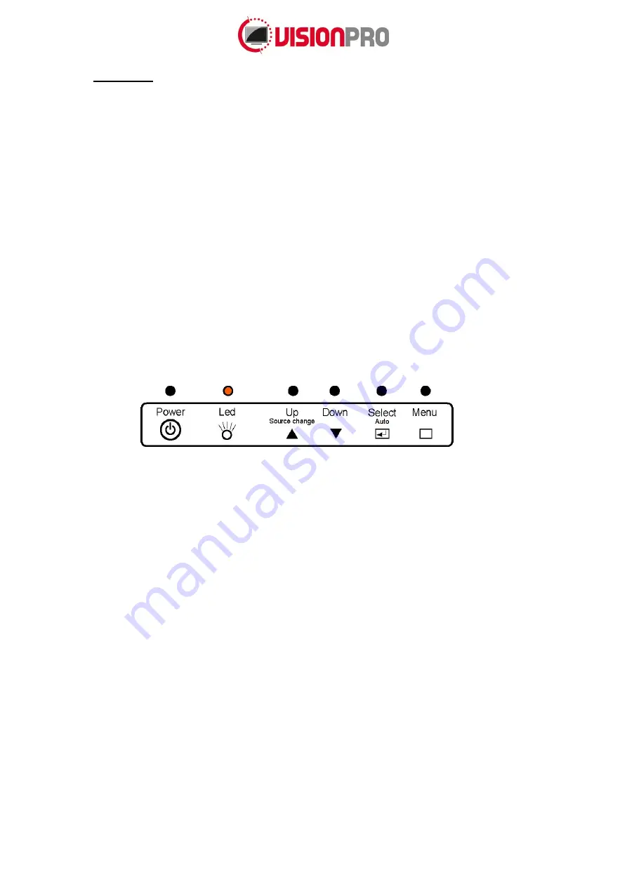
background image


Page 5 of 


6. 

Operation 

 
Color LED: 

This LED shows the state of the controller.  


Green is the 

“normal state”. 


Red is the “Off mode”. (Can’t find Sync. signals)  


Amber is the 

“DPMS mode” (

Display Power Management Signaling). 

PC Settings: 

The PC needs to be set to an appropriate graphics mode that has the same resolution 

as the LCD panel to have clear screen image. The vertical refresh rate should be set to one of 
56~75Hz, non-interlaced signal. 

LCD display System Settings: 

The OSD (On Screen Display) provides certain functions to have 

clear image and others. This board supports 5 buttons OSD operation as a standard. The control 
functions defined on OSD operation are as below. 

PC Graphics Output: 

Signal quality is very important. If there is noise or instability in the PC graphics 

output, it may result in visible noise on the display. Refer to the graphic modes table in specification 
section for supported modes. Non-interlaced & interlaced video input is acceptable. 

(If installed) USB cable:

 Plug the USB cable to the connector on the backside of the monitor.


VGA cable: 

Plug the VGA cable to the connector on the backside of the monitor. 

DVI-D Cable:

 Plug the DVI-D Cable (not included) to the connector on the backside of the monitor. 

Power supply: 

Plug the 12V power supply (not included) to the connector on the backside of the 

monitor (separate power supply 182-0520). 

Power on: 

Switch on the monitor by using the on/off switch on the OSD control buttons. 

PC Setting: 

The controller has been designed to take a very wide range of input signals. However, to


optimize the PC’s graphic performance, we recommend choosing 60Hz vertical refresh rate. This will 
not cause screen flicker. 


The chosen OSD settings will be stored in memory. The OSD menu can be cleared from the screen by 
moving the selection bar to the EXIT MENU icon pressing the SEL button. The OSD menu will  
automatically be cleared from the screen after a few second of non-use. 


Summary of Contents for Vision Pro 150TFT 2154 Series

Page 1: ...itor Model 150TFT X 2154 Manual Version 1 0 December 2015 Antonie van Leeuwenhoekstraat 9 3261 LT Oud Beijerland The Netherlands Phone 31 0 186 643333 Fax 31 0 186 643322 Email info suzohapp nl Web eu suzohapp com ...

Page 2: ...Page 2 of 9 Index 1 Introduction 3 2 Safety 3 3 Model descriptions 3 4 Monitor connection 3 5 Monitor specifications 4 6 Operation 5 7 OSD MENU 6 8 Mounting instructions 8 Accessories 9 9 ...

Page 3: ...ntilation slots It is important that your monitor remains dry Do not pour liquid into or onto the monitor If the monitor becomes wet do not attempt to repair it yourself If the liquid crystal materials leaks from the panel it should be kept away from the eyes or mouth In case of contact with hands legs or clothes it must be washed away thoroughly with soap Warning This is a class A product In a do...

Page 4: ... Mode V Frequency Hz 50 60 75 Depends on Mode DVI D Input DATA CLK VPP 450 500 900 Differential Display Characteristics Item Unit Specifications Screen Diagonal inch 21 5 Active Area mm 476 064 H x 267 786 V Pixels 1920 x 1080 RoHS Compliance RoHS Compliance Optical Characteristics Item Unit Conditions Min Typ Max Remarks Surface Luminance white cd m2 200 250 Contrast Ratio C R 700 1000 Response T...

Page 5: ...n specification section for supported modes Non interlaced interlaced video input is acceptable If installed USB cable Plug the USB cable to the connector on the backside of the monitor VGA cable Plug the VGA cable to the connector on the backside of the monitor DVI D Cable Plug the DVI D Cable not included to the connector on the backside of the monitor Power supply Plug the 12V power supply not ...

Page 6: ...Page 6 of 9 7 OSD MENU PICTURE COLOR SCREEN OSD SETUP ...

Page 7: ...d 50 0 100 PC ONLY Green 50 0 100 Blue 50 0 100 Auto Color To Start Screen Auto Configure To Start H Position 50 0 100 PC ONLY V Position 50 0 100 Clock 50 0 100 Phase 30 0 100 OSD Language English English Deutsch Francais Italiano Espanol Korean H Position 50 0 100 V Position 50 0 100 Transparency 33 0 100 OSD Time 10 3 30 SETUP Source RGB DVI AUTO Factory reset To Start Aspect Off On Off ...

Page 8: ...Page 8 of 9 9 Mounting instructions 204 0 512 6 MOUNT TO MOUNT 204 0 307 6 MOUNT TO MOUNT 33 3 USER MOUNT M4 2X EACH SIDE VGA DISPLAYPORT 12VDC 14 3 14 3 OSD BUTTONS VESA MOUNT 100 X 100 M4 ...

Page 9: ...Page 9 of 9 10 Accessories Part number Description 150 0049 Power supply input 100 240V output 12V 5A 22 0012 4 Power cable Euro lead 1 80M 149 0112 11 VGA cable 1 80m 149 0121 DVI D Cable 2 mtr 18 1 ...

Reviews: