background image


1- SAFETY 

1.1-  DANGER, WARNING AND CAUTION 

The words 

DANGER

WARNING

 and 

CAUTION

 are used to 

identify the levels of seriousness of certain hazards. It is 
important that you understand their meaning. You will notice 
these words in the manual as follows: 


DANGER 

Immediate  hazards  which  WILL  result  in  death  or  serious 
bodily and/or material damage.


WARNING 


Hazards or unsafe practices which CAN result in death or 

serious bodily and /or material damage. 


CAUTION 


Hazards or unsafe practices which CAN result in minor 

bodily and /or material damage. 

1.2-  IMPORTANT INFORMATION 

WARNING 


Non-observance  of  the  safety  regulations  outlined  in  this 
manual  will  potentially  lead  to  consequences  resulting  in 
death, serious bodily injury and/or property damage. 


WARNING 


Installation and  repairs  performed  by  unqualified  persons 
can  result  in  hazards  to  them  and  to  others.  Installations 
must  conform  to  local  codes  or,  in  the  absence  of  such 
codes, to codes of the country having jurisdiction. 


The  information  contained  in  this  manual  is  intended  for 
use  by  a  qualified  technician,  familiar  with  safety 
procedures and who is equipped with the proper tools and 
test instruments. 


Failure  to carefully  read  and  follow all  instructions  in  this 
manual  can  result  in  death,  bodily  injury  and/or  property 
damage. 


a.  It  is  the  homeowner’s  responsibility  to  engage  a 

qualified technician for the installation and subsequent 
servicing of this furnace; 

b.  Do not use this furnace if any part of it was under water.  

Call  a  qualified  service  technician  immediately  to 
assess the damage and to replace all critical parts that 
were in contact with water; 

c.  Do  not  store  gasoline  or  any  other  flammable 

substances, such as paper or carton near the furnace; 

d.  Never  block  or  otherwise  obstruct  the  filter  and/or 

return air openings; 

e.  Ask the technician installing your furnace to show and 

explain to you the following items: 

i.  The main disconnect switch or circuit breaker; 

ii.  The air filter and how to change it (check monthly 

and clean or replace if necessary); 

f. 

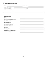
Before  calling  for  service,  be  sure  to  have  the 
information  of  section  5


of  your  manual  close  by  in 

order  to  be  able  to  provide  the  contractor  with  the 
required  information,  such  as  the  model  and  serial 
numbers of the furnace. 


IMPORTANT:


All  local  and  national  code  requirements 

governing the installation of central electric heating equipment, 
wiring and the flue connection MUST be followed.  Some of the 
codes that may apply are: 

ANSI/NFPA 70: 

National Electrical Code 

CSA C22.1 

or

 CSA C22.10: 

Canadian Electrical Code


Only the latest issues of these codes may be used, and are 
available from either: 


The National Fire Protection Agency 


1 Batterymarch Park 


Quincy, MA 02269 

or 


The Canadian Standards Association 


178 Rexdale Blvd. 

Rexdale, Ontario M9W 1R3 


1.3-  DANGER OF FREEZING 

CAUTION 


If  your  furnace  is  shut  down  during  the  cold  weather 
season,  water  pipes  may  freeze,  burst  and  cause  serious 
water  damage.    Turn  off  the  water  supply  and  bleed  the 
pipes. 


If the heater is left unattended during the cold weather season, 
take the following precautions: 

a.  Close  the  main  water  valve  in  the  house  and  purge  the 

pipes if possible.  Open all the faucets in the house; 

b.  Ask someone to frequently check the house during the cold 

weather season to make sure that there is sufficient heat to 
prevent the pipes from freezing.  Tell this person to call an 
emergency number if required. 
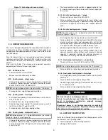
2- INSTALLATION 

This furnace is a true multi-position unit, in that it will function in 
an upflow, downflow or horizontal configuration to the left or the 
right.  Only a few modifications are required during installation 
to change from one position to another.  The unit is shipped in 
the upflow configuration and instructions as to how to change to 
the other positions are included in this manual. 

Summary of Contents for SUP10-A240V12

Page 1: ...ial Boulevard Sherbrooke Quebec Canada J1L 1V8 Caution Do not tamper with the unit or its controls Call a qualified service technician INSTALLER SERVICE TECHNICIAN USE THE INFORMATION IN THIS MANUAL F...

Page 2: ...ng mode dehumidification 9 3 3 5 Electric heat heating mode 1 stage 9 3 3 6 Electric heat heating mode 2 stage 9 3 3 7 Heat pump heating mode single stage 9 3 3 8 Heat pump heating mode two stage 9 3...

Page 3: ...e Ask the technician installing your furnace to show and explain to you the following items i The main disconnect switch or circuit breaker ii The air filter and how to change it check monthly and cl...

Page 4: ...nstallation The return duct may be installed to the back to the bottom on the left side or on the right side of the unit The supply duct shall be installed on the top of the unit Care should be taken...

Page 5: ...installation must be performed with copper wire ONLY in order to comply with the Canadian electrical code The usage of an aluminum or copper wire is acceptable on models 25kW and lower Move all wires...

Page 6: ...er the vertical sections of the supply and return air duct with soundproofing material c Use baffles in short radius elbows d Use flexible hangers to suspend the ducts The SUPREME furnace is equipped...

Page 7: ...irflow and zero 0 ON delay programmed into the ECM motor that cannot be overridden Four 4 motor operation delay profiles are provided to customize and enhance system operation Refer to Figure 10 and F...

Page 8: ...heat pump When using a heat pump a thermostat with dial fuel option or a fossil fuel kit is required that prevents the operation of the electric elements and the heat pump at the same time Refer to t...

Page 9: ...ng mode 1 stage Thermostat closes circuit R to W1 or W2 Furnace delivers the selected electric heat airflow and maximum heating capacity is powered starting the heating elements in sequence with a del...

Page 10: ...igned to engage during the improper functioning of the blower or when the filter was improperly maintained 3 4 2 High limit verification After operating the furnace for at least 15 minutes restrict th...

Page 11: ...ler name and address START UP RESULTS Voltage Total current consumed by the elements Supply air temperature Return air temperature Supply air duct static pressure Return air duct static pressure Total...

Page 12: ...N Fan ON after delays at selected Cooling CFM OFF Compressor OFF Fan OFF after selected cooling delays ON Compressor ON Fan ON after delays at 80 of the selected Cooling CFM OFF Compressor OFF Fan OFF...

Page 13: ...2 6 0 5 2 6 0 5 2 6 0 5 2 6 0 5 2 6 0 Heating Elements Consumption 240V 208V Amp 41 4 35 9 62 1 53 8 75 8 65 7 82 8 71 8 96 5 83 6 103 5 89 7 82 8 71 8 96 5 83 6 103 5 89 7 113 6 98 5 124 3 107 7 Tota...

Page 14: ...Adjustment WHITE wire position ON Delay Time OFF Delay CFM Time 0 90 0 sec 100 90 sec 30 90 30 sec 100 90 sec 0 0 0 sec 0 sec ENH 30 sec 70 150 sec No adjustment required ON Delay Time OFF Delay CFM...

Page 15: ...575 1150 ON OFF DELAY Adjustment WHITE wire position ON Delay Time OFF Delay CFM Time 0 90 0 sec 100 90 sec 30 90 30 sec 100 90 sec 0 0 0 sec 0 sec ENH 30 sec 70 150 sec No adjustment required ON Del...

Page 16: ...16 Figure 15 Furnace dimensions...

Page 17: ...17 Figure 16 Electrical diagram SUPREME Advantage ECM...

Page 18: ...18 Figure 17 Parts list SUPREME Advantage ECM...

Page 19: ...3 25kw 26 B04282 Electrical sequencer kit Supreme 18 20kw 27 B04283 Electrical sequencer kit Supreme 15kw 28 B04284 Electrical sequencer kit Supreme 10kw 29 B04275 Plastic top door 30 X50042 Label log...

Reviews: