


15
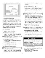
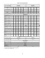
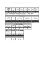
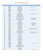
Table 4: Electric furnace SUP, ECM 1.0 HP motor, air flow tables
AC / HP SIZE
Adjustment
BLUE wire position
A/C size
(TONS)
CFM ?
AC/HP CFM ADJUST
BLACK wire position = (NOM)
CFM ?
AC/HP CFM ADJUST
BLACK wire position = (LO)
CFM ?
AC/HP CFM ADJUST
BLACK wire position = (HI)
60
5,0
2000
1800
2200
48
4,0
1600
1440
1760
42
3,5
1400
1260
1540
36
3,0
1200
1080
1320
AC / HP SIZE
Selection
BLUE wire position
A/C size
(TONS)
CFM ?
CONTINUOUS FAN
YELLOW wire position = (LO)
CFM ?
CONTINUOUS FAN
YELLOW wire position = (MED)
CFM ?
CONTINUOUS FAN
YELLOW wire position = (HI)
60
5,0
1000
1600
2000
48
4,0
800
1280
1600
42
3,5
700
1120
1400
36
3,0
600
960
1200
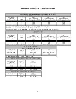
HEAT KW/CFM
adjustment
RED wire position
POWER
(Kw)
CFM
First stage
24 VAC on W1*
CFM
Second stage
24 VAC on W1 and/or W2*
27
27
700
1400
23
23
575
1150
ON / OFF DELAY
Adjustment
WHITE wire position
ON-Delay
Time
OFF-Delay
% CFM - Time
0 / 90
0 sec.
100% - 90 sec.
30 / 90
30 sec.
100% - 90 sec.
0 / 0
0 sec.
0 sec.
ENH
30 sec.
70 % - 150 sec.
No adjustment
required
ON-Delay
Time
OFF-Delay
% CFM - Time
-
0 sec.
50% - 60 sec.
ELECTRIC HEATING MODE
24 VAC (R) input on W1 and/or W2 only
* Remove the Jumper
J2
when a 2 stages thermostat is used
ON & OFF DELAY FOR COOLING AND HEAT PUMP HEATING MODE
DELAY PROFILE FOR ELECTRIC HEATING MODE
COOLING OR HEAT PUMP HEATING MODE (WITH HP-EFF SELECTED ? )
24 VAC (R) input on G, Y/Y2 and O (for cooling)
? In Cooling - Dehumidification mode, with no 24 VAC input to DH, the CFMs are reduced by 15%.
? The CFMs shown are reduced by 20% if there is 24 VAC input to Y1 only
? SYSTEM TYPE select to HP-EFF corresponds to 400 CFM/TONS - HP-COMFORT corresponds to 350 CFM/TONS
CONTINUOUS FAN
24 VAC (R) input on G only
? CFM's when AC/HP CFM ADJUST at NOM position. CFM's 10% lower or higher if AC/HP CFM ADJUST at LO or HI position.


