4
2.1
POSITIONING THE FURNACE
WARNING
Fire and explosion hazard.
The furnace must be installed in a level position, never
where it will slope toward the front.
Do not store or use gasoline or any other flammable
substances near the furnace
Non-observance of these instructions will potentially result
in death, bodily injury and/or property damage.
CAUTION
This furnace is not watertight and is not designed for
outdoor installation. It must be installed in such a manner
as to protect its electrical components from water.
Outdoor installation will lead to a hazardous electrical
condition and to premature failure of the equipment
If the furnace is installed in a basement or on a dirt floor, in a
crawl space for example, it is recommended to install the unit on
a cement base 2.5 cm to 5.0 cm (1’’ to 2’’) thick.
The unit must be installed in an area where the ambient and
return air temperatures are above 15˚C (60˚F). In addition, the
heater should also be located close to the center of the air
distribution system.
2.2 CLEARANCES TO COMBUSTIBLE
MATERIAL
2.2.1. Heating
unit
The furnace is approved for zero clearance to combustible
material regardless of the heating capacity.
2.2.2.
Supply air ducts
Ducts for furnaces with a heating capacity up to and including
20 k W, can be installed with a zero clearance to combustible
material.
Ducts for furnaces of 23 kW or more must have a clearance of
25 mm (1’’) to combustible material for the first 0.9 m (36’’) of
duct. Thereafter the clearance can be zero.
Units of 23 kW and up, installed in the downflow position must
use a DFB-FEM downflow base, which is especially designed
for this purpose. It ensures that the required clearances are
being adhered to.
2.3 CONFIGURATIONS
2.3.1. Upflow
installation
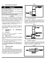
The return air opening may be located on either side of the
furnace. Care should be taken not to damage the wires inside,
while cutting the opening. Install the filter rack supplied with the
unit according to the instructions provided with it. It is also
recommended to install the blower door before handling or
moving the unit. Refer to Figure 1 for additional details.
Figure 1
2.3.2. Downflow
installation
When the furnace is installed in the downflow position on a
combustible floor, the clearances from combustibles must be
adhered to. The downflow base DFB-FEM can be used to
ensure these clearances. Refer to Figure 2 and the installation
instructions provided with the base.
Figure 2
2.3.3. Horizontal
installation
When the furnace is installed in the horizontal position, either
suspended or on a combustible floor with a choice of right or left
discharge, the clearances from combustible material must be
adhered to. Refer to Figure 3 for additional details.
Figure 3
Summary of Contents for FEM15-E230V1M-A
Page 12: ...12 FIGURE 9 Diagramme électrique ...
Page 17: ...17 COMPOSANTES ET PIÈCES DE REMPLACEMENT ...
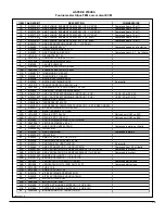
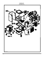
Page 18: ...18 LISTE DE PIÈCES Vue explosée B50081 Rev B ...
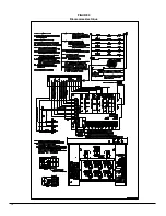
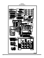
Page 31: ...12 FIGURE 9 Electrical Diagram ...
Page 36: ...17 COMPONENTS AND REPLACEMENT PARTS ...

