In case of Contrast
※
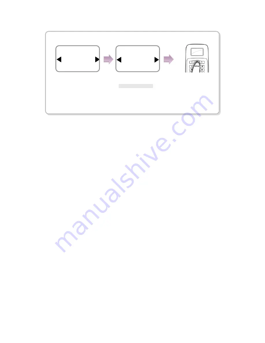
Contrast value is not affected by Factory default.
Use
▶
/
◀
buttons to
select
Contrast
and
press
OK
.
adjust contrast parameter.
* Default value is 18
Press
Item
System
18
Page 1: ...EN 102 00 BLS V1 13...
Page 2: ...ion purpose only All information included herein is subject to change without notice Suprema is not responsible for any changes direct or indirect arising from or related to us of this manual Copyrigh...
Page 3: ...ling a user 16 2 2 Editing a user data 18 2 3 Deleting a user data 21 3 Configuration for Screen and Sound 22 3 1 Date Time 22 3 2 Backlight 23 3 3 Sound 23 4 Device Configuration 24 4 1 Authorization...
Page 4: ...ndividuals Frequent change of password is recommended Any illegal access to your product may happen Do not operate the product with wet hands and keep the device away from any liquid contact It may ca...
Page 5: ...all mounting bracket Extended bracket Option Fixing Screws 2 EA Knife Blocks 2 EA Star shape wrench For fixing bracket Adapter Option Shrinkable Tubes The components shown above may differ depending o...
Page 6: ...rization success Red Sound beep beep beep Authorization failure Pink Sound beep Processing Blue and Sky Blue blink in turn at an interval of 2 seconds No sound Normal operation Red and Pink blink in t...
Page 7: ...ser in preparation of any abnormal situation like having a wounded finger or carrying an object with a hand In the case of a low recognition the user can register the same fingerprint twice to increas...
Page 8: ...initial administrator for setting devices See 1 4 1 Step 2 Configure the system Stand alone configuration see 1 4 2 or Secure I O configuration see 1 4 3 Step 3 Test for system operation Check the do...
Page 9: ...horization mode window appears use buttons to move to PIN Only and press OK 3 When the password entry window appears enter the desired password and press OK 4 When the password re entry window appears...
Page 10: ...ure above Use buttons to select Internal and press OK Use buttons to select Input 0 and press OK Relay Internal Door Exit Button Input 0 Internal Use buttons to select N O and press OK N O N C Type N...
Page 11: ...Internal Held Open Alarm Not Use Door Use buttons to select N O and press OK N O N C Use buttons to select Input 1 and press OK Not Use Input0 Input1 Use buttons to select Temporary Open for opening...
Page 12: ...Use buttons to select SIO Relay 0 and press OK Not Use SIO Input 0 SIO Input 1 Relay SIO Relay 0 Door Exit Button SIO Input 0 SIO Relay 0 Use buttons to select N O and press OK Type N O Exit Button D...
Page 13: ...Opening Mode Temporary Open Door Use buttons to select Temporary Open for opening mode and press OK Temporary Open Toggle Type N O Door Sensor Open Time sec 3 Door Use buttons to select Not Use for Fo...
Page 14: ...de selection in 4 1 Authorization 1 5 Authorization methods Finger Only Finger or PIN Enter the ID of the user and press OK Enter the password of the user and press OK The door is open with the authen...
Page 15: ...of the user and press OK The door is open with the authentication success message Enter ID 2 Enter Finger Enter PIN Access Granted ID 2 Enter ID 2 Enter the ID of the user and press OK Enter the pass...
Page 16: ...or enter another ID and press OK 1 8 digit number 4 Use buttons to select Level and press OK Level General Administrator The user enrollment and environment configuration are enabled only in Administr...
Page 17: ...for passing the door PIN Only Finger and PIN For password it is recommended to enter 4 to 8 digit number not to be easily exposed 7 When the user enrollment is successfully done the completion messag...
Page 18: ...and press OK 4 Use buttons to select the desired item and press OK Select any of Level Operation Mode Security Level Fingerprint PIN and Access Timezone Changing the user level The user registration...
Page 19: ...gerprint of the user Item Operation Mode Edit Use buttons to select Operation Mode and press OK Use buttons to select a operation mode and press OK Press OK Use buttons to select Security Level and pr...
Page 20: ...e zone of the user Select Weekday Sunday Per Weekday After selecting the timezone for each day as shown in the figure enter values for Start Time and End Time Item PIN Edit Use buttons to select PIN a...
Page 21: ...ress OK 3 After entering the ID or finger to delete and press OK 4 When the action is successfully made the message Deletion appears The deleted user cannot be recovered If necessary enroll it again U...
Page 22: ...a for Select Weekday or log data 1 Use buttons to select the Screen Sound icon and press OK 2 Use buttons to select the Date Time icon and press OK 3 Enter the current date by following the suggested...
Page 23: ...a backlight operation status and press OK 3 3 Sound 1 Use buttons to select the Screen Sound icon and press OK 2 Use buttons to select Sound icon and press OK 3 Use buttons to select the sound operat...
Page 24: ...lect Access Timezone and press OK Select the desired access time zone Always Allowed Always Blocked Per Weekday Authorization Item Access Timezone Authorization Device Type Always Allowed Access Timez...
Page 25: ...ion Use buttons to select Fingerprint and press OK Use buttons to select Security Level and press OK Use buttons to select Security Level and press OK Normal Secure More Secure Use buttons to select I...
Page 26: ...ttons to select any of Serial Conn Tamper On and Door and press OK In case of Serial Conn Serial Conn Speed Not Use 9600 19200 36400 57600 115200 It is used only when the log data is retrieved after c...
Page 27: ...ect Door Use buttons to select Internal Use buttons to select Exit Button Not Use Input 0 Input 1 Tamper Ignore In Out Relay Internal Door Exit Button Input 0 Internal Use buttons to select the type f...
Page 28: ...ttons to select the type of the exit button N O N C Type N O Exit Button Enter the held open time by using the Numeric buttons and press OK Forced Open Alarm Not Use Door Completed Use buttons to sele...
Page 29: ...Use buttons to select the alarm type Not Use Sound Backlight Sound and Light SIO Relay0 SIO Relay1 Held Open Alarm Sound Door Enter the time for Held Open Alarm by using the Numeric buttons and press...
Page 30: ...o select any of All and Select ID Use buttons to select any of All and Specify Date The log filtering result appears on the screen Use buttons to see the previous next logs 6 18 14 20 3 Delete OK 6 18...
Page 31: ...Use buttons to select Factory Default and press OK Use buttons to determine whether or not to initialize it Cancel Initialize Item Num Of User Information Item Firmware Ver Information User Templates...
Page 32: ...ema for details Item Delete User DB System In case of Delete the message Deletion appears Use buttons to select Delete All Log and press OK Use buttons to determine whether or not to delete them Cance...
Page 33: ...Contrast Contrast value is not affected by Factory default Use buttons to select Contrast and press OK Use buttons to adjust contrast parameter Default value is 18 Press OK Item Contrast System Item...
Page 34: ...Authorized The fingerprint authentication for the administrator fails when entering the menu Wrong PIN The entered password for authentication is not matched the enrolled one ID In Use The user ID to...
Page 35: ...gnition rate may vary due to the characteristic of each finger so enroll the fingerprint of another finger It was good at recognizing fingerprints but suddenly it fails in recognition Check whether th...
Page 36: ...password modification Select User icon Select Edit icon Enter ID or fingerprint Select PIN Enter the desired password Enter it again User fingerprint modification Select User icon Select Edit icon En...
Page 37: ...en sensor 1 GND Black 2 SWIN 1 Brown 3 GND Black 4 SWIN 0 Purple Relay 5 Normal Close Orange White String 6 Common Green White String 7 Normal Open Gray White String Power 485 8 Power 12Vdc Red 9 Powe...
Page 38: ...ecting Power 485 RS 485 is used when connecting the Secure I O For power supply use a product of DC 12V 10 and minimum 500mA To share the power with other devices use a power supply with higher curren...
Page 39: ...Take care of the direction of the diode Make sure to install the diode near to the door lock Make sure to use different power supplies for the BioLite Solo and the door lock Make sure to install the d...
Page 40: ...3 Automatic door...
Page 41: ...e V 10 8 12 13 2 Use regulated DC power adaptor only Current mA 250 Switch Input VIH V TBD VIL V TBD Pull up resistance 4 7k The input ports are pulled up with 4 7k resistors Relay Switching capacity...
Page 42: ...lled using the fixing screws 2 Install BioLite Solo on the bracket 3 Fix BioLite Solo and the wall mount bracket by rotating the star shape screw by the hexagonal wrench If the installation place is o...
Page 43: ...word Fingerprint Password LCD 128 x 64 Graphic LCD Monochrome Keypad 3x4 keypad 3 navigation keys User interface Multi color LED and Multi tone buzzer TTL I O 2 inputs for exit switch and door sensor...
Page 44: ......