background image

Chapter 4: BIOS

4-21

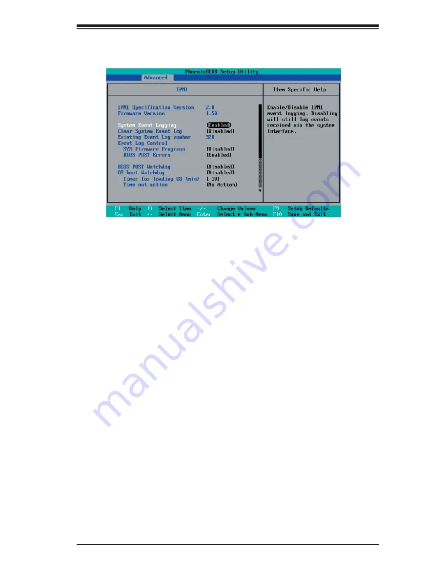
IPMI (The option is available only when an IPMI card is 

installed in the system.)

IPMI Specifi cation Version

: This item displays the current IPMI Version.

Firmware Version: 

This item displays the current Firmware Version.

System Event Logging

Select Enabled to enable IPMI Event Logging. When this function is set to Disabled, 

the system will continue to log events received via system interface. The options 

are 

Enabled 

and Disabled.

Clear System Event Logging

Enabling this function to force the BIOS to clear the system event logs during the 

next cold boot. The options are Enabled and 

Disabled

.

Existing Event Log Number

This item displays the number of the existing event log.

Event Log Control

System Firmware Progress

Enabling this function to log POST progress. The options are Enabled and 

Disabled

.

BIOS POST Errors

Enabling this function to log POST errors. The options are Enabled and 

Disabled

.

Summary of Contents for X7DWN+

Page 1: ...X7DWN USER S MANUAL Revision 1 0a SUPER...

Page 2: ...r the resolution of any such disputes Super Micro s total liability for all claims will not exceed the price paid for the hardware product FCC Statement This equipment has been tested and found to com...

Page 3: ...gh performance quad processor or dual processor DP workstation and enter prise server environments Please refer to our web site http www supermicro com products for updates on supported processors Thi...

Page 4: ...information given to ensure proper system installation or to prevent damage to the components Note Additional Information given to differentiate various models or to ensure cor rect system setup X7DWN...

Page 5: ...Preface Notes v...

Page 6: ...9 1 3 Special Features 1 10 1 4 PC Health Monitoring 1 10 1 5 ACPI Features 1 11 1 6 Power Supply 1 12 1 7 Super I O 1 12 Chapter 2 Installation 2 1 Static Sensitive Devices 2 1 Precautions 2 1 Unpack...

Page 7: ...Connector 2 21 Power SMB Connector 2 22 VGA Connector 2 22 Compact Flash Card PWR Connector 2 23 T SGPIO Headers 2 23 2 6 Jumper Settings 2 24 Explanation of Jumpers 2 24 GLAN Enable Disable 2 24 Clea...

Page 8: ...ocedures 3 2 3 3 Frequently Asked Questions 3 3 3 4 Returning Merchandise for Service 3 4 Chapter 4 BIOS 4 1 Introduction 4 1 4 2 Running Setup 4 2 4 3 Main BIOS Setup 4 2 4 4 Advanced Setup 4 6 4 5 S...

Page 9: ...in quality and performance Check that the following items have all been included with your motherboard If anything listed here is damaged or missing contact your retailer The following items are inclu...

Page 10: ...uper Micro Computer B V Het Sterrenbeeld 28 5215 ML s Hertogenbosch The Netherlands Tel 31 0 73 6400390 Fax 31 0 73 6416525 Email sales supermicro nl General Information support supermicro nl Technica...

Page 11: ...e The drawings and pictures shown in this manual were based on the latest PCB Revision available at the time of publishing of the manual The motherboard you ve received may or may not look exactly the...

Page 12: ...JOH1 LE1 FAN3 FAN8 CPUFAN2 JIDE1 JS2 JS3 JS4 JS5 JS6 J33 J7B3 J8B1 JPG1 J16 J29 J30 BT1 J22 J5 KB Mouse Fan5 Intel ESB 2 South Bridge 1 6 11 15 10 5 1 7 1 2 3 4 1 1 1 1 14 13 12 11 10 9 1 2 14 13 12 1...

Page 13: ...ctors JS1 JS6 JAR Alarm Buzzer Reset JD1 PWR LED pins1 3 SpeakerHeader pins 4 7 JF1 Front Control Panel Connector JL1 Chassis Intrusion Header JOH1 Overheat LED JP3 Power Fault Power Supply Failure PS...

Page 14: ...MHz slots Slot1 Slot2 One PCI U Universal slot Slot0 Gen 2 0 SIMSO Slot J16 BIOS 8 Mb Phoenix Flash ROM PCI 2 2 ACPI 1 0 Plug and Play PnP USB Keyboard support and SMBIOS 2 3 PC Health Monitoring Onbo...

Page 15: ...s One EIDE Ultra DMA 100 bus master interface One oppy port interface Two COM ports 1 header 1 port PS 2 mouse and PS 2 keyboard ports Up to ve USB 2 0 Universal Serial Bus 2 ports 3 Headers ES1000 32...

Page 16: ...XPx8 PCI EXPx8 PCI32 33MMZ ES1000 SATA 0 1 2 3 4 5 PCIEx8 PCIEx4 FWH LPC COM2 COM1 SIO W83627 FDD USB 0 1 2 3 4 SEPC IDE CONN ATA 100 KB MS PORT PORT PORT PORT PORTESI PORT PORT 0 7 8 1 2 3 4 4 1 2 0...

Page 17: ...128 MB for 4 FBD channels The PCI Express interfaces can be con gured to form x8 or x16 ports that can operate up to Gen 2 speeds in x16 con guration for enhanced graphics applications The Intel 631xE...

Page 18: ...onitor Fan Status Monitor with Firmware Control The PC health monitor can check the RPM status of the cooling fans The onboard CPU and chassis fans are controlled by Thermal Management via BIOS under...

Page 19: ...ation control ACPI leverages the Plug and Play BIOS data structures while providing a processor architecture indepen dent implementation that is compatible with both Windows 2000 and Windows 2003 Oper...

Page 20: ...to ensure adequate power supply to the system Also your power supply must supply 1 5A for the Ethernet ports Note The 12V 8 pin CPU Power Connector JPW3 is also required to support Intel 64 bit CPUs...

Page 21: ...vide legacy speed with baud rate of up to 115 2 Kbps as well as an advanced speed with baud rates of 250 K 500 K or 1 Mb s which support higher speed modems The Super I O supports one PC compatible pr...

Page 22: ...1 14 X7DWN User s Manual Notes...

Page 23: ...not touch its components peripheral chips memory modules or gold contacts When handling chips or modules avoid touching their pins Put the motherboard and peripherals back into their antistatic bags...

Page 24: ...stall the CPU heatsink 2 Intel s boxed Xeon CPU package contains the CPU fan and heatsink assembly If you buy a CPU separately make sure that you use only Intel certi ed multi directional heatsink and...

Page 25: ...ocket Do not move the CPU horizontally or vertically Do not rub the CPU against the surface or against any pins of the socket to avoid damaging the CPU or the socket 7 With the CPU inside the socket i...

Page 26: ...retention mechanism 3 Screw in two diagonal screws ie the 1 and the 2 screws until just snug do not fully tighten the screws to avoid possible damage to the CPU 4 Finish the installation by fully tig...

Page 27: ...utionary measures to avoid damaging these components when you install the motherboard to the chassis 1 Unscrew and remove the heatsink screws from the motherboard in the sequence as show in the pictur...

Page 28: ...odules see step 1 above Memory Support The X7DWN supports up to 128 GB fully buffered FBD ECC DDR 2 800 667 533 in 16 DIMMs Note 1 Due to OS limitations some operating systems may not show more than 4...

Page 29: ...emaining avail able for operational use will be reduced when 4 GB of RAM is used The reduc tion in memory availability is disproportional See the Memory Availability Table below Possible System Memory...

Page 30: ...low for the colors and locations of the various I O ports A Back Panel Connectors IO Ports Back Panel I O Port Locations and De nitions Back Panel Connectors 1 Keyboard Purple 2 PS 2 Mouse Green 3 Bac...

Page 31: ...are de signed speci cally for use with Supermicro server chassis See Figure 2 4 for the descriptions of the various control panel buttons and LED indicators Refer to the following section for descrip...

Page 32: ...JWOR JWOL Slot1 PCI X 100 133MHz USB 2 3 SMB I SATA0 LAN2 LAN Slot4 PCI E x4 JI2C1 JI2C2 BANK2 BANK3 BANK4 JL1 JK1 JAR 24 Pin PWR 4 Pin PWR 8 Pin PWR 3rd PWR Fail Detect CPU2 I SATA1 I SATA2 I SATA3 I...

Page 33: ...nitions JF1 Pin De nition 9 11 Vcc 10 12 Ground A B C A HDD LED B NIC1 LED C NIC2 LED JCF1 JP1 J7 FAN4 FAN2 FAN7 FAN1 JWF1 Buzzer FP Ctrl Panel PWRLED SPK JOH1 LE1 FAN3 FAN8 CPUFAN2 JPG1 KB Mouse Fan5...

Page 34: ...n Fail LED B PWR Supply Fail JCF1 JP1 J7 FAN4 FAN2 FAN7 FAN1 JWF1 Buzzer FP Ctrl Panel PWRLED SPK JOH1 LE1 FAN3 FAN8 CPUFAN2 JPG1 KB Mouse Fan5 Intel ESB 2 South Bridge 1 6 11 15 10 5 1 7 1 2 1 1 1 1...

Page 35: ...Reset Button Pin De nitions JF1 Pin De nition 3 Reset 4 Ground A Reset Button B PWR Button A B JCF1 JP1 J7 FAN4 FAN2 FAN7 FAN1 JWF1 Buzzer FP Ctrl Panel PWRLED SPK JOH1 LE1 FAN3 FAN8 CPUFAN2 JPG1 KB...

Page 36: ...A1 A2 Slot0 PCI U VGA CTRL SIMSO X7DWN 2 5 Connecting Cables ATX Power Connector There are a 24 pin main power sup ply connector JPW1 and an 8 pin CPU PWR connector JPW3 on the motherboard These powe...

Page 37: ...Fail Detect CPU2 I SATA1 I SATA2 I SATA3 I SATA4 I SATA5 Fan6 JPL1 CTRL B1 B2 A1 A2 Slot0 PCI U VGA CTRL SIMSO X7DWN Universal Serial Bus USB There are ve USB 2 0 Universal Serial Bus ports headers on...

Page 38: ...BANK3 BANK4 JL1 JK1 JAR 24 Pin PWR 4 Pin PWR 8 Pin PWR 3rd PWR Fail Detect CPU2 I SATA1 I SATA2 I SATA3 I SATA4 I SATA5 Fan6 JPL1 CTRL B1 B2 A1 A2 Slot0 PCI U VGA CTRL SIMSO X7DWN Fan Headers The X7D...

Page 39: ...MB I SATA0 LAN2 LAN Slot4 PCI E x4 JI2C1 JI2C2 BANK2 BANK3 BANK4 JL1 JK1 JAR 24 Pin PWR 4 Pin PWR 8 Pin PWR 3rd PWR Fail Detect CPU2 I SATA1 I SATA2 I SATA3 I SATA4 I SATA5 Fan6 JPL1 CTRL B1 B2 A1 A2...

Page 40: ...USB 2 3 SMB I SATA0 LAN2 LAN Slot4 PCI E x4 JI2C1 JI2C2 BANK2 BANK3 BANK4 JL1 JK1 JAR 24 Pin PWR 4 Pin PWR 8 Pin PWR 3rd PWR Fail Detect CPU2 I SATA1 I SATA2 I SATA3 I SATA4 I SATA5 Fan6 JPL1 CTRL B1...

Page 41: ...WOL Slot1 PCI X 100 133MHz USB 2 3 SMB I SATA0 LAN2 LAN Slot4 PCI E x4 JI2C1 JI2C2 BANK2 BANK3 BANK4 JL1 JK1 JAR 24 Pin PWR 4 Pin PWR 8 Pin PWR 3rd PWR Fail Detect CPU2 I SATA1 I SATA2 I SATA3 I SATA4...

Page 42: ...n PWR 8 Pin PWR 3rd PWR Fail Detect CPU2 I SATA1 I SATA2 I SATA3 I SATA4 I SATA5 Fan6 JPL1 CTRL B1 B2 A1 A2 Slot0 PCI U VGA CTRL SIMSO X7DWN Power Supply Failure Connect a cable from your power supply...

Page 43: ...133MHz USB 4 JWOR JWOL Slot1 PCI X 100 133MHz USB 2 3 SMB I SATA0 LAN2 LAN Slot4 PCI E x4 JI2C1 JI2C2 BANK2 BANK3 BANK4 JL1 JK1 JAR 24 Pin PWR 4 Pin PWR 8 Pin PWR 3rd PWR Fail Detect CPU2 I SATA1 I S...

Page 44: ...K1 Compact Flash IDE 1 Slot6 PCI E2 x8 SEPC CMOS Clear Slot5 PCI E2 x8 JWD Slot3 PCI E x8 Slot2 PCI X 100 133MHz USB 4 JWOR JWOL Slot1 PCI X 100 133MHz USB 2 3 SMB I SATA0 LAN2 LAN Slot4 PCI E x4 JI2C...

Page 45: ...8 Pin PWR 3rd PWR Fail Detect CPU2 I SATA1 I SATA2 I SATA3 I SATA4 I SATA5 Fan6 JPL1 CTRL B1 B2 A1 A2 Slot0 PCI U VGA CTRL SIMSO X7DWN A A Compact Flash PWR B SGPIO Header 1 C SGPIO Header 2 Compact F...

Page 46: ...C1 JI2C2 BANK2 BANK3 BANK4 JL1 JK1 JAR 24 Pin PWR 4 Pin PWR 8 Pin PWR 3rd PWR Fail Detect CPU2 I SATA1 I SATA2 I SATA3 I SATA4 I SATA5 Fan6 JPL1 CTRL B1 B2 A1 A2 Slot0 PCI U VGA CTRL SIMSO X7DWN 2 6 J...

Page 47: ...U2 I SATA1 I SATA2 I SATA3 I SATA4 I SATA5 Fan6 JPL1 CTRL B1 B2 A1 A2 Slot0 PCI U VGA CTRL SIMSO X7DWN CMOS Clear JBT1 is used to clear CMOS Instead of pins this jumper consists of contact pads to pre...

Page 48: ...2 PCI X 100 133MHz USB 4 JWOR JWOL Slot1 PCI X 100 133MHz USB 2 3 SMB I SATA0 LAN2 LAN Slot4 PCI E x4 JI2C1 JI2C2 BANK2 BANK3 BANK4 JL1 JK1 JAR 24 Pin PWR 4 Pin PWR 8 Pin PWR 3rd PWR Fail Detect CPU2...

Page 49: ...Pin PWR 4 Pin PWR 8 Pin PWR 3rd PWR Fail Detect CPU2 I SATA1 I SATA2 I SATA3 I SATA4 I SATA5 Fan6 JPL1 CTRL B1 B2 A1 A2 Slot0 PCI U VGA CTRL SIMSO X7DWN 3rd PWR Supply PWR Fault Detection J3P The syst...

Page 50: ...x8 JWD Slot3 PCI E x8 Slot2 PCI X 100 133MHz USB 4 JWOR JWOL Slot1 PCI X 100 133MHz USB 2 3 SMB I SATA0 LAN2 LAN Slot4 PCI E x4 JI2C1 JI2C2 BANK2 BANK3 BANK4 JL1 JK1 JAR 24 Pin PWR 4 Pin PWR 8 Pin PWR...

Page 51: ...n6 JPL1 CTRL B1 B2 A1 A2 Slot0 PCI U VGA CTRL SIMSO X7DWN GLAN LEDs There are two GLAN ports on the moth erboard Each Gigabit Ethernet LAN port has two LEDs The yellow LED indicates activity while the...

Page 52: ...1 CTRL B1 B2 A1 A2 Slot0 PCI U VGA CTRL SIMSO X7DWN Floppy Connector The oppy connector is located at J22 on the motherboard See the table on the right for pin de nitions Floppy Drive Connector Pin De...

Page 53: ...U FAN1 PSF SMBUS_PS 1 COM1 USB0 1 LAN1 VGA BANK1 Compact Flash IDE 1 Slot6 PCI E2 x8 SEPC CMOS Clear Slot5 PCI E2 x8 JWD Slot3 PCI E x8 Slot2 PCI X 100 133MHz USB 4 JWOR JWOL Slot1 PCI X 100 133MHz US...

Page 54: ...Compact Flash Card use only Do not use it for other devices If JIDE2 is populated with a Compact Flash Card JIDE1 the blue slot will be available for one device only For the Compact Flash Card to work...

Page 55: ...CPU making sure it is fully seated and connect the chassis speaker and the power LED to the motherboard Check all jumper settings as well 5 Use the correct type of CMOS onboard battery as recommended...

Page 56: ...same RAM speed for all DIMMs in the system 3 Make sure you are using the correct type of DDR2 FBD Fully Buffered ECC 800 667 533 SDRAM recommended by the manufacturer 4 Check for bad DIMM modules or s...

Page 57: ...r by fax at 408 503 8000 option 2 3 3 Frequently Asked Questions Question What are the various types of memory that my motherboard can support Answer The X7DWN has 16 240 pin DIMM slots that support D...

Page 58: ...before any warranty service will be rendered You can obtain service by calling your vendor for a Returned Merchandise Authorization RMA number When returning to the manufacturer the RMA number should...

Page 59: ...ed off a backup battery provides power to the CMOS Logic enabling it to retain system parameters When the computer is powered on the computer is con gured with the values stored in the CMOS Logic by t...

Page 60: ...pressing Delete immediately after turning the system on or 2 When the message shown below appears brie y at the bottom of the screen during the POST Power On Self Test press the Delete key to activate...

Page 61: ...s built Legacy Diskette A This setting allows the user to set the type of oppy disk drive installed as diskette A The options are Disabled 360Kb 5 25 in 1 2MB 5 25 in 720Kb 3 5 in 1 44 1 25MB 3 5 in a...

Page 62: ...ntrol This item determines whether the Phoenix BIOS will access the IDE Channel 0 Master Device via the LBA mode The options are Enabled and Disabled 32 Bit I O This option allows the user to enable o...

Page 63: ...is set to Enabled the item ICH RAID Code Base will be available for you to select either Intel or Adaptec Host RAID rmware to be activated If this item is set to Disabled the item SATA AHCI Enable wi...

Page 64: ...logo screen during boot up POST Errors Select Enable to stop the POST routine and allow the system to display error messages when an error occurs during bootup The options are Enabled and Disabled AC...

Page 65: ...es support for EFI OS booting The options are Enabled and Disabled OS Booting Set this feature to Enabled to allow the OS to boot up the system The options are Enabled and Disabled Power Loss Control...

Page 66: ...disable this function Select Write Through to allow data to be cached into the buffer and written into the system memory at the same time Select Write Protect to prevent data from being written into t...

Page 67: ...g a Linux graphic driver that requires the write combining con guration with 4GB or more memory The options are Enabled and Disabled PCI Con guration Access the submenu to make changes to the followin...

Page 68: ...Slot3 PCI Exp x8 Slot4 PCI Exp x4 Slot5 PCI Exp x8 and Slot6 PCI Exp x8 Access the submenu for each of the settings above to make changes to the following Option ROM Scan When enabled this setting wi...

Page 69: ...ed Intel VT for Direct I O VT d Select Enable to enable the functionality of the Intel Virtualization Technology for Direct I O VT d support by reporting the I O device assignment to VMM through the D...

Page 70: ...e function of memory sparing for Memory Bus Branch 0 or Branch 1 The options are Enabled and Disabled Branch 0 Rank Interleaving Branch 1 Rank Interleaving Select enable to enable Interleaved Memory f...

Page 71: ...ation Clocking Select Enabled to con gure FBD clock settings to support ITK testing The options are Disabled and Enabled Reserved Branch for ITK Test This feature allows the user to specify the memory...

Page 72: ...sor Options Access the submenu to make changes to the following settings CPU Speed This is a display that indicates the speed of the installed processor Frequency Ratio Available when supported by the...

Page 73: ...both cache lines for 128 bytes as comprised if Enabled The options are Disabled and Enabled Hardware Prefetch Available if supported by the CPU Set to this option to Enabled to enable the hardware com...

Page 74: ...le SMM When set to Enabled the SM Memory Region will become uncacheable effectively preventing viruses from modifying or corrupting critical system parameters The options are Enabled and Disabled Plea...

Page 75: ...rolled Base I O Address Select the base I O address for the parallel port The options are 378 278 and 3BC Interrupt This setting allows you to select the IRQ interrupt request for the parallel port Th...

Page 76: ...pacity It is not a setting View DMI Event Log Highlight this item and press Enter to view the contents of the event log Event Logging This setting allows you to Enable or Disable event logging ECC Eve...

Page 77: ...00 1200 2400 9600 19 2K 38 4K 57 6K and 115 2K Console Type This item allows you to set console redirection type The options are VT100 VT100 8bit PC ANSI 7bit PC ANSI VT100 VT UTF8 and ASCII Flow Cont...

Page 78: ...t 4 pin if your chassis uses 4 pin fans Select Disable to disable the fan speed control function and allow the onboard fans to constantly run at the full speed 12V The Options are 1 Running at the Ful...

Page 79: ...continue to log events received via system interface The options are Enabled and Disabled Clear System Event Logging Enabling this function to force the BIOS to clear the system event logs during the...

Page 80: ...efault setting is 10 minutes Please ignore this option when OS Boot Watch Dog is set to Disabled Time Out Option This feature allows the user to determine what action to take in an event of a system b...

Page 81: ...om motherboard sensors such as temperatures fan speeds and voltages of various components The following items will also appear IP Address IP Subnet Mask Default Gateway MAC Address Byte0 MAC Address B...

Page 82: ...password has been entered to the system Clear means such a password has not been used and Set means a user password has been entered Set Supervisor Password When the item Set Supervisor Password is h...

Page 83: ...he devices included in the candidate list above are currently disabled Use a key or a key to move the device up or down Use the f key or the r key to specify the type of an USB device either xed or re...

Page 84: ...Discarding Changes Highlight this item and hit Enter to exit the BIOS Setup utility without saving any changes you may have made Load Setup Defaults Highlight this item and hit Enter to load the defa...

Page 85: ...o two categories recoverable and terminal This section lists Beep Codes for recoverable POST errors Recoverable POST Error Beep Codes When a recoverable type of error occurs during POST BIOS will disp...

Page 86: ...A 2 X7DWN User s Manual Notes...

Page 87: ...driver displays When the Windows XP 2000 2003 Setup screen appears press S to specify additional device s Insert the driver diskette Intel AA RAID XP 2000 2003 Driver for ESB2 into Drive A and press t...

Page 88: ...s OS Setup screen will display From the Windows XP 2000 2003 Setup screen press the Enter key The XP 2000 2003 Setup will automatically load all device les and then continue with the Windows XP 2000 2...

Page 89: ...ystem before proceeding with the next item on the list The bottom icon with a CD on it allows you to view the entire contents of the CD Appendix C Installing Other Software Programs and Drivers C 1 In...

Page 90: ...displays crucial system information such as CPU temperature system voltages and fan status See the Figure below for a display of the Supero Doctor III interface Note 1 The default user name and passwo...

Page 91: ...Remote Control Note SD III Software Revision 1 0 can be downloaded from our Web site at ftp ftp supermicro com utility Supero_Doctor_III You can also download SDIII User s Guide at http www supermicr...

Page 92: ...C 4 X7DWN User s Manual Notes...

Page 93: ...expected to result in signi cant injury or loss of life or catastrophic property damage Accordingly Supermicro disclaims any and all liability and should buyer use or sell such products for use in su...

Reviews: